Table of Contents
Advertisement
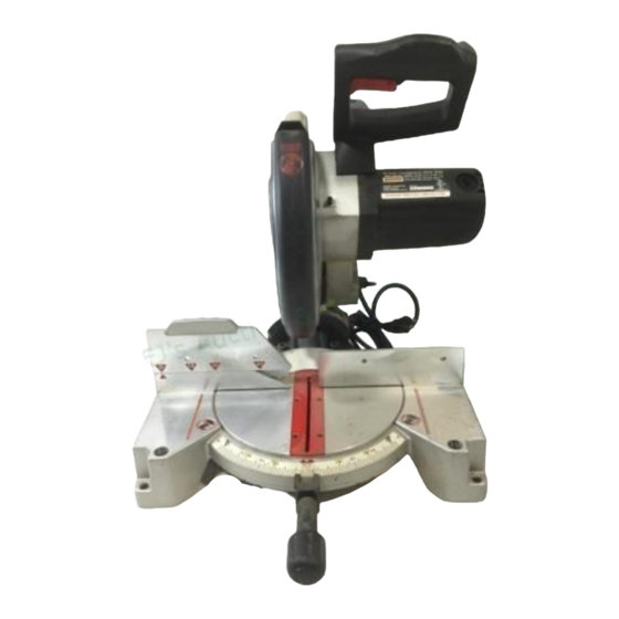
Operator's Manual
10 in. COMPOUND MITER SAW
Double Insulated
Model No.
315.243130
Save this manual
for
future reference
,A WARNING:
TO reduce the
risk of injury, the user must
read and understand
the
operator's
manual.
Customer
Help Line: 1-800-932-3188
Sears,
Roebuck
and Co.,
Hoffman
Estates,
IL 60179
USA
Visit the Craftsman
web page: www.sears.com/craftsman
983000-317
6-03
•Safety
• Features
•Adjustments
.Operation
.Maintenance
• Parts List
Advertisement
Table of Contents

Related Manuals for Craftsman 315.243130


Summary of Contents for Craftsman 315.243130
- Page 1 TO reduce the •Adjustments risk of injury, the user must read and understand .Operation operator's manual. .Maintenance • Parts List Customer Help Line: 1-800-932-3188 Sears, Roebuck and Co., Hoffman Estates, IL 60179 Visit the Craftsman web page: www.sears.com/craftsman 983000-317 6-03...
-
Page 2: Full One Year Warranty
• Table of Contents ..............................• Warranty and Introduction ........................• Rules For Safe Operation ..........................• Glossary ..............................• Product Specifications and Unpacking ................• Labels ........................• Loose Parts and Tools Needed ..............• Features ......................10-12 • Adjustments .............................. -
Page 3: Double Insulation
Thepurpose ofsafetysymbols isto attract y ourattention topossible dangers. Thesafety symbols, a ndthe explanations withthem,deserve yourcareful a ttention andunderstanding. Thesafetywarnings d o notby themselves e liminate anydanger. T heinstructions o rwarnings t heygivearenotsubstitutes f orproper accident prevention m easures. Symbol Meaning DANGER: Indicates an imminently hazardous situation which, if not avoided, will result in death or serious injury. - Page 4 • INSPECT TOOL CORDS AND EXTENSION and the type of cut. Do not use blades with incor- rect size holes. Never use blade washers or blade CORDS PERIODICALLY and, if damaged, have bolts that are defective or incorrect. The maximum repaired by a qualified service technician at a Sears store or repair center.
- Page 5 • MAKE SURE THE MITER TABLE AND SAW ARM • WHEN SERVICING, use only identical Craftsman (BEVEL FUNCTION) ARE LOCKED IN POSITION replacement parts. Use of any other parts may BEFORE OPERATING YOUR SAW. Lock the miter create a hazard or cause product damage.
- Page 6 • NEVER lift this tool by gripping the sliding miter ,_WARNING: Some dust created by power fence, sanding, sawing, grinding, drilling, and other • AVOID direct eye exposure when using the laser construction activities contains chemicals known guide, to cause cancer, birth defects or other reproduc- tive harm.
- Page 7 Blade Diameter 10 in. Cutting Capacity with Miter at 0°/Bevel 0°: Blade Arbor 5/8 in. 5-7/16 in. wide x 2-9/16 in. thick 3-1/2 in. thick x 4 in. wide No Load Speed 5000 RPM Maximum Cutting Capacity with Miter at 45°/Bevel 0°: Rating 120 Volts, 60 Hz-AC Only, 15 Amperes 3-7/8 in.
- Page 8 10 inch Compound Miter Saw DOUBLE INSULATED 5,000RPM 120VOLTS 60Hz ACONLY 15 A WHEN SERVICING, USEONLY ,DENT,CAL MODEL 315.243130 SER. NO. CRAFTSMAN REPLACEMENT PARTS. C_:S MADE IN TAIWAN SEARS, ROEBUCK AND CO, J STATIONARY TOOL • Customer Help Line 1-800-932-3188...
- Page 9 Thefollowing itemsareincluded withyourCompound M iterSaw: • Saw Blade - 10 in. • 6 mm Hex Key Wrench • Miter Lock Handle • 8 mm Hex Key Wrench • Dust Guide • Laser Guide • Blade Wrench • Hex Key Bolt •...
-
Page 10: Amp Motor
CUTTING CAPACITIES KNOW YOUR COMPOUND MITER See Figure 3. When the miter angle (miter table) is set at 0 ° and Before attempting to use your saw, familiarize yourself the bevel angle is set at 0°: with all operating features and safety requirements. Your saw will cut materials up to a maximum 5-7/16 in. - Page 11 CARRYING HANDLE SPINDLE LOCK BUTTON See Figure 4. See Figure 5. For convenience when carrying or transporting your A spindle lock button has been provided for locking miter saw from one place to another, a carrying the spindle which keeps the blade in your saw from handle has been provided on top of the saw arm as rotating.
- Page 12 POSITIVE STOPS ON MITER TABLE 173J16" 313/32" Positive stops have been provided at 0°, 22-1/2 ° and 313/32"_ 45 °. The 22-1/2 ° and 45 ° positive stops have been 3 29132" I provided on both the left and right side of the miter table.
- Page 13 TO INSTALL BLADE WARNING:Toprevent a ccidental starting that couldcausepossible serious personal injury, See Figures 10, 11, and 12. assemble all parts to yoursawbefore connecting itto power supply. S awshouldneverbe WARNING: A 10 in. blade is the maximum connected topower supply whenyouare blade capacity of your saw.
- Page 14 PHILLIPS LOWER • Wipe a drop of oil onto inner blade washer and SCREW_ BLADEGUARD outer blade washer where they contact the blade. ,& WARNING: If inner blade washer has been removed, replace it before placing blade on spindle. Failure to do so could cause an accident since blade will not tighten properly.
- Page 15 Note:Manyoftheillustrations i nthismanual s how MITERFENCE onlyportions ofyourcompound mitersaw.Thisis MITERTABLE intentional sothatwecanclearly showpointsbeing madeinthe illustrations. Never o perate yoursaw © © without a llguards securely in place andin good operating condition. SQUARING THE MITER TABLE TO THE FENCE See Figures 13 - 16. •...
- Page 16 • Retighten the screws securely and recheck the SQUARING THE SAW BLADE TO THE blade-to-fence alignment. FENCE See Figures 17- 20. MITER FENCE • Unplug your saw. WARNING: Failure to unplug your saw could result in accidental starting causing possible serious personal injury.
- Page 17 • If the top or bottom of the saw blade angles away SQUARING BLADE TO THE from the square as shown in figures 22 and 23, MITER TABLE adjustments are needed. See Figures 21 - 24. • Unplug your saw. MITER FENCE WARNING:...
-
Page 18: Pivot Adjustment
TRAVEL PIVOT ADJUSTMENT • The saw arm should rise completely to the up position by itself. If the saw arm does not raise by itself or if there is play in the pivot joints, have saw repaired by a qualified service technician at your nearest Sears store or repair center to avoid risk of personal injury. -
Page 19: Cutting With Your Compound Miter Saw
DEPTHSTOP WARNING: Before starting any cutting ADJUSTMENT operation, clamp or bolt your compound miter SCREW saw to a workbench. Never operate your miter saw on the floor or in a crouched position. Failure to heed this warning can result in serious personal injury. - Page 20 Slowly lower the blade into and through the workpiece. See Figure 26. Release the switch trigger and allow the saw STRAIGHT blade to stop rotating before raising the blade out CROSSCUT of workpiece. Wait until the electric brake stops blade from turning before removing the workpiece from the miter table.
-
Page 21: Bevel Cut
When cutting long pieces of lumber or molding, support the opposite end of the stock with a roller BEVELCUT stand or with a work surface level with the saw table. See Figure 31. Align the cutting line on the workpiece with the edge of saw blade. - Page 22 TO MAKE A COMPOUND CUT WITH YOUR • Recheck miter angle setting. Make a test cut in scrap material. MITER SAW Place the workpiece flat on the miter table with • Pull out the lock pin and lift saw arm to its full one edge securely against the fence.
- Page 23 Before turning onthesaw,perform a dryrunofthe cutting operation j ustto make surethatno problems w illoccurwhenthecutis made. Grasp thesawhandle firmlythensqueeze the switchtrigger. A llowseveral s econds forthe blade toreachmaximum speed. Slowly lowerthebladeintoandthrough thework- piece. See Figures 29 and 30. Release the switch trigger and allow the saw blade to stop rotating before raising the blade out of workpiece.
-
Page 24: Cutting Compound Miters
CUTTING COMPOUND MITERS To aid in making the correct settings, the compound angle setting chart below has been provided. Since com- pound cuts are the most difficult to accurately obtain, trial cuts should be made in scrap material, and much thought and planning made, prior to making your required cut. -
Page 25: Cutting Crown Molding
CUTTING CROWN MOLDING molding with its broad back surface flat on the miter table and against the fence. Your compound miter saw does an excellent job of When setting the bevel and miter angles for com- cutting crown molding. In general, compound miter pound miters, remember that the settings are interde- saws do a better job of cutting crown molding than pendent;... - Page 26 Bevel Angle Type of Cut Setting Left side, inside corner 1. Top edge of molding against fence 33.85 ° 2. Miter table set right 31.62 ° 3. Save left end of cut Right side, inside corner 1. Bottom edge of molding against fence 33"85°...
-
Page 27: Operation
MOUNTING LASER GUIDE OPERATION See Figure 36. See Figure 37. • Unplug your saw. The laser guide will generate a red colored line on the work surface when the saw blade is spinning above 500 rpm. The red laser line will appear as a broken WARNING: Failure to unplug your saw could line on the workpiece when the blade assembly is in... - Page 28 CHANGING BATTERIES See Figure 38. • Unplug your saw. LASERGUIDE SUPPORT WARNING: Failure to unplug your saw could result in accidental starting causing possible serious personal injury. Remove the laser guide from the saw. Lay laser guide on a flat surface with the two phillips screws facing upward.
-
Page 29: Extension Cords
Always wear safety goggles or WARNING: When servicing, use only identical Craftsman replacement parts. Use of any other safety glasses with side shields during power part may create a hazard or cause product tool operation or when blowing dust. If operation damage. - Page 30 CRAFTSMAN COMPOUND MITER SAW- MODEL NUMBER 315.243130 Figure A...
- Page 31 CRAFTSMAN COMPOUND MITER SAW- MODEL NUMBER 315.243130 a plate housing. Always correspondence regarding your The model number will be found attached to the motor mention the model number in all MITER SAW or when ordering repair parts. PARTS LIST FOR FIGURE A...
- Page 32 CRAFTSMAN COMPOUND MITER SAW- MODE5NUMBER 315.243130...
- Page 33 CRAFTSMAN COMPOUND MITER SAW- MODEL NUMBER 315.243130 The model will found attached the model number on a plate to the motor housing. Always mention number all correspondence regarding your MITER SAW or when ordering repair parts. PARTS LIST FOR FIGURE B...
- Page 35 CRAFTSMAN COMPOUND MITER SAW- MODEL NUMBER 315.243130 a plate The model number will be found attached to the motor housing. Always mention the model number in all correspondence regarding your MITER SAW or when ordering repair parts. PARTS LIST FOR FIGURE C...
- Page 37 CRAFTSMAN COMPOUND MITER SAW- MODEL NUMBER 315.243130 The model will found attached the model number on a plate to the motor housing. Always mention number all correspondence regarding your MITER SAW or when ordering repair parts. PARTS LIST FOR FIGURE D...
- Page 38 Get it fixed, at your home or ours! Your Home For repair-in your home-of all major brand appliances, lawn and garden equipment, or heating and cooling systems, no matter who made it, no matter who sold it! For the replacement parts, accessories owner's manuals that you need to do-it-yourself.