Table of Contents
Advertisement
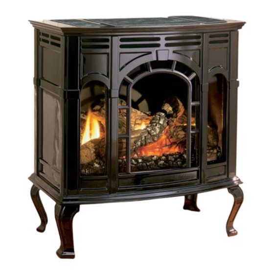
The Classic Cast Iron Stoves
This appliance may be installed in an aftermarket,
permanently located, manufactured (mobile) home,
where not prohibited by local codes.
This appliance is only for use with the type of gas
indicated on the rating plate. This appliance is not
convertible for use with other gases.
WARNING: If the information in these instruc-
tions are not followed exactly, a fire or explosion
may result causing property damage, personal
injury or loss of life.
— Do not store or use gasoline or other flamma-
ble vapors and liquids in the vicinity of this or
any other appliance.
— WHAT TO DO IF YOU SMELL GAS
•
Do not try to light any appliance.
•
Do not touch any electrical switch; do not
use any phone in your building.
•
Immediately call your gas supplier from a
neighbor's phone. Follow the gas suppli-
er's instructions.
•
If you cannot reach your gas supplier, call
the fire department.
— Installation and service must be performed by
a qualified installer, service agency or the gas
supplier.
16938-3-0806
INSTALLATION INSTRUCTIONS
OWNER'S MANUAL
AND
CAST IRON
UNVENTED ROOM HEATER
MODEL
CIVF-25-21
EFFECTIVE DATE
AUGUST 2006
Installer: Leave this manual with the appli-
ance.
Consumer: Retain this manual for future refer-
ence.
This is an unvented gas-fired heater. It uses air
(oxygen) from the room in which it is installed.
Provisions for adequate combustion and ventilation
air must be provided. Refer to page 6.
WARNING: If not installed, operated and main-
tained in accordance with the manufacturer's
instructions, this product could expose you to
substances in fuel or from fuel combustion which
can cause death or serious illness.
WATER VAPOR: A BY-PRODUCT OF UNVENT-
ED ROOM HEATERS
Water vapor is a by-product of gas combustion. An
unvented room heater produces approximately one
(1) ounce (30ml) of water for every 1,000 BTU's
(.3KW's) of gas input per hour. Refer to page 6.
Page 1
Advertisement
Table of Contents

Related Manuals for White Mountain Hearth CIVF-25-21

Summary of Contents for White Mountain Hearth CIVF-25-21
-
Page 1: Installation Instructions
Water vapor is a by-product of gas combustion. An unvented room heater produces approximately one (1) ounce (30ml) of water for every 1,000 BTU's (.3KW's) of gas input per hour. Refer to page 6. CAST IRON MODEL CIVF-25-21 EFFECTIVE DATE AUGUST 2006 ance. ence. Page 1... -
Page 2: Table Of Contents
Maintenance ...19 Troubleshooting ... 20-21 How To Order Repair Parts ...21 Parts List for Stove Casting ...22 Parts List for CIVF-25-21 ...22 Parts View for Stove Casting ...23 Parts View for CIVF-25-21 ...24 Optional Blower Installation Instructions ... 25-26 Service Notes ...27... -
Page 3: Important Safety Information
IMPORTANT SAFETY INFORMATION DO NOT OPERATE THIS APPLIANCE WITHOUT FRONT PANEL INSTALLED. • An unvented room heater having an input rating of more than 6,000 Btu per hour shall not be installed in a bathroom. • An unvented room heater having an input rating of more than 10,000 Btu per hour shall not be installed in a bedroom or bathroom. -
Page 4: Safety Information For Users Of Lp Gas
SAFETY INFORMATION FOR USERS OF LP-GAS Propane (LP-Gas) is a flammable gas which can cause fires and explosions. In its natural state, propane is odorless and colorless. You may not know all the following safety precau- tions which can protect both you and your family from an accident. -
Page 5: Introduction
Always consult your local Building Department regarding regulations, codes or ordinances which apply to the installation of an unvented room heater. This appliance may be installed in an aftermarket* permanently located, manufactured (mobile) home, where not prohibited by state or local codes. *Aftermarket: Completion of sale, not for purpose of resale, from the manufacturer. -
Page 6: Water Vapor: A By-Product Of Unvented Room Heaters
WATER VAPOR: A BY-PRODUCT OF UNVENTED ROOM HEATERS Water vapor is a by-product of gas combustion. An unvented room heater produces approximately one (1) ounce (30ml) of water for every 1,000 BTU's (.3KW's) of gas input per hour. Unvented room heaters must be used as supplemental heat (a room) rather than a primary heat source (an entire house). -
Page 7: Gas Supply
Check all local codes for requirements, especially for the size and type of gas supply line required. Recommended Gas Pipe Diameter Pipe Length Schedule 40 Pipe Inside Diameter Nat. L.P. 0-10 feet 1/2” 3/8” 0-3 meters 12.7mm 9.5mm 10-40 feet 1/2”... -
Page 8: Clearances
Clearances (Figures 2, 3 and 4) When facing the front of the appliance the following minimum clearances to combustible construction must be maintained. Top of appliance (ceiling) Rear Wall Side Wall Heater Corners (45° angle) to Wall Floor Provide adequate clearances around air openings. Adequate accessibility clearances for purposes of servicing and proper operation must be provided. -
Page 9: Appliance Hardware Package
APPLIANCE HARDWARE PACKAGE Figure 5 16938-3-0806 Appliance Hardware Package Parts List Part Description 1/4-20 x 1" Phillips Head Bolt 1/4-20 x 3/8" Phillips Head Bolt 1/4-20 x 1/2" Leveling Bolt No. 10 x 1/2" Hex Washer Head Screw 1/4-20 Washer Head Nut Leg Pad "A"... -
Page 10: Assembly Of Stove Casting
ASSEMBLY OF STOVE CASTING Assembly of Stove Casting (Figures 6, 7, 8, 9, 10, 11 and 12) Attention: Included in the hardware package are (8) 1/4" inside diameter washers. A 1/4" washer may be used with a 1/4-20 x 3/8" bolt when assembling the stove casting parts. - Page 11 7. Refer to Figure 7, the rear cover has (4) keyholes for attachment to the casting sides. Stand the casting sides on the floor with the (2) bolts attached half-way into the edges of the rear cover positioned at the rear. The large diameter holes in the keyholes of the rear cover will be toward the floor.
-
Page 12: Assembly Of Stove Casting
ASSEMBLY OF STOVE CASTING (continued) 11. Refer to Figure 9, attach casting front to casting by using the (4) retaining tabs on the casting front. The (2) top, retaining tabs on the casting front will be placed behind the (2) top, locator tabs on the front of the casting sides. -
Page 13: Optional Stone Inlay Installation
OPTIONAL STONE INLAY INSTALLATION Whenever the standard grill top is replaced with a stone inlay you must install the top shield and heat shield, which are provided with the stone inlay. Installation of Optional Stone Inlay 1. Remove left grill, center grill and right grill from casting top. 2. -
Page 14: Log Placement
1. Remove screen front from inner body by removing (2) 10 x 1/2" screws. 2. Remove logs from interior of firebox. Remove all protective packaging from logs and interior of firebox. 3. Place front log onto two (2) front pins on inner bottom. 4. -
Page 15: Lighting Instructions
FOR YOUR SAFETY READ BEFORE LIGHTING WARNING: IF YOU DO NOT FOLLOW THESE INSTRUCTIONS EXACTLY, A FIRE OR EXPLOSION MAY RESULT CAUSING PROPERTY DAMAGE, PERSONAL INJURY OR LOSS OF LIFE. A. This appliance has a pilot which must be lighted by hand. When lighting the pilot, follow these instructions exactly. -
Page 16: Pilot Flame Characteristics
PILOT FLAME CHARACTERISTICS Figure 15 shows a correct pilot flame pattern. The correct flame will be blue and will extend beyond the thermocouple and ther- mopile. The flame will surround the thermocouple and thermopile just below the tip. A slight yellow flame may occur where the pilot flame and main burner flame meet. -
Page 17: Main Burner Flame Characteristics
MAIN BURNER FLAME CHARACTERISTICS Figure 18 shows a correct main burner flame pattern. Figure 19 shows an incorrect main burner flame pattern. If main burner flame pattern is incorrect, as shown in Figure 19 • See Troubleshooting, pages 20-21. Correct Main Burner Flame Figure 18 Incorrect Main Burner Flame Figure 19... -
Page 18: Wiring
CIVF-25 ON/OFF/REMOTE Switch CIVF-25 is equipped with an ON/OFF/REMOTE switch which is located on the wire channel. A wire harness is attached to the ON/OFF/REMOTE switch. The red, black and green (wires) female push-ons attach to the ON/OFF/REMOTE switch. At the opposite end of the wire harness, the black and green (wires) female push- ons attach to the gas valve. -
Page 19: Maintenance
Wiring Diagram (Figure 21) Figure 21 IMPORTANT: Turn off gas before servicing appliance. It is recommended that a qualified service technician perform these check-ups at the beginning of each heating season. • Clean Burner and Control Compartment Keep the control compartment, logs and burner area surrounding the logs clean by vacuuming or brushing at least twice a year. -
Page 20: Troubleshooting
SYMPTOMS - POSSIBLE CAUSES AND CORRECTIONS IMPORTANT: Operating heater where impurities in air exist may create odors. Cleaning supplies, paint, paint remover, cigarette smoke, cements and glues, new carpet or textiles, etc., create fumes. These fumes may mix with combustion air and create odors. 1. -
Page 21: How To Order Repair Parts
Do not order bolts, screws, washers or nuts. They are standard hardware items and can be purchased at any local hardware store. Shipments contingent upon strikes, fires and all causes beyond our control. Empire Comfort Systems, Inc. Nine Eighteen Freeburg Ave. Belleville, Illinois 62222-0529 16938-3-0806 12. -
Page 22: Parts List For Stove Casting
USE ONLY MANUFACTURER'S REPLACEMENT PARTS. USE OF ANY OTHER PARTS COULD CAUSE INJURY OR DEATH. Page 22 Index * PART IS NOT SUPPLIED WITH CASTING, IT IS INCLUDED IN THE FIREBOX HARDWARE PACKAGE PARTS LIST FOR CIVF-25-21 Index Part Number Description... -
Page 23: Parts View For Stove Casting
PARTS VIEW FOR STOVE CASTING Models: CIFB-1, CIPB-1, CIPG-1, CIPS-1, CIPN-1, CIPR-1 16938-3-0806 Page 23... -
Page 24: Parts View For Civf-25-21
PARTS VIEW FOR CIVF-25-21 Page 24 16938-3-0806... -
Page 25: Optional Blower Installation Instructions
OPTIONAL BLOWER INSTALLATION INSTRUCTIONS Installing Optional CIB-2 Blower 1. Loosen, but do not remove, (4) hex-head screws located on the exterior, bottom of the appliance. 2. Position the blower assembly at the rear of the appliance. The blower assembly has (4) keyholes for attachment to the exterior, bottom of the appliance. -
Page 26: Optional Blower Installation Instructions
OPTIONAL BLOWER INSTALLATION INSTRUCTIONS (continued) Cleaning The blower wheel will collect lint and could require cleaning once a year. If the air output decreases or the noise level increases, it indicates a dirty wheel. Blower Motor The blower motor does not have oiling holes. Do not attempt to oil blower motor. -
Page 27: Service Notes
SERVICE NOTES 16938-3-0806 Page 27... - Page 28 Empire Comfort Systems, Inc. 918 Freeburg Ave. Belleville, IL 62220 PH: 618-233-7420 or 800-851-3153 FAX: 618-233-7097 or 800-443-8648 info@empirecomfort.com www.empirecomfort.com Page 28 16938-3-0806...