Table of Contents
Advertisement
Advertisement
Table of Contents

Summary of Contents for EarthStone BV400C-2
-
Page 1: Installation And Operation
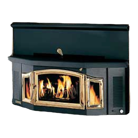
INSTALLATION AND OPERATION MANUAL EPA CERTIFIED CATALYTIC WOOD BURNING FIREPLACE INSERT RETAIN THESE MODEL BV400C-2 INSTRUCTIONS FOR FUTURE REFERENCE THIS APPLIANCE MUST BE INSTALLED BY A QUALIFIED INSTALLER. READ ENTIRE MANUAL THOROUGHLY BEFORE INSTALLATION. P/N 775,005M Rev. M, 12/03 PAGE 1... -
Page 2: Important Warnings
IMPORTANT WARNINGS CAUTION: PLEASE READ THIS ENTIRE MANUAL BEFORE YOU INSTALL AND USE YOUR NEW ROOM HEATER. FOR YOUR SAFETY, FOLLOW THE INSTALLATION, OPERATION AND MAINTENANCE INSTRUC- TIONS EXACTLY, WITHOUT DEVIATION. FAILURE TO FOLLOW THESE INSTRUCTIONS MAY RESULT IN PROPERTY DAMAGE, BODILY INJURY, OR EVEN DEATH. IF THIS APPLIANCE IS NOT PROPERLY INSTALLED, A HOUSE FIRE MAY RESULT. -
Page 3: Table Of Contents
TABLE OF CONTENTS CONGRATULATIONS ON THE PURCHASE OF Important Warnings ..........2 YOUR NEW WOOD BURNING FIREPLACE INSERT MANUFACTURED BY LENNOX HEARTH PROD- Testing/Listing, EPA, Using this Manual....3 UCTS. Planning Your Installation ........4-6 When you purchased your new insert, you joined the ranks of thousands of concerned individuals Installation ............ -
Page 4: Planning Your Installation
PLANNING YOUR INSTALLATION QUESTIONS TO ASK LOCAL BUILDING OFFICIAL FLOOR PROTECTION A correct installation is critical and imperative for reduc- This appliance requires a heat resistant non-combustible ing fire hazards and perilous conditions that can arise approved fireplace hearth or hearth extension. If a hearth when wood burning appliances are improperly installed. - Page 5 PLANNING YOUR INSTALLATION CLEARANCES Raised Firebox WARNING: IT IS VERY IMPORTANT THAT YOU OB- SERVE THE MINIMUM CLEARANCES. DO NOT STORE FIREWOOD WITHIN THIS CLEARANCE SPACE. FAILURE TO MAINTAIN CLEARANCES TO ALL COMBUSTIBLES MAY RESULT IN A HOUSE FIRE. There are listed clearances for your fireplace insert DRAFT REQUIREMENTS which were determined in a Laboratory testing and must The appliance is merely one component of a larger sys-...
- Page 6 PLANNING YOUR INSTALLATION FACTORY BUILT FIREPLACES Venting Requirements for masonry fireplace: This appliance is approved for installation into a listed The fireplace damper must be secured in the open po- factory built solid fuel burning fireplace. The fireplace sition. As a minimum, a flue extension past the fireplace firebox must accept the insert without modification other header is required.
-
Page 7: Installation
INSTALLATION FIREPLACE INSTALLATION CATALYTIC TEMPERATURE PROBE Install temperature probe prior to installing insert. CHIMNEY To install the Catalytic Temperature Probe locate the plug on the TERMINATION CAP top, right-hand side of the bypass control rod. Remove the plug, install the sleeve, and place probe in sleeve. It may be necessary to bend the flange on the plug so it won't interfere with the probe temperature indicator. - Page 8 INSTALLATION INSTALLATION STEPS 11. The floor of the fireplace is lower then the hearth, 1. Remove all ashes from the fireplace. turn the adjusting bolt (located at the bottom of the 2. Remove all materials inside the insert and set them groove in the rear of the insert firebox) clockwise aside.
- Page 9 INSTALLATION Heat Deflector Must Be Installed If There is a Mantel Mantel Heat Deflector 16. Push the insert back until surround panel insulation is compressed against the fireplace front, forming a 14. Push the insert to its desired position in the fire- tight seal.
- Page 10 INSTALLATION POSITIVE FLUE CONNECTION FOR MASONRY FIRE- A preferable installation is the positive flue connection (a posi- PLACE tive seal between the flue extension and the chimney). This can be achieved by using a filler plate. A filler plate can be A Professional should inspect chimney prior to installation to made by making a cardboard pattern to fit the fireplace throat.
-
Page 11: Product Features And Controls
PROCUCT FEATURES AND CONTROLS BLOWER SYSTEM AIR AND DAMPER CONTROLS The 500-CFM room air circulation blower system comes equipped with a variable speed control (rheostat). The blower system can be operated manually or set to oper- ate automatically (so the blowers will turn on when the insert is hot and turn off when the insert is cool). -
Page 12: Care And Operation
CARE AND OPERATION This unit is designed to provide a flow of air over the in- FUEL DOOR side of the glass, where along with high heat helps keep CAUTION: When opening the door, do not extend it it clean. When operating the fireplace insert on low for beyond its normal travel. - Page 13 CARE AND OPERATION BREAK-IN PERIOD Your fireplace insert finish is a high temperature paint When refueling a hot stove with the catalyst still operating, that requires time and temperature to completely cure. no refiring step is necessary. Just open the bypass, set the We recommend that you ventilate the house during the primary air control to high, open the door approximately initial burns.
- Page 14 CARE AND OPERATION BLOWER SYSTEM The Blower System consists of a ON/OFF rocker switch, WARNING: This appliance is equipped with a blower a variable speed blower speed control switch (rheostat), system which has a flexible electrical power cord a thermally activated switch (fan disc) and 4 axial blow- with a three-prong (grounding) plug for your protec- ers.
-
Page 15: Recommended Fuel
MAINTENANCE BURN RECOMMENDED FUEL Wood that is kept outdoors, either covered with a tarp, or This appliance is approved for use with natural dry wood not covered at all, will not burn well until it has been in an only. Burning materials other than natural wood will shorten enclose space for one to two months. - Page 16 MAINTENANCE DOOR / GLASS GASKET AND ASH DUMP GASKET fore installations using this type of flue are more suscep- A 3/4" spun fiberglass gasket provides the seal around tible to creosote deposits. the fuel door and a flat spun fiberglass rope gasket (1/8” To inhibit the build up of creosote, adjust the primary air x 1”) provides the seal around the glass.
- Page 17 MAINTENANCE CLEANING BLOWERS REMOVING COMBUSTOR CLIP The blowers require inspection and cleaning annually to remove lint, dust, etc. If there are pets in the dwelling, the blowers should be cleaned at least twice a year To access, remove blower covers (remove the two ¼” hex head screws on each panel), then inspect propellers (replace if cracked or broken) and vacuum out lint, dust, and debris.
-
Page 18: Troubleshooting
TROUBLESHOOTING * SMOKES OUT FUEL DOOR WHEN OPEN * DOES NOT MAINTAIN A FIRE 1. The primary air control is closed. 1. Soft wood does not burn as long or as well as seasoned 2. The chimney is too cool. Set the primary air con- hardwood resulting in a short burn time. - Page 19 TROUBLESHOOTING OVERFIRING Overfiring Caused From Improper Operation If any part of the appliance glows, it is overfiring. Never burn the appliance with the fuel door open or Other symptoms may include: Cracking, warping or ajar, the ash dump cover off or the ash drawer open (if burning out of components, catalytic combustor may optional ash drawer is installed).
-
Page 20: Specifications
SPECIFICATIONS - Model BV400C-2 Maximum log length 24" Flue size 8" Width w/standard surround 48" Width at fireplace opening 29 1/2" Width at rear of firebox 21 1/2" Depth into Fireplace 15 3/4" Depth (overall) 26 1/4" Height * 20" Height w/standard surround 32"... -
Page 21: Replacement Parts List
COMPONENT DIAGRAMS – Model BV400C-2 ITEM NO DESCRIPTION Door and Glass Parts 27M67 Clip Set, Glass H0537 Door Assembly, Gold (handle included) 86-128 Gasket Kit, 3/4" Door Rope (includes adhesive) 27M81 Gasket Kit, Door Glass (10' of 10580) G400-7 Glass, Large Arched 11 x 17" (gasket not included) G410 Glass, Side 4 x 8 3/4"... - Page 22 COMPONENT DIAGRAMS – Model BV400C-2 Firebox Parts 11711 Cover, Ash Dump (w/ Gasket 4 1/4 x 8 3/8" x 1/2") 26M70 Damper Kit, Bypass (damper, linkage and rod) LB-102215 Damper Stop (sleeve for damper rod to limit travel of damper door) Firebrick, 3 ¼...
- Page 23 COMPONENT DIAGRAMS – Model BV400C-2 REPLACEMENT DAMPER KIT (Cat. No. 26M70) DRAFT MODULE ASSEMBLY (Cat. No. 26M68) Damper Stop Damper Rod LB-102215 Screws WIRE HARNESS KIT (P/N LB-102280) Damper Door Includes the following 3 Components: Wire Harness – Right Side Damper Blade Assembly DOOR ASSEMBLY - Cat.
-
Page 24: Optional Accessories
OPTIONAL ACCESSORIES - Model BV400C-2 Accessories * OFFSET ADAPTERS Part/ Model Description CAT NO. 14M77 (8" to 8" for Masonry Fireplaces) & Cat. No. 14M79 (8" to 6" for Factory Built Fireplaces) Installations 14M69 AD-BV400C Ash Drawer – Includes taller sur- requiring offsets can be handled using an offset adapter (it round side trim-35 ½”... -
Page 25: Safety/Listing Label
SAFETY / LISTING LABEL PAGE 25... -
Page 26: Epa Label
EPA LABEL PAGE 26... -
Page 27: Service / Maintenance Log
OWNERSHIP RECORDS Dealer’s Name: Dealer’s Address: City: State: Zip Code: Serial Number: Date of Purchase: Date Installed: Notes: SERVICE AND MAINTENANCE LOG Service Service Service Date Technician Description PAGE 27... - Page 28 1110 West Taft Avenue Orange, CA 92865...