
Related Manuals for Delta Electronics RTU-EN01

Summary of Contents for Delta Electronics RTU-EN01
-
Page 1: Operation Manual
RTU-EN01 Modbus TCP Remote I/O Communication Module Operation Manual DVP-0213920-01... -
Page 3: Table Of Contents
Modbus TCP Remote I/O Communication Module RTU-EN01 Introduction This operation manual only provides introductory information on electrical specification, installation and wiring. RTU-EN01 is an OPEN-TYPE device and therefore should be installed in an enclosure free of airborne dust, humidity, electric shock and vibration. The enclosure should prevent non-maintenance staff from operating the device (e.g. key or specific tools are required to open the enclosure) in case danger and damage on the device may occur. - Page 4 Modbus TCP Remote I/O Communication Module RTU-EN01 SETTING UP SOFTWARE....................16 Setting up Communications & Searching for Communication Modules in DCISoft ....16 Recording IP Address ....................... 18 Basic Settings........................... 19 Network Settings ........................21 Setting up Time Server ......................22 IP Filter .............................
-
Page 5: Introduction
Modbus TCP Remote I/O Communication Module RTU-EN01 Introduction To ensure correct installation and operation of RTU-EN01, please read this manual carefully before using your RTU-EN01. RTU-EN01is an Ethernet remote I/O module for remote setting through Delta’s DCISoft. RTU-EN01 supports maximum 256 digital input/output points. RTU-EN01 supports Modbus TCP protocol and can be used for remote monitoring with graphic control software or human machine interface. -
Page 6: Product Profile & Outline
Modbus TCP Remote I/O Communication Module RTU-EN01 Environment ESD (IEC 61131-2, IEC 61000-4-2): 8KV Air Discharge EFT (IEC 61131-2, IEC 61000-4-4): Power Line:±2KV, Digital Input: ±2KV, Communication I/O: ±2KV RS (IEC 61131-2, IEC 61000-4-3): 80MHz ~ 100MHz, 10V/m. 1.4GHz ~ 2.0GHz, Noise immunity 10V/m Conducted Susceptibility Test (EN61000-4-6, IEC61131-2 9.10): 150kHz ~ 80MHz,... -
Page 7: Product Profile
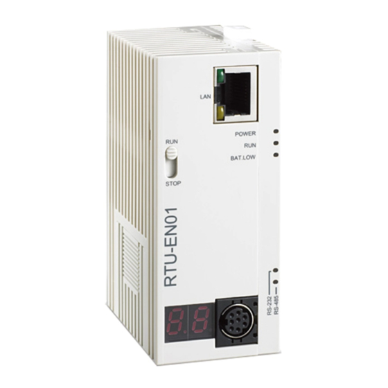
Modbus TCP Remote I/O Communication Module RTU-EN01 2.2 Product Profile 1. POWER indicator 12. RS-485 communication port 2. RUN indicator 13. Extension module positioning hole 3. BAT.LOW indicator 14. Nameplate 4. RUN/STOP switch 15. Extension port 5. RS-232 indicator 16. DIN rail (35mm) 6. -
Page 8: Run/Stop Switch
Modbus TCP Remote I/O Communication Module RTU-EN01 2.4 RUN/STOP Switch Status Explanation 1. RUN indicator on RTU-EN01 is ON. 2. Analog input/output module is in RUN status. 3. Smart PLC function is running. 1. Analog input/output module switches from RUN to STOP status. STOP 2. -
Page 9: Installing Rtu-En01 And Dvp Slim Series Digital Input/Output Module Onto Din Rail
Modbus TCP Remote I/O Communication Module RTU-EN01 LA N P O W E R R U N R U N B AT. LO W S TO P 3.2 Installing RTU-EN01 and DVP Slim Series Digital Input/Output Module onto DIN Rail Use standard 35mm DIN rail. -
Page 10: Word Devices & Bit Devices In Rtu-En01
Modbus TCP Remote I/O Communication Module RTU-EN01 DVPEN01-SL DVP28SV DVP28SV STOP Ethernet COM2 RTU-EN01 DI/DO AI/AO Word Devices & Bit Devices in RTU-EN01 4.1 Basic Registers (BR) Attribute Content Explanation Default Latched Set up by the system; read only. The model code of Model name H’0600 RTU-EN01= H’0600. -
Page 11: Explanations On Br
Modbus TCP Remote I/O Communication Module RTU-EN01 Attribute Content Explanation Default Latched ID of the 1st analog ID of the 1st analog I/O module I/O module ID of the 2nd analog ID of the 2nd analog I/O module I/O module ID of the 3rd analog ID of the 3rd analog I/O module I/O module... - Page 12 Modbus TCP Remote I/O Communication Module RTU-EN01 B R # 5: C OM 2 C o m mu n ic at io n S et t i ng s Explanations: b0 ~ b3 Interface Explanation Baud rate Baud rate Baud rate Data Data Data...
- Page 13 Modbus TCP Remote I/O Communication Module RTU-EN01 Code Indication How to correct Returning to default setting RTU-EN01 being powered Power supply in low voltage Check if the power supply of the module works normally. 1. Check if the settings of smart PLC are incorrect. 2.
-
Page 14: External Input Contacts (Rx)
Modbus TCP Remote I/O Communication Module RTU-EN01 BR#50 ~ BR#57: R TC Sett ings Explanations: For setting up the real-time clock (RTC). When BR#9 = 1, RTU-EN01 will stop to update the RTC values to BR#10 ~ #16. Once the setup is completed, RTU-EN01 will set BR#9 to 0. Allowed range for RTC: 1970/01/01 00:00:00 ~ 2037/12/31 23:59:59 BR#9 No action... -
Page 15: Word Devices & Bit Devices For Timers (T)
Modbus TCP Remote I/O Communication Module RTU-EN01 RCR# Attribute Content Explanation Default Latched The 5 analog I/O Control register for the 5 analog I/O 200 ~ 249 module module The 6 analog I/O Control register for the 6 analog I/O 250 ~ 299 module module... -
Page 16: Word Devices & Bit Devices For Counters (C)
Modbus TCP Remote I/O Communication Module RTU-EN01 T #1 ~ # 15: Tim er 1 ~ 1 5 Explanations: Please refer to T#0. 4.7 Word Devices & Bit Devices for Counters (C) Attribute Register/coil name Explanation Default Latched Counter 0 Counting up/down counter 0/OFF Counter 1... -
Page 17: Modbus Communication
Modbus TCP Remote I/O Communication Module RTU-EN01 Attribute Content Explanation Default Latched RTC 6 Real-time clock RTC 7 Real-time clock RTC 8 Real-time clock RTC 9 Real-time clock RTC 10 Real-time clock RTC 11 Real-time clock RTC 12 Real-time clock RTC 13 Real-time clock RTC 14... -
Page 18: Device Type & Device Address
Modbus TCP Remote I/O Communication Module RTU-EN01 5.3 Device Type & Device Address Discrete input Device type Modbus address (Hex) 6-digit Modbus address (Dec) Number 0x0400 ~ 0x04FF 101025 ~ 101280 Coil 0x0500 ~ 0x05FF 001281 ~ 001537 0x1600 ~ 0x160F 005633 ~ 005649 0x1900 ~ 0x190F 006401 ~ 006416... - Page 19 Modbus TCP Remote I/O Communication Module RTU-EN01 You will see the communication module found. DVP-PLC Operation Manual...
-
Page 20: Recording Ip Address
Modbus TCP Remote I/O Communication Module RTU-EN01 Double-click on the module to be set up to enter the setup page. The first page overviews the basic status of the module and information on the right-side module. The next page is for basic network setup. Consult your Internet Service Provider for relevant network setting. For other settings, see BR#11 ~ BR#13. -
Page 21: Basic Settings
Modbus TCP Remote I/O Communication Module RTU-EN01 IP list: In the list, you will see the network IPs already used. Click “Add” to record the known IP address into the list and next search for the module on the network by designated IP. Click the icon to search for the module. - Page 22 Modbus TCP Remote I/O Communication Module RTU-EN01 Module name: There can be many RTU-EN01 modules on the network. Thus, you can set up a module name for each module to identify the module when you need to use them. Network setup: Enable dynamic IP (DHCP) or static IP.
-
Page 23: Network Settings
Modbus TCP Remote I/O Communication Module RTU-EN01 the communication. The IP of the gateway has to be in the same subnet as RTU-EN01. The default gateway of RTU-EN01 is 192.168.1.1. Timer setting: For setting up TCP connection idle time, Modbus time-out and minimum delay time for every communication data. -
Page 24: Setting Up Time Server
Modbus TCP Remote I/O Communication Module RTU-EN01 Enter “192.168.0.2” into IP address. Click “OK” to complete the IP address setting of the PC. 6.5 Setting up Time Server RTU-EN01 offers real-time clock (RTC) functions. You can set up your own time for RTU-EN01 or update the time through NTP server. -
Page 25: Ip Filter
Modbus TCP Remote I/O Communication Module RTU-EN01 Enable time server: RTU-EN01 execute automatic time correction from the NTP server on the network every 6 hours to ensure the time is correct in the RTC. To enable this function, you have to set up first the IP address of the NTP server and the time zone and daylight saving time which your RTU-EN01 is in. -
Page 26: Smart Plc Setting: If-Then
Modbus TCP Remote I/O Communication Module RTU-EN01 Check the box to enable IP filter. Begin IP address: Start IP addresses allowed to establish connection. Max. 8 IPs are allowed. End IP address: End IP addresses allowed to establish connection. Max. 8 IPs are allowed. 6.7 Smart PLC Setting: IF-THEN RTU-EN01 has the independent Smart PLC function. -
Page 27: Smart Plc Setting: Timer
Modbus TCP Remote I/O Communication Module RTU-EN01 You can move the IF-THEN setting upwards or downwards to change the execution order of them. 6.8 Smart PLC Setting: Timer RTU-EN01 has the independent Smart PLC function. The timer is able to time following the system time. There are 16 timers in RTU-EN01. -
Page 28: Smart Plc Setting – Rtc
Modbus TCP Remote I/O Communication Module RTU-EN01 Enable: Decide whether to enable the counter in this column. Count up/count down: Decide whether the counter will be counting up or counting down. Up bound/low bound: The upper bound and lower bound of the counting. Range: -32,768 ~ 32,767. Count source RX NO.: No. -
Page 29: Analog Input/Output Modules
Modbus TCP Remote I/O Communication Module RTU-EN01 Enable: Decide whether to trigger the RTC in this column. Cyclic: Decide to trigger the RTC only once, or trigger it on a daily, weekly or monthly basis. Output auto-reset: After the RTC is triggered, decide whether to retain the output for a period of time and reset the RTC automatically. - Page 30 Modbus TCP Remote I/O Communication Module RTU-EN01 1. Corresponding table: Open DCISoft and it will automatically load in the control register information on the analog I/O modules. (When using Web settings, you have to load in the EDS file for analog I/O module by yourself.) Check the CR you are to read or write to establish a mapping table.
-
Page 31: I/O Monitoring Table
Modbus TCP Remote I/O Communication Module RTU-EN01 6.12 I/O Monitoring Table RTU-EN01 is able to monitor internal registers on-line. Scroll the table to monitor bit devices RX, RY, T, C, R, RCR and BR and the bit status and present value in the register. You can choose to monitor decimal or hex present value. -
Page 32: Setting Up Gateway
Modbus TCP Remote I/O Communication Module RTU-EN01 T#0 ~ T#15, total 16 bits and 16 registers. C#0 ~ C#15, total 16 bits and 16 registers. R#0 ~ R#15, total 16 bits and 16 registers. RCR#0 ~ RCR#399, total 400 registers. BR#0 ~ BR#63, total 64 registers. - Page 33 Modbus TCP Remote I/O Communication Module RTU-EN01 Parity Data length Stop bits Station address: The Modbus address. 2. Bit device For setting up the addresses for the bit type serial slave device and reading or the content in the designated slave. Station address: Enter the address of slave to be monitored.
- Page 34 Modbus TCP Remote I/O Communication Module RTU-EN01 3. Word device For setting up the addresses for the word type serial slave device and reading or the content in the designated slave. Station address: Enter the address of slave to be monitored. (Max. 16 slaves) MODBUS (Hex): Enter the 4-digit hex Modbus address of the slave to be monitored.
-
Page 35: Virtual Com
Modbus TCP Remote I/O Communication Module RTU-EN01 6.14 Virtual COM The virtual COM converts the data sent to RS-232 port into Ethernet. Select Virtual COM for COM2 mode (RS-485). The default setting for listen port is 20001. Open the setup page for Virtual COM. DVP-PLC Operation Manual... - Page 36 Modbus TCP Remote I/O Communication Module RTU-EN01 Press “Search”, and you will see all the connected devices on the network Select the device and click “OK”. Information on the device will be loaded in automatically. Press “OK” to complete the setup. Once the setup is completed, you will then be able to see the virtual COM just set in “Computer Management”.
-
Page 37: Security Setting
Modbus TCP Remote I/O Communication Module RTU-EN01 6.15 Security Setting To prevent the set values in RTU-EN01 from being modified, you can set up passwords to lock the settings in RTU-EN01. Setting up password Login: Log in to check and modify parameters. Password setup: Check the “Modify”... -
Page 38: Returning To Default Settings
Modbus TCP Remote I/O Communication Module RTU-EN01 However, if you set up RTU-EN01 by RS-232, you can return the setting to default one whether the password is locked or not. For example, if you have locked RTU-EN01 but forget the password, you have to return RTU-EN01 to default setting by RS-232, and all the settings will return to default ones. - Page 39 Modbus TCP Remote I/O Communication Module RTU-EN01 Ethernet COM2 RTU-EN01 DI/DO AI/AO Open Internet Explorer and enter IP address “192.168.1.5” (default) of RTU-EN01. You can also copy the IP address of RTU-EN01 in DCISoft and paste it to the address column on IE. Press “Enter” on keyboard to open the webpage.
- Page 40 Modbus TCP Remote I/O Communication Module RTU-EN01 To use the page of analog input/output modules on the web, download “DeltaR-Side-S_ENU.eds” file from Delta’s website first and import the file to the page. Other settings are the same as the settings in DCISoft. The webpage supports Java Runtime Environment (JRE) v1.4.2_xx and versions above.
- Page 41 Modbus TCP Remote I/O Communication Module RTU-EN01 Select “Connections” and Click “LAN Settings…". Uncheck “Proxy server” options and click "OK”. DVP-PLC Operation Manual...
- Page 42 Modbus TCP Remote I/O Communication Module RTU-EN01 Set up exceptions: 1. Click “Advanced…” on Local Area Network (LAN) Settings page. 2. Enter the IP address “192.168.1.5” of RTU-EN01 in Exceptions. 3. Click “OK”. Abnormal webpage action: In this case, please clear your temporary Internet files. Clear temporary Internet files: 1.
- Page 43 Modbus TCP Remote I/O Communication Module RTU-EN01 2. In “General” page, click “Delete Files…” in Temporary Internet files column. 3. Check “Delete all offline content” and click "OK” to start the deletion. 4. Click “OK” to leave the “General” page. DVP-PLC Operation Manual...
-
Page 44: Application Examples – Dcisoft
Modbus TCP Remote I/O Communication Module RTU-EN01 Application Examples – DCISoft 7.15 Smart PLC: IF-THEN Application Setting up IF-THEN in Smart PLC functions by using DCISoft. 1. When RX#0 and RX#1 are ON, set RY0 to output. Steps 2. When RX#2 turns from OFF to ON, set RY1 to reversing its direction. 1. -
Page 45: Smart Plc: Timer
Modbus TCP Remote I/O Communication Module RTU-EN01 7.16 Smart PLC: Timer Setting up Smart PLC functions by DCISoft. After RY0 is On for 1 second, it will turn Off for 500 Application ms. This will repeat in cycle. (1) Set up the timer: Timer 0 1s, Timer 1 500ms. Steps (2) Set up IF-THEN: When the timing reaches the target, RY0 will be On or Off. -
Page 46: Smart Plc: Counter
Modbus TCP Remote I/O Communication Module RTU-EN01 7.17 Smart PLC: Counter Application Setting up the counter by DCISoft. Once RX#1 counts for 5 times, RY0 will output. (1) Set up counter C0: RX#1 counts up 5 times and reaches the target. Steps (2) Set up IF-THEN: When the counting reaches the target, RY0 will output. -
Page 47: Smart Plc: Rtc
Modbus TCP Remote I/O Communication Module RTU-EN01 7.18 Smart PLC: RTC Application Setting up Smart PLC function by DCISoft. RY0 turns On at 08:00 and Off at 09:00 every day. (1) Set up the RTC to be On at 08:00 every day and continue to be On for 1 hour. Steps (2) Set up IF-THEN: When the timing reaches the target, RY0 will be On or Off. -
Page 48: Virtual Com
Modbus TCP Remote I/O Communication Module RTU-EN01 3. Switch to “IF-THEN” page. Check the “Enable” box and select “RT0 On” in the IF column and “RY 0 Set” in the THEN column. Press “Add” to add the settings to the table below. 4. - Page 49 Modbus TCP Remote I/O Communication Module RTU-EN01 The default setting for listen port is 20001. Open the setup page for Virtual COM. Press “Search” and you will see all the connected devices on the network. DVP-PLC Operation Manual...
- Page 50 Modbus TCP Remote I/O Communication Module RTU-EN01 Select the device and click “OK”. Information on the device will be loaded in automatically. Press “OK” to complete the setup. Once the setup is completed, you will then be able to see the virtual COM just set in “Computer Management”.
- Page 51 Modbus TCP Remote I/O Communication Module RTU-EN01 Set up communication format Use the Virtual COM (COM2) previously set for the setting of “Com Port”. Next, enter the communication format (38400, 7, E, 1) for VFD-E. Click “Test”. Success flashing in green color means the communication test is successful.
- Page 52 Modbus TCP Remote I/O Communication Module RTU-EN01 DVP-PLC Operation Manual...