Table of Contents
Advertisement
POWE R
VOL
CH
VIDEO
IN
AUDIO
MENU
In the interests of user-safety (Required by safety regulations in some countries) the set should be restored to its
original condition and only parts identical to those specified should be used.
ELECTRICAL SPECIFICA TIONS ......................................................................................................... 1
IMPORTANT SER VICE SAFETY PRECAUTION ................................................................................. 2
LOCATION OF USER'S CONTROL ..................................................................................................... 4
INSTALLATION AND SER VICE INSTRUCTIONS ................................................................................ 5
CHASSIS LAYOUT ............................................................................................................................. 11
BLOCK DIAGRAM .............................................................................................................................. 12
SCHEMATIC DIAGRAMS ................................................................................................................... 13
PRINTED WIRING BOARD ASSEMBLIES ........................................................................................ 20
REPLACEMENT PARTS LIST ............................................................................................................ 23
PACKING OF THE SET ...................................................................................................................... 29
POWER INPUT .................................................... AC 120 V, 60 Hz
POWER RATING ................................................................... 69 W
PICTURE SIZE ........................................... 1,194cm
CONVERGENCE ............................................................. Magnetic
SWEEP DEFLECTION .................................................... Magnetic
FOCUS ............................................... Hi-Bi-Potential Electrostatic
INTERMEDIATE FREQUENCIES
Picture IF Carrier Frequency..................................... 45.75 MHz
Sound IF Carrier Frequency...................................... 41.25 MHz
Color Sub-Carrier Frequency .................................... 42.17 MHz
AUDIO POWER
OUTPUT RATING ..................................................... 1 W (RMS)
SHARP CORPORA TION
SER VICE MANUAL
MODEL
CONTENTS
ELECTRICAL SPECIFICA TIONS
SPEAKER
SIZE ...................................................................... 8 cm (Round)
2
(185sq inch)
VOICE COIL IMPEDANCE ............................ 32 ohm at 400 Hz
ANTENNA INPUT IMPEDANCE
VHF/UHF ..................................................... 75 ohm Unbalanced
TUNING RANGES
VHF-Channels ............................................................... 2 thru 13
UHF-Channels ............................................................ 14 thru 69
CATV Channels ........................................................... 1 thru 125
(Nominal)
Specifications are subject to change without
prior notice.
This document has been published to be used for after
sales service only.
The contents are subject to change without notice.
1
COLOR TELEVISION
Chassis No. SN-010
20MR10
(EIA, Channel Plan U.S.A.)
20MR10
S11O220MR10
Page
Advertisement
Table of Contents

Related Manuals for Sharp 20MR10


Summary of Contents for Sharp 20MR10
-
Page 1: Table Of Contents
Specifications are subject to change without AUDIO POWER prior notice. OUTPUT RATING ............. 1 W (RMS) This document has been published to be used for after SHARP CORPORA TION sales service only. The contents are subject to change without notice. -
Page 2: Important Service Safety Precaution
20MR10 IMPORTANT SERVICE SAFETY PRECAUTION Service work should be performed only by qualified service technicians who are thoroughly familiar with all safety checks and the servicing guidelines which follow: WARNING X-RADIATION AND HIGH VOLTAGE LIMITS 1. For continued safety , no modification of any circuit 1. - Page 3 20MR10 IMPORTANT SER VICE SAFETY PRECAUTION (Continued) BEFORE RETURNING THE RECEIVER Connect the resistor connection to all exposed metal parts having a return to the chassis (antenna, metal (Fire Shock Hazard) & cabinet, screw heads, knobs and control shafts, escutcheon and etc.) and measure the AC voltage Before returning the receiver to the user, perform drop across the resistor.
-
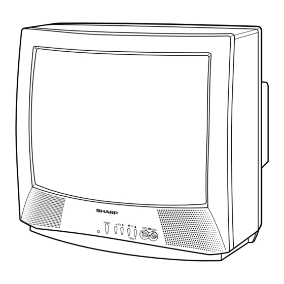
Page 4: Location Of User's Control
20MR10 LOCATION OF USER'S CONTROL Front Panel POWER – V IDEO IN AUDIO MENU VIDEO IN AUDIO IN TERMINALS SENSOR AREA FOR POWER – V OL + REMOTE CONTROL MENU POWER CHANNEL UP/DOWN Press VOLUME UP/DOWN Press again Off. ( ) Selects next higher channel. -
Page 5: Installation And Service Instructions
20MR10 INSTALLATION AND SERVICE INSTRUCTIONS Note: (1) When performing any adjustments to resistor controls and transformers use non-metallic screwdrivers or TV alignment tools. (2) Before performing adjustments, the TV set must be on at least 15 minutes. HIGH VOLTAGE CHECK... -
Page 6: Service Mode
20MR10 For adjustments of this model, the bus data is converted to various analog signals by the D/A converter circuit. Note: There are still a few analog adjustments in this series such as focus and master screen voltage. Follow the steps below whenever the service adjusment is required. - Page 7 20MR10 Below are the adjustments ranges and initial values for FIX VALUE category. FIX VALUE DATA SER VICE ADJUST ITEM INITIAL VALUE POSITION RANGE (Hex) OPTION 1 00-FF OPTION 2 00-FF E-SAVE 00-3F TUNER SETUP 00, 01 R-TONE RD 00-7F...
- Page 8 20MR10 Holding down both the Vol-up/Ch-down buttons on the TV set at service mode for more than 2 seconds will automatically write the above initial values into IC2102 (IC2101). ADJUSTMENT PART REPLACED NOTES NECESSAR Y UNNECESSAR Y IC2001 Data is stored in IC2102 (IC2101).
-
Page 9: Rf Agc Adjustment
20MR10 SER VICE ADJUSTMENT RF AGC Adjustment White Balance Adjustment 1. Receive a good local channel. 1. Receive a good local channel. 2. Enter the service mode signal category and select 2. Select the service adjustment "S12" and set the data the service adjustment "S01". - Page 10 20MR10 Vertical-Size, V-Linearity and V-S Correction Adjustments 1. Receive a good local channel. 2. Enter the service mode DEF category and select the adjustment "D02" for Vertical Size, "D05" for V- Linearity and "D06" for V-S Correction Adjustment. 3. Set in order "D05" for V-Linearity, "D06" for V-S Correction and set the data to get the best linearity.
-
Page 11: Chassis Layout
20MR10 CHASSIS LAYOUT... -
Page 12: Block Diagram
20MR10 BLOCK DIAGRAM... -
Page 13: Schematic Diagrams
20MR10 DESCRIPTION OF SCHEMATIC DIAGRAM WAVEFORM MEASUREMENT CONDITIONS: NOTES: 1. Photographs taken on a standard gated color bar 1. The unit of resistance "ohm" is omitted. signal, the tint setting adjusted for proper color. The (K=k =1000 , M=M ) wave shapes at the red, green and blue cathodes of 2. - Page 14 20MR10 SCHEMATIC DIAGRAM: MAIN Unit NOTE COMBINATION IC201 RH-iX3354CEZZ RH-iX3354CEN1 C211 VCKYCY1HB102K(1000p) C301 VCCCCY1HH470J(47p) VCCCCY1HH220J(22p) C304 VCCCCY1HH470J(47p) VCCCCY1HH220J(22p) C802 VCEA0A1CW106M(10 (16V)) R209 VRS-CY1JF123J(12k) VRS-CY1JF000J(0) R302 VRS-CY1JF332J(3.3k) VRS-CY1JF152J(1.5k) R413 VRS-CY1JF152J(1.5k) VRS-CY1JF222J(2.2K)
- Page 15 20MR10 SCHEMATIC DIAGRAM: CRT Unit...
-
Page 16: Printed Wiring Board Assemblies
20MR10 PRINTED WIRING BOARD ASSEMBLIES PWB-A: MAIN Unit (Wiring Side) - Page 17 20MR10 PWB-A: MAIN Unit (Chip Parts Side)
- Page 18 20MR10 PWB-B: CRT Unit (Wiring Side) PWB-B: CRT Unit (Chip Parts Side)
-
Page 19: Replacement Parts List
VCCCCY1HH470J(47p) VCCCCY1HH220J(22p) C802 — VCEA0A1CW106M(10µ(16V)) in USA: Contact your nearest SHARP Parts Distributor to order. R209 VRS-CY1JF123J(12k) VRS-CY1JF000J(0) For location of SHARP Parts Distributor, Please call Toll- R302 VRS-CY1JF332J(3.3k) VRS-CY1JF152J(1.5k) Free; 1-800-BE-SHARP R413 VRS-CY1JF152J(1.5k) VRS-CY1JF222J(2.2K) IC351 VHiAN7511//-1 J AN7511 MARK : SPARE PARTS-DELIVERY SECTION... - Page 20 20MR10 Ref. No. Part No. Description Code Ref. No. Part No. Description Code PWB-A: DUNTKA358WEX0 D726 VHD1SS119//-1 J Diode MAIN UNIT (Continued) RH-DX0475CEZZ D751 RH-EX0611GEZZ J Zener Diode, 5.1V D753 RH-DX0441CEZZ J Diode VSSTP7NB60F-1 Q702 VS2SC945AQ/-1 J 2SC945AQ RH-DX0110CEZZ D758...
- Page 21 20MR10 Ref. No. Part No. Description Code Ref. No. Part No. Description Code PWB-A: DUNTKA358WEX0 C726 RC-KZ0338CEZZ J 560p 2kV Ceramic C727 VCKYPA2HB472K J 4700p 500V Ceramic MAIN UNIT (Continued) C730 VCEA0A1CW108M J 1000 16V C731 VCEA0A1EW107M J 100 C732 VCKYPA1HF103Z J 0.01...
- Page 22 20MR10 Ref. No. Part No. Description Code Ref. No. Part No. Description Code R654 VRD-RA2BE154J J 150k 1/8W Carbon PWB-A: DUNTKA358WEX0 R655 VRS-CY1JF103J J 10k 1/16W M-Ox. R659 VRN-RL3AB1R0J X 1.0 M-Film MAIN UNIT (Continued) R661 VRN-RL3ABR47J X 0.47 1W...
- Page 23 20MR10 Ref. No. Part No. Description Code Ref. No. Part No. Description Code PWB-A: DUNTKA358WEX0 FH701 QFSHD1013CEZZ J Fuse Holder FH702 QFSHD1014CEZZ J Fuse Holder MAIN UNIT (Continued) J903 QJAKE0205CE09 J Jack, Audio-In R2044 VRS-CY1JF683J J 68k 1/16W M-Ox. QJAKE0159CEZZ R2045 VRS-CY1JF101J J 100 1/16W M-Ox.
-
Page 24: Miscellaneous Parts
— R865 VRS-VU3AE123J J 12k 1W M-Ox. GCOVA0003GJSA X Cover for R/C R866 VRD-RM2HD332J J 3.3k 1/2W Carbon HBDGB1001GJSB X Badge, "SHARP" R867 VRS-CY1JF470J J 47 1/16W M-Ox. JBTN-0003GJSD X Button(Power, Vol-up/down, AH R868 VRS-CY1JF181J J 180 1/16W M-Ox. CH-up/down) -
Page 25: Packing Of The Set
20MR10 Ref. No. Part No. Description Code Ref. No. Part No. Description Code PACKING OF THE SET Polyethylene Bag Operation Manual Infrared R/C Unit Batteries Wrapping Paper Buffer Material FRONT Packing Case Use tape to fix the top side of packing case. - Page 26 Code Ref. No. Part No. Description Code COPYRIGHT © 2001 BY SHARP CORPORATION ALL RIGHTS RESERVED. No part of this publication may be reproduced, stored in a retrieval system, or transmitted in any form or by any means, electronic, mechanical, photocopying, recording, or otherwise, without prior written permission of the publisher.