Table of Contents
Advertisement
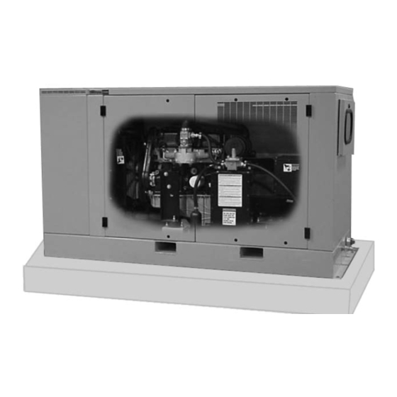
Stationary Standby Electric Generator - 25,000 WATTS
IMPORTANT SAFETY INSTRUCTIONS – Please make certain that persons who are to install, operate and maintain
this equipment thoroughly read and understand these instructions prior to operation. SAVE THESE INSTRUCTIONS
— This manual contains important instructions that should be followed during installation and maintenance of the
generator and battery.
ENGLISH
PP. 1-32
FRANCAIS
pág. 33-52
ESPAÑOL
p. 53-72
WARNING:
Read and understand all safety precautions in this manual and other
manuals included with this product before installing, operating and maintaining this
equipment. Failure to comply with instructions in this manual could result in personal
injury, property damage, and/or voiding of your warranty. Coleman Powermate WILL
NOT be liable for any damage because of failure to follow these instructions.
Record the model and serial numbers of your generator below:
Model Number
____________________
Serial Number
____________________
Date Purchased
____________________
HELPLINE 1-800-445-1805
© 2003 ÂColeman Powermate, Inc. 12-03
OWNERS MANUAL
MODEL: PM402511
200-2313 - Revision C
Advertisement
Table of Contents

Related Manuals for Coleman Powermate PM402511


Summary of Contents for Coleman Powermate PM402511
- Page 1 Failure to comply with instructions in this manual could result in personal injury, property damage, and/or voiding of your warranty. Coleman Powermate WILL NOT be liable for any damage because of failure to follow these instructions.
-
Page 2: Table Of Contents
Table of Contents ..............2 General Safety Instructions . -
Page 3: General Safety Instructions
The following information relates to protecting YOUR SAFETY and PREVENTING EQUIPMENT PROBLEMS. To help you recognize this information, we use the following symbols. Please read the manual and pay attention to these sections. Also read and follow all safety labels on the engine/generator set. If labels are damaged or unreadable, contact product service for replacements. - Page 4 WARNING: CAUTION: Units with broken or missing parts, without The National Electrical Code (NEC) requires the protective housing or covers should never be frame and external electrically conductive parts of operated. Contact your service center for the generator to be connected to an approved earth replacement parts.
-
Page 5: Introduction
The stationary standby electric generator is Be sure to inspect the generator carefully for freight manufactured for our customers to supply reliable loss or damage. If loss or damage is noted at the time of backup power. The generator is a compact unit, delivery, require that the person making the delivery designed to supply the power for your critical needs make note of the loss or damage on the freight bill, or... -
Page 6: Specifications
Rated Wattage - (Standby) 25,000 Watts@1.0PF LPG 22,000 Watts @ 1.0 PF NG Voltage - 120/240 volts Rated Current - 208/104 amps LPG Frequency - 60 HZ Power Factor - 1.0 Max. Ambient Temp Rise - 105°C Insulation class - H Note: Rated wattage is specified at sea level, 60°F ambient temperature, and propane fuel (with 2500 BTU/cuft). -
Page 8: Installation
of four feet of clearance between the generator and any other structure. D D A A N N G G E E R R When placing the generator, the direction of the exhaust should be pointing away from windows, doors and any ventilation system. - Page 9 W W A A R R N N I I N N G G D D A A N N G G E E R R • For fire safety, the generator must be installed • The generator engine exhaust fumes contain and maintained properly.
-
Page 10: Fuel Selection
Per the National Gas Code (NFPA 54 - ANSI 2223.1), a manual shutoff valve in the fuel supply line NATURAL GAS (NG) SETTINGS to the generator is recommended. All fuel system Units are tested with natural gas before they leave installations MUST BE done by a licensed plumber or the factory. -
Page 11: Automatic Transfer Switch
W W A A R R N N I I N N G G This generator must be connected to an automatic transfer switch. The automatic transfer switch detects when a power failure occurs and automatically starts the • Hazardous "backfeed" voltage can cause engine to provide generator power. -
Page 12: Battery Installation
W W A A R R N N I I N N G G Minimum recommended battery size is a BCI Group 26 with a minimum of 550 CCA (Cold Cranking Amps). Place the battery in the battery rack as shown and The electrolyte is a dilute sulfuric acid that is secure using the holddown hardware provided. -
Page 13: Lubrication And Cooling
Check oil level before start-up. The unit is shipped NOTE: Some areas require that a building inspector with the proper type of oil in the crankcase for operation and/or electrical inspector to evaluate the above 40°F. Follow the engine manufacturer’s installation prior to operation. -
Page 14: Generator Control Panel Features
W W A A R R N N I I N N G G Two line by twenty character LCD provides the primary visual interface for metering, alarms, pre- • Place the circuit breaker in the OFF position alarms and protective functions. In the normal mode, when servicing the generator to minimize labels appear above and below the display. -
Page 15: Generator Control Panel Operation
When power failure occurs, a signal will be sent to the generator to start a warm up cycle. After the warm up cycle is completed, the transfer switch will allow the load to be transferred to the generator until it senses that DISPLAY MODE regular utility power has been restored. -
Page 16: Generator Control Panel - Alarms
When the generator control panel senses an All pre-alarm conditions illuminate the red alarm LED abnormal operating condition, an alarm is declared and with a 50% duty cycle at a frequency of 0.5 hertz and the generator set is shutdown. All alarm conditions will sounding the optional audible alarm at the same rate. -
Page 17: 25Kw Wiring Diagram (Cp500)
SCHÉMA DE CÂBLAGE 25KW (CONTRÔLEUR CP 500) DIAGRAMA DE CIRCUITO ELÉCTRICO DE 25 KILOVATIOS (CONTROLADOR CP500) -
Page 18: 25Kw Wiring Diagram (Cp1000)
SCHÉMA DE CÂBLAGE 25KW (CONTRÔLEUR CP 1000) DIAGRAMA DE CIRCUITO ELÉCTRICO DE 25 KILOVATIOS (CONTROLADOR CP1000) -
Page 19: Engine Maintenance
W W A A R R N N I I N N G G • Check oil every 8 hours of operation. • Change oil and oil filter every 100 hours of operation. • Before performing any maintenance, make sure •... -
Page 20: Troubleshooting
SYMPTOM POSSIBLE CAUSE CORRECTIVE ACTION Engine will not crank in Manual mode. 1. Defective Battery. Recharge or replace battery. 2. Blown control panel fuse. Replace fuse. 3. Loose or dirty connections. Check and clean D.C. connections. 4. Defective crank relay. Call customer service. -
Page 21: Limited Warranty
Your Coleman PowerStation™ emergency back up power system generator has been manufactured to stringent guidelines & standards for years of dependable operation & service. Coleman Powermate warrants this product to the original consumer against defects in material and workmanship for a period of 3-Years or 1500 hours, whichever occurs first, from the date of purchase and is not transferable. -
Page 22: Maintenance Log
Always follow the engine manufactures recommendations when performing maintenance. Use this page to track the maintenance which is performed. Noting the time on the hour meter will help in keeping the maintenance schedule. All safety rules must be followed when performing maintenance on the unit. -
Page 23: Parts Drawings / Lists
PLAN DES PIÈCES - SYSTÈME D'ÉCHAPPEMENT \ DIAGRAMA DE PIEZAS - SISTEMA DE ESCAPE Muffler Exhaust Sortie du silencieux Silenciador del escape Muffler Inlet Entrée du silencieux Entrada del silenciador LISTE DES PIÈCES \ LISTA DE PIEZAS Item Part No Article Pièce N°... - Page 24 PLAN DES PIÈCES - BOÎTIER \ DIAGRAMA DE PIEZAS - CARCASA LISTE DES PIÈCES \ LISTA DE PIEZAS Item Part No Article Pièce N° Qté Artículo N.° De Pieza Cantidad Description Description Descripción 115-0206 Lid assembly (includes lid and ..Couvercle (incluant l'isolant sonore) . Conjunto de tapa (incluye la tapa sound proofing material).
- Page 25 PLAN DES PIÈCES - SYSTÈME DE REFROIDISSEMENT DIAGRAMA DE PIEZAS - SISTEMA DE ENFRIAMIENTO LISTE DES PIÈCES \ LISTA DE PIEZAS Item Part No Article Pièce N° Qté Artículo N.° De Pieza Cantidad Description Description Descripción 115-0211 Radiator panel ....Panneau de radiateur ... . Panel del radiador Bolt, HH 1/4-20 X .75 .
- Page 26 PLAN DES PIÈCES - ENSEMBLE DE PORTE \ ESQUEMA DE PIEZAS - CONJUNTO DE LA PUERTA LISTE DES PIÈCES \ LISTA DE PIEZAS Item Part No Article Pièce N° Qté Artículo N.° De Pieza Cantidad Description Description Descripción See page 24 Door assembly .
- Page 27 PLAN DES PIÈCES - SYSTÈME D'ADMISSION \ DIAGRAMA DE PIEZAS - SISTEMA DE COMBUSTIBLE NOTE: Seal all connections with gas tape. Use 2½ wraps minimum. Check all connections under pressure using a soap and water solution. REMARQUE : Sceller toutes les connexions avec du ruban à conduite de gaz.
- Page 28 PLAN DES PIÈCES - GÉNÉRATRICE \ DIAGRAMA DE PIEZAS - GENERADOR LISTE DES PIÈCES \ LISTA DE PIEZAS Item Part No Article Pièce N° Qté Artículo N.° De Pieza Cantidad Description Description Descripción 0059337 Rectifier service kit w/var, dio ..Ens. de réparation redresseur ..Juego de rectificación .
- Page 29 PLAN DES PIÈCES - VUE ÉCLATÉE 25 KW DIAGRAMA DE PIEZAS - DESGLOSE DEL MODELO DE 25 KILOVATIOS LISTE DES PIÈCES \ LISTA DE PIEZAS Item Part No Article Pièce N° Qté Artículo N.° De Pieza Cantidad Description Description Descripción 059-0332 Bolt, M10-1.5 X 25MM .
- Page 30 PLAN DES PIÈCES - ENSEMBLE DE TABLEAU DE COMMANDE DIAGRAMA DE PIEZAS - CONJUNTO TERMINAL DEL PANEL DE CONTROL LISTE DES PIÈCES \ LISTA DE PIEZAS Item Part No Article Pièce N° Qté Artículo N.° De Pieza Cantidad Description Description Descripción 115-0213 Generator end panel .
- Page 31 PLAN DES PIÈCES - VUE ÉCLATÉE DU TABLEAU DE COMMANDE DIAGRAMA DE PIEZAS - DESGLOSE DEL PANEL DE CONTROL LISTE DES PIÈCES \ LISTA DE PIEZAS Item Part No Article Pièce N° Qté Artículo N.° De Pieza Cantidad Description Description Descripción Nut, 1/4-20 nylon stop .
- Page 32 PLAN DES PIÈCES - FIXATION DE LA BATTERIE DIAGRAMA DE PIEZAS - SUJECIÓN DE LA BATERÍA To Starter Au Démarreur Al Arrancador To Engine Block Au Bloc De Moteur Al Bloque Del Motor LISTE DES PIÈCES \ LISTA DE PIEZAS Item Part No Article...