Table of Contents
Advertisement
Quick Links
Advertisement
Table of Contents

Summary of Contents for Lorex Edge LH300 SERIES
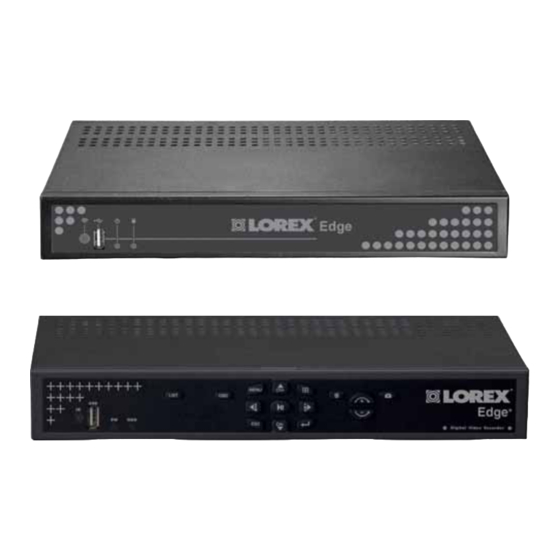
- Page 1 LOREX EDGE NETWORK READY H.264 HIGH PERFORMANCE DIGITAL VIDEO SURVEILLANCE RECORDER INSTRUCTION MANUAL English Version 2.0 Lorex Edge mini LH304 Series Lorex EDGE LH310 Series Lorex-Edge LH320 Series MODEL: LH300 SERIES www.lorextechnology.com © Copyright 2010 Lorex Technology Inc.
- Page 2 Thank you for purchasing the LH300 Series Lorex-Edge H.264 Digital Video Surveillance Recorder. This manual refers to the following models: Lorex Edge mini Lorex Edge Lorex EDGE • LH324 (4-channel) • LH304 (4-channel) • LH314 (4-channel) • LH328 (8-channel) • LH318 (8-channel) •...
- Page 3 Cu s to m e r F e e dba c k i nfo@lorexcorp.c om By Phone: NORTH AMERICA: CUSTOMER SERVICE: 1-888-425-6739 (1-888-42-LOREX) TECH SUPPORT: 1-877-755-6739 (1-877-75-LOREX) MEXICO: 1-866-427-6739 INTERNATIONAL: +800-425-6739-0 (E xa mple: Fro m the U K, dia l 00 in s t ea d of + )
- Page 4 Por Teléfono: Par Téléphone: L’AMÉRIQUE DU NORD: NORTE AMÉRICA: ATENCIÓN AL CLIENTE: 1-888-425-6739 (1-888-42-LOREX) SERVICE À LA CLIENTÈLE: 1-888-425-6739 (1-888-42-LOREX) SUPPORT TECHNIQUE: 1-877-755-6739 (1-877-75-LOREX) SOPORTE TÉCNICO: 1-877-755-6739 (1-877-75-LOREX) MEXICO: 1-866-427-6739 MEXICO: 1-866-427-6739 INTERNACIONAL: +800-425-6739-0 INTERNATIONAL: +800-425-6739-0 (Exemple: À partir du Royaume-Uni, composez 00 au lieu de +)
- Page 5 B E F O R E Y O U S TA R T THIS PRODUCT MAY REQUIRE PROFESSIONAL INSTALLATION LOREX IS COMMITTED TO FULFILLING YOUR SECURITY NEEDS • We have developed user friendly products and documentation. Please read the Quick Start Guide and User Manual before you install this product.
- Page 6 ESTE PRODUCTO PUEDE EXIGIR UNA CE PRODUIT POURRAIT EXIGER UNE INSTALACIÓN PROFESIONAL INSTALLATION PROFESSIONNELLE LOREX S’ENGAGE À SATISFAIRE LOREX SE COMPROMETE A SATISFACER VOS BESOINS SÉCURITAIRES SUS NECESIDADES EN SEGURIDAD • Veuillez lire le guide de démarrage rapide et le •...
-
Page 7: Important Safeguards
Important Safeguards In addition to the careful attention devoted to quality standards in the manufacture process of your video product, safety is a major factor in the design of every instrument. However, safety is your responsibility too. This sheet lists important information that will help to assure your enjoyment and proper use of the video product and accessory equipment. - Page 8 Service 13. Servicing - Do not attempt to service this video 19. Cleaning - Unplug the video product from the wall equipment yourself as opening or removing covers outlet before cleaning. Do not use liquid cleaners or may expose you to dangerous voltage or other aerosol cleaners.
-
Page 9: General Precautions
General Precautions 1. All warnings and instructions in this manual should be followed. 2. Remove the plug from the outlet before cleaning. Do not use liquid aerosol detergents. Use a water dampened cloth for cleaning. 3. Do not use this unit in humid or wet places. 4. -
Page 10: System Features
• PC (Microsoft Windows™ 7/Vista/XP compatible) using Internet Explorer® browser • Apple Mac compatible using the Safari browser for multi-channel live viewing • Free LOREX DDNS (Dynamic Domain Name Service) for advanced remote connectivity at all times • Email notification of events Recording capacity may vary based on recording resolution &... -
Page 11: Table Of Contents
Lorex EDGE mini: Front Panel ........ - Page 12 Playback Mode ..............24 Taking Screenshots .
- Page 13 How port forwarding works ..........68 Lorex Auto Port Forwarding Wizard ......69 Installation .
- Page 14 Downloading the Lorex Live Application ........
-
Page 15: Getting Started
GETTING STARTED The system comes with the following components: EDGE + DVR (LH320) EDGE DVR (LH310) EDGE mini DVR (LH304) DVI / VGA Adapter USB Mouse DVI / VGA Adapter USB Mouse USB Mouse (8 & 16 channel models only) Remote Control Flex-IR Extender Flex-IR Extender... -
Page 16: Lorex Edge Mini: Front Panel
Getting Started Lorex EDGE mini: Front Panel 1. USB port: Connect a USB flash drive for data backup and firmware updates (download from website). 2. Power Indicator: LED indicator for system power. 3. HDD Indicator: LED indicator for internal hard drive. -
Page 17: Lorex Edge: Front Panel
Getting Started Lorex EDGE: Front Panel All models 1. IR Receiver: Internal IR receiver for the remote control. 2. USB port: Connect a USB flash drive for data backup and firmware updates (download from website). 3. Power Indicator: LED indicator for system power. When system is powered on, LED is lit red. - Page 18 Getting Started Lorex EDGE: Rear Panel 8-channel 1. Video In: BNC input ports for 8 BNC cameras. 2. Audio In: Input ports for audio enabled cameras. 3. Alarm I/O: Input/output port for alarm / relay (D-sub 9 connector required—not included).
-
Page 19: Lorex Edge+ : Front Panel
Getting Started Lorex EDGE : Front Panel All Models 1. IR Receiver: Internal IR receiver for the remote control. 2. USB port: Connect a USB flash drive for data backup and firmware updates (download from website). 3. Power Indicator: LED indicator for system power. When system is powered on, LED is lit red. -
Page 20: Lorex Edge+: Rear Panel
Getting Started Lorex EDGE : Rear Panel 4-channel 1. DC 12V: Port for 12V DC, 2.5A power adapter (included). 2. DVI: Port to connect a DVI monitor (not included). 3. Audio In: Input ports for audio enabled cameras. Audio Out: Output for two audio channels. - Page 21 Getting Started 16-channel 1. Video In: BNC input ports for 16 BNC cameras. 2. Audio In: Input ports for audio enabled cameras (not included). Audio Out: Output for two audio channels. 3. Alarm Block: Input/output port for alarm / relay devices (i.e. PTZ cameras and sensors, not included).
-
Page 22: Basic Setup
Getting Started Basic Setup The system is designed to mount to the back of most LCD monitors with a VESA mount. If desired, you can mount it to a wall or leave the system in a standard horizontal or vertical position. ATTENTION: You can only mount the system to an LCD monitor that has a VESA mount and an independent stand, with clear access to the VESA mount holes. -
Page 23: System Passwords
Getting Started System Passwords Depending on your system model, the default user name (ID) and password is different. Refer to the tables below for details on the default system user IDs and passwords. Remote/LAN Viewing Local DVR Access 4/ 8/ 16 Channel 4 Channel 8 &... -
Page 24: Remote Control
Getting Started Remote Control The remote control is the secondary input device for navigating the system’s graphical user interface. To use the remote control: LIST : Open the Event List menu. : Show/hide the on-screen display. 3. Primary controls: MENU •... -
Page 25: Starting The System
Starting the System STARTING THE SYSTEM To power the system ON: • Connect the power cable to the DC 12V port on the rear panel of the system At startup, the system performs a basic system check and runs an initial loading sequence. After Live Mode a few moments, the system loads a live display view ( NOTE: Make sure all cameras and cables are properly connected prior to powering on the... - Page 26 Starting the System 3. HDD Status: Displays the recording space consumed on the hard disk (%) and the size of the pre-installed hard drive. For example, 250 GB. 4. Camera Status: Displays channel number, recording status, frame rate, and video quality. 5.
-
Page 27: 8/16-Channel
Starting the System 8/16-channel Figure 4.2 Live viewing with onscreen display (16-channel model shown) 1. Display Screen: Shows live and recorded video—single, quad, and split-screen (16-split on only 16-channel model 2. Camera Number/Title: You can set the display to show the Camera Number, Title, or show no title. - Page 28 Starting the System • : Click to open the Split-Screen Selector; from full-screen (Live Mode only), click once to view quad, click again to open Split-Screen Selector. See “Using the Split-Screen Selector” on page 15. • : Click to open the system Main Menu. See “Using the Main Menu” on page 29. •...
-
Page 29: Using The Split-Screen Selector
Starting the System Using the Split-Screen Selector 8/16-channel models only ATTENTION: Split-Screen Selector is only available on If your system has 8/16-channels, you must choose a split-screen configuration using the Split-Screen Selector built into the system’s interface. The Split-Screen Selector allows you to choose the grid configuration for the main display during live viewing and playback: quad, 9-split, or 16-split (16-channel only... -
Page 30: Flexible Camera Assignment
Starting the System Flexible Camera Assignment You can re-assign camera channels to different positions. For example, you can duplicate the video feed from channel 1 onto channel 2.This is useful if you wish to re-arrange the position of each channel. NOTE: This feature is avaliable on 8/16 channel systems only. -
Page 31: Setting The Date And Time
SETTING THE DATE AND TIME It is highly recommended to immediately set the date and time when first setting up your system. To set the date and time: 1. Click to open the Main Menu. 2. Click to open the Setup menu. 3. -
Page 32: Recording
RECORDING By default, the system is set to immediately record video from connected cameras in Continuous Record Mode. You can set the system to stop recording once the hard drive is full, or to continually record by overwriting previously recorded data. For more details, see “Record” on page 31. Event Recording The system includes three modes of event recording: •... -
Page 33: Playback
PLAYBACK View recorded video on the system through playback mode. The playback time appears in the bottom-right corner of the screen. Figure 6.0 Playback display view To begin playback: 1. From the main screen, click Playback mode opens. NOTE: If toolbar is not visible, first click 2. -
Page 34: Playback Markers
Playback Playback Markers During playback, click anywhere in the playback bar to set a playback marker. Use this orange-colored marker for reference in future searches. Additional Search Markers The Playback bar can also be populated with other multi-colored markers. These markers are part of the Smart Search functionality of the system. -
Page 35: Event List
EVENT LIST The system features an Event List to organize and search for recorded video on the system. The Event List, coupled with the Smart Search icons, allows you to search for recorded data on your system quickly and easily. NOTE: The system can save a maximum of 4096 events (4-channel) / 8192 events (8 &... -
Page 36: Smart Search
Event List Smart Search Click the Smart Search icons to filter data according to events. These Smart Search icons are mirrored as event markers in Playback and Backup modes. Figure 7.1 Smart Search Icons Event Details The event details (event number, camera on/off, filter type, date & time, and event source) immediately match the list of events. -
Page 37: Searching For Recorded Data
Event List Searching for Recorded Data You can use the Event List from Live Mode and Playback Mode to search for recorded data on your system. Live Mode To search for data: 1. From the main screen, click . The Event List opens. 2. -
Page 38: Playback Mode
Event List Playback Mode To search for data: 1. From the main screen, click . Playback mode opens. NOTE: If toolbar is not visible, first click 2. Click . The Event List opens. NOTE: Click for Edge 8/16-channel models. 3. Under Channel Filter, click to view events for channels, or click the Channel icons individual... -
Page 39: Taking Screenshots
TAKING SCREENSHOTS 8/16-channel models only ATTENTION: If your system has 8 or 16 channels, you can take screenshots (screen captures) of the main display of your system. You can take a screenshot at any time: during live viewing, search, and playback, or in any system menu. -
Page 40: Using Screenshots
Taking Screenshots Using Screenshots Once you have taken screenshots, you need to connect the USB flash drive to a PC to view, print, or archive the images. To use screenshots: 1. Connect the USB flash drive to a USB port on your PC. In the AutoPlay window, select Open folder to view files. -
Page 41: Managing Passwords
MANAGING PASSWORDS Refer to the tables below for the user name (ID) and password required to log in to your system: Remote/LAN Viewing Local DVR Access 4/ 8/ 16 Channel 8 & 16 Channel 4 Channel LEVEL PASSWORD LEVEL PASSWORD LEVEL PASSWORD GUEST... -
Page 42: Changing Passwords
Managing Passwords Changing Passwords You need to be logged in as the administrator in order to change passwords on the system. To change passwords: 1. Click to open the Main Menu. NOTE: In older firmware models, click 2. Click . The Setup menu opens. 3. -
Page 43: Using The Main Menu
Using the Main Menu USING THE MAIN MENU Depending on your DVR model: • Click to open the Main Menu OR • Click to open the Main Menu NOTE: If passwords are enabled on the system, you need to select your user ID and enter the four-digit numerical password to open the Main Menu. -
Page 44: Camera
Using the Main Menu Camera Setup Configure display settings for each camera. Set date/time, system language, passwords, and view system information. Figure 10.0 Camera menu To configure camera color settings: Figure 11.0 System Setup 1. From the Main Menu, click . -
Page 45: Record
Using the Main Menu • Fan Speed: Click to set the fan speed to To configure record settings: Low, Middle, or High. The higher the fan 1. From the Main Menu, click . The speed the cooler the HDD temperature (8/ only Record menu opens. -
Page 46: 8/16-Channel
Using the Main Menu • Record Mode: Select one of the following: Overwrite: The system continues recording when the Single-Way: The system internal hard drive is full by stops recording when the internal overwriting the oldest recorded hard drive is full. data. -
Page 47: Schedule
Using the Main Menu Schedule Quality: Click under each camera and select 1, 2, 3, 4, or 5. 4/8/16-channel Set an hourly, daily, and/or weekly recording schedule. Figure 12.6 Set image quality: 1 basic ~ 5 excellent Audio: Click under each camera and select either O to enable audio to disable audio. -
Page 48: Format Hdd
Using the Main Menu Format HDD Alarm If you replace the pre-installed hard drive, the 4-channel must new drive be formatted in order to Configure alarm and motion detection function properly with the system. settings. ATTENTION: Formatting the HDD erases all data This step cannot on the hard disk. - Page 49 Using the Main Menu Alarm Input & Output Menu 2. Click to assign an Event notification (Motion, VLoss, Alarm, HDD ON/OFF) to an Alarm-Out notification (Buzzer, Alarm Full-Screen, Label, Alarm Out 1). • Buzzer: Select O to enable the system Figure 13.0b Alarm Input &...
-
Page 50: 8/16-Channel
Using the Main Menu 8/16-channel press the buttons on the remote/front panel. Select to disable the beep. • Alarm Input & Output: Click to open the Alarm Input & Output menu. Figure 13.1 Alarm menu (8/16-channel) To configure the alarm settings: Figure 13.2 Alarm Input &... -
Page 51: Motion
Using the Main Menu • Response Duration: Select the time (in 3. Click Motion. Select the camera you want seconds) for the system to record after to configure motion detection. The motion a triggered alarm or motion event: grid appears for the selected camera. 1~255. -
Page 52: Backup
Backup 4. Click Yes to format the hard disk or click No to cancel. Set start and stop times for recorded video data you wish to copy to a connected USB flash drive (not included). NOTE: The system supports most brands of Figure 14.1 Confirm formatting USB flash drives from 128 MB ~ 8 GB. -
Page 53: Confirming Backup
Confirming Backup Setting Quicktime as a default media player To verify that the file has been properly backed It is recommended to set Quicktime as your default media player. This allows you to double-click on a backed up video file, and 1. -
Page 54: Lan
Using the Main Menu Easy Connect Use the Easy Connect menu to enable Easy Configure network settings. Connect, and view the Easy Connect log. From the Main Menu, click . The LAN For details on connecting to your system menu opens. remotely using Yoics, see “Remote Viewing Using Easy Connect”... -
Page 55: Lan Password
Using the Main Menu LAN Password Upgrading Firmware Use the LAN Password to control Remote Firmware upgrades can provide improved Viewing access for Guest, User, and functionality to your system. You can download Administrator profiles. The LAN password is these free upgrades from required if using the built-in browser-based www.lorextechnology.com. -
Page 56: Changing Ports On Your System
Changing Ports On Your System CHANGING PORTS ON YOUR SYSTEM For added security, we strongly recommend any desired changing HTTP port 80 on the system to port —the port must not blocked by your Internet If you change the default port on the system from 80 to a different value, you MUST enter http:// and service provider (ISP). -
Page 57: Local Viewing
Changing Ports On Your System You must now include the new HTTP port number in the URL when logging in to your system with Internet Explorer. NOTE: Requires Internet Explorer 6 or later. Local Viewing: To log in using the new port number: 1. -
Page 58: Remote Viewing
Changing Ports On Your System Remote Viewing: You should now be able to access your system from your local network. Prior to using remote viewing, you must log in to your system and enter the DDNS information from your Lorex DDNS confirmation email. NOTE: We strongly recommend registering for Lorex’s free DDNS service prior to using remote viewing. - Page 59 Changing Ports On Your System listed, please refer to your router's manual or contact your router's manufacturer for assistance. Now that you have configured your DDNS settings, you should be able to log in to your system from a remote PC (i.e. a PC not on your local network). NOTE: 4/8/16-channel : The PC used for remote viewing requires Internet Explorer 6 or later.
-
Page 60: Remote Access: Dvr Netviewer
REMOTE ACCESS: DVR Netviewer REMOTE ACCESS: DVR NETVIEWER DVR Netviewer is the built-in browser-based remote surveillance software that allows you to access your system from any PC with an Internet connection. Figure 16.1 Main screen (4-channel) Figure 16.0 DVR Netviewer Main Screen (8/16-channel) System Requirements Prior to using DVR Netviewer, make sure your PC meets or exceeds the following system requirements:... -
Page 61: Netviewer: Basic Layout
REMOTE ACCESS: DVR Netviewer Netviewer: Basic Layout 4 Channel Figure 17.0: Four channel Netviewer. 16 Channel Figure 17.1: Sixteen channel Netviewer. Network User Profiles In order to login to DVR Netviewer, you need a network user ID and password. Use the following default network user IDs and password to login to DVR Netviewer: Remote/LAN Viewing 4/ 8/ 16 Channel... -
Page 62: Dvr Netviewer Main Screen
REMOTE ACCESS: DVR Netviewer DVR Netviewer Main Screen 4-channel Upon login, the DVR Netviewer main screen appears in your browser. By default, DVR Netviewer opens in Live Viewing mode. Figure 19.0 DVR Netviewer main screen 1. Display screen: Displays channels in single channel full-screen, or all channels in quad split-screen. -
Page 63: 8/16-Channel
REMOTE ACCESS: DVR Netviewer 8/16-channel Figure 19.1 DVR Netviewer main screen (16-channel shown) 1. Display screen: Displays channels in single channel full-screen, or all channels in quad split-screen. 2. Date/Time: Present date and time on the networked system. 3. Modes: LIVE •... -
Page 64: Live Viewing
Live Viewing 3. Click to open a pop-up calendar to select the date and time. By default, DVR Netviewer launches in Live Viewing mode. 4. Click to control playback. Using the Pop-Up Calendar Channel buttons Figure 20.0 Live Viewing controls (4-channel shown) Drag slider to adjust time To use Live Viewing:... -
Page 65: Backup
REMOTE ACCESS: DVR Netviewer Backup 3. Under Start Time, click to open the pop-up calendar and enter a date and Use Backup to copy recorded video data from time. Click the SET button. your DVR to your PC or Mac. •... -
Page 66: Setup
4. Click Apply to save your settings. Figure 23.0 System Status in Setup menu. DDNS Lorex provides a free DDNS service for use with your DVR. A DDNS account allows you to Bitrate set up a web site address that points back to your Local Network. -
Page 67: System Status
Obtain this information from the confirmation email after registering for the free To return to DVR Netviewer main screen: Lorex DDNS service. 4. Under DDNS Domain Name, enter only the • From the Setup menu, click first portion of your DDNS domain from the confirmation email. -
Page 68: Mail
Figure 23.6 Default email notification setup (8/16-channel only) NOTE: By default, Mail Notification is designed to work with Lorex DDNS. You must first register with Lorex DDNS for email notification to work. However, Figure 23.7 Camera title setup (8/16-channel only—... -
Page 69: Setting Up Local And Remote Viewing
Setting up Local and Remote Viewing SETTING UP LOCAL AND REMOTE VIEWING You can connect the system to a network for local or remote viewing. Once connected, you can access your system locally or remotely using the DVR Netviewer with Internet Explorer™ (PC) or Safari™... -
Page 70: Viewing Your System Through A Local Area Network
Setting up Local and Remote Viewing Viewing your system through a Local Area Network To connect to a network: 1. Power off your system by disconnecting the power cable from the rear panel. 2. Connect an Ethernet cable (included) to the LAN port on the rear panel of the system. Connect the other end of the Ethernet cable to an empty LAN port (usually numbered 1~4) on your router. -
Page 71: Connecting To Your System
Setting up Local and Remote Viewing Connecting to your system Once you have your system’s IP and HTTP Port number, you can view your system locally through the same local network. To view your system locally: 1. Open Internet Explorer or Safari (Mac users) 2. -
Page 72: Connecting To The System Using Safari (Mac)
Setting up Local and Remote Viewing ® 4. You must install the ActiveX plug-in for DVR Netviewer to function. Click the attention bar at the top of the main page and select Install ActiveX Control. DVR Netviewer will reset. Figure 24.5 Click the ActiveX attention bar 5. - Page 73 Setting up Local and Remote Viewing • A plug-in window opens. Figure 24.8 Safari plug-in prompt. 3. Click OK to continue. 4. Click the Safari Plug-In Download link near the bottom of the window. Download version 10.5 or 10.6 of the firmware accordingly to your operating system version.
-
Page 74: Setting Up Remote Connectivity
2. Create a Lorex DDNS account. 3. Enable DDNS on your system. • For details on the Auto Port Forwarding Wizard, see “Lorex Auto Port Forwarding Wizard” on page 69. • For details on creating a DDNS account, see “Setting Up DDNS” on page 76. -
Page 75: Remote Viewing Using Easy Connect
Remote Viewing Using Easy Connect REMOTE VIEWING USING EASY CONNECT Yoics is an online service that allows you to connect and manage your Lorex devices online without router configuration. Register with Yoics to remotely view your cameras on your DVR anywhere in the world. -
Page 76: Enabling Easy Connect
Remote Viewing Using Easy Connect Enabling Easy Connect Easy connect is included in firmware version 7.21.02_18717 (4-channel) or 1.30.09_18712 (8/16-channel) or above. To check your firmware version, from the Main Menu, click , and then click Information. Your firmware version is listed under S/W. You may need to upgrade your system to the latest firmware to enable Easy Connect. -
Page 77: Download The Firmware From The Lorex Website
Remote Viewing Using Easy Connect Download the firmware from the Lorex website 1. Go to www.lorexcctv.com and search for LH3xx (where xx is your model #). Download the latest firmware relevant to your model number. NOTE: 4-channel firmware is different from the 8 & 16-channel firmware. -
Page 78: Registering For An Easy Connect Account
After you upgrade your DVR with the Yoics Easy Connect firmware, you must create a Yoics account and register your device with Yoics. To register your DVR with Yoics: You must connect your DVR to a router 1. Go to http://lorex.yoics.com and register for connected to the internet before an account. registering a Yoics account. - Page 79 Click Register after you complete the form. Figure 25.5: Yoics registration screen. 2. After you log into Yoics, a message box indicates that a device has been detected by Yoics. Click to continue. A "Register New Devices" window opens. Complete Registration NOTE: If you do not see this pop-up...
-
Page 80: Connecting To Your Dvr Using Easy Connect
3. Under Yoics Device Name, enter in the desired name for your DVR. In this example, we named the system name to "DVR". Click to continue. Register Now Enter desired name of your DVR here. Figure 25.7: Register New Devices window. Your device appears on the left side bar under "My Stuff". : You do not have to click the Upgrade Now button. - Page 81 3. An ActiveX toolbar opens in the browser. Click the ActiveX tool bar and click Install ActiveX to continue. Control Click Install ActiveX Control. NOTE: Your browser settings may prevent you from installing ActiveX. Adjust your browser settings to allow for ActiveX installation.
-
Page 82: How Port Forwarding Works
Remote Viewing Using Easy Connect How port forwarding works You need to enable port forwarding on your router to allow for external communications with your system for the following port: • 80 (HTTP port) NOTE: any desired For added security, we strongly recommend changing HTTP port 80 on the system to port —the port must not blocked by your Internet service provider (ISP). -
Page 83: Lorex Auto Port Forwarding Wizard
Forwarding Wizard to port forward the required ports. Installation To install the Lorex Auto Port Forwarding Wizard: 1. Insert the system’s software CD, and follow the instructions to launch the Lorex Auto Port Forwarding Wizard software. • The installation window opens. -
Page 84: Obtaining Your Router Model Number And Version
5. Click the Next button and then click Finish to complete the software installation. Finish button Figure 27.2 Completing the installation. 6. Double-click the Lorex Auto Port Forwarding shortcut ( )from your desktop to start the program. Obtaining Your Router Model Number and Version On most routers, the model and version number can be found underneath the router, printed on a sticker. -
Page 85: Configuration
2. Your router’s user name and password 3. Your Lorex device’s IP address 4. Your Lorex device’s port numbers that require port forwarding Initial Startup: Select language 1. Click the Language drop-down menu and select a language (English, French, Spanish). Click the Start button to continue. -
Page 86: Step 2: Enter Your Router Settings
Figure 27.7 Router settings window. 4. Under IP, enter the IP address of your Lorex device. • To find your system IP, exit to the main viewing mode, and then press the INFO button on your remote, or press the RETURN button on the front panel of the system. -
Page 87: Step 3: Update The Router Settings
Step 4: Test your connection 1. Click the Test Your Connection button. • Your system’s default browser opens and connects to your Lorex device. NOTE: Ensure that Internet Explorer is your system’s default internet browser. NOTE: A window opens that prompts you to enter in your DVR’s user name and password (do not enter your DDNS log in information). -
Page 88: Scenario A: Router/Modem Combination + Router
• The "Possible 1st Router" refers to the router directly connected to your system. This is the router that requires the port forward information. • The "Possible 2nd Router" refers to the router immediate to the internet connection. This is the router that requires you to configure a DMZ host connection. -
Page 89: Example
Lorex Auto Port Forwarding Wizard Configuring a DMZ host connection Example • Connect to "Router 1" on your network (referred DMZ stands for Demilitarized Zone. Enabling a DMZ to as "Possible 1st Router" in the Auto Port IP on your router enables one of the routers to pass Forwarding Wizard). -
Page 90: Setting Up Ddns
Setting Up DDNS Lorex offers a free DDNS service for use with your system. A DDNS account allows you to set up a web site address that points back to your Local Network. The following outlines how to set up your free Lorex DDNS account. -
Page 91: Enabling Ddns On Your System
6. In the corresponding text fields, enter your DDNS username and password. NOTE: Obtain this information from the confirmation email after registering for the free Lorex DDNS service. 7. Under DDNS Domain Name, enter only the first portion of your DDNS domain from the confirmation email. -
Page 92: Networking Checklist
Lorex Auto Port Forwarding Wizard Networking Checklist Use this checklist to confirm you have completed all the steps of the Network Setup. I have the following: • High-Speed Internet • Router • Ethernet cable (included with the system) • Computer with Internet Explorer 6 or later I have turned off the system and performed the following: •... - Page 93 5. Under DDNS Select, click the drop-down menu and select http://lorexddns.net 6. In the corresponding text fields, enter your DDNS username and password. NOTE: Obtain this information from the confirmation email after registering for the free Lorex DDNS service. 7. Under DDNS Domain Name, enter only the first portion of your DDNS domain from the confirmation email.
-
Page 94: Mobile Connectivity
For details, "see “Setting Up DDNS” on page 76. • The Port Number of your DVR For details, see “Lorex Auto Port Forwarding Wizard” on page 69 of your owner’s manual for details on port forwarding, and retrieving your system’s port number. By default, the port number is... -
Page 95: Mobile Connectivity On The Iphone / Ipad
FREE Install • The App will install on your iPhone / iPad and you will see the following Lorex Live / Lorex Live Plus icon on your application list: Connecting To Your DVR - iPhone Users To connect to your DVR on your iPhone: 1. -
Page 96: The Lorex Live Interface
DVR and displays a streaming video in a single channel view. Tap the screen to orient video in landscape mode. Figure 30.1 Main viewing window. The Lorex Live Interface Data transmission rate (bits per second) Video refresh rate (Frames Per Second) Tap to see different cameras. -
Page 97: Connecting To Your Dvr - Ipad Users
Mobile Connectivity Connecting To Your DVR - iPad users To connect to your DVR on your iPad: 1. Touch to start the application. The Setup screen appears. 2. Enter your DVR DDNS address in full (i.e tomsmith.lorexddns.net), DVR Port Number, DVR ID and DVR Password. -
Page 98: Mobile Connectivity On Windows Mobile
Mobile Connectivity Mobile Connectivity on Windows Mobile To connect to your DVR using Windows Mobile smartphones, you need to download and install the Mobile View application. To download Mobile View: 1. Go to www.lorextechnology.com and search for LH3xx (where xx is the model #). Download the Mobile View application. -
Page 99: Mobile Connectivity On The Blackberry
Mobile Connectivity Mobile Connectivity on the Blackberry Requirements: • Blackberry 3G 9000 or higher You must port forward • Blackberry Desktop Manager Software your router before you can connect to your system using a mobile device (i.e Prerequisites: Blackberry 3G 9000) •... - Page 100 Mobile Connectivity Enabling APN (Access Point Name) In order for Mobile View to run, you must enable APN (Access Point Name) on your Blackberry. Contact your service provider for your Blackberry’s APN name. To enable APN: 1. Press the Menu button ( 2.
-
Page 101: Connecting To Your Dvr
Mobile Connectivity Connecting to your DVR You can view your DVR remotely using your provider’s 3G Network. Data charges may apply. See your cellphone carrier’s network data plan for details. 1. Press the Menu button ( 2. Open the Downloads folder. Downloads folder Figure 30.10 Opening the Downloads folder. -
Page 102: Viewing Tips
Mobile Connectivity Viewing Your DVR Once you have entered your DVR’s system information, you can begin live viewing. You can view a single channel of video stream of your DVR. Split screen view is not avaliable. NOTE: If you exit Mobile View, you must wait 30 seconds before starting Mobile View again. To change the channel view: •... -
Page 103: Appendix A: System Specifications
Appendix A: System Specifications APPENDIX A: SYSTEM SPECIFICATIONS Specifications are shared among 4/8/16-channel models unless specifically note d. EDGE SERIES DVR Description Specification 16CH Hard disk capacity Maximum 1 HDD up to 1TB, 100% duty cycle Operating system Linux (embedded) Backup USB flash drive (front panel port only... -
Page 104: Appendix A: System Specifications (Cont'd.)
Appendix A: System Specifications Appendix A: System Specifications (cont’d.) EDGE SERIES DVR Description Specification 16CH Alarm inputs 4 x TTL 4 x TTL, programmable as NC/NO Alarm outputs 1 x relay with NO/NC contact Activity detection 4 x 3 grid, sensitivity levels: 100 8 x 6 grid, sensitivity levels: 100 Remote functions Live view, live recording, search, setup, backup... -
Page 105: Edge+And Edge Mini Specifications
Appendix A: System Specifications Edge and Edge Mini Specifications SYSTEM Operating System Linux (embedded) Pentaplex Simultaneous View, Record, Playback, Backup & Remote Monitoring Number of Channels 4 Channel (Edge mini) 4/8/16 Channel (Edge & Edge+) INPUTS/OUTPUTS Video IN 4/8/16 x 1Vp-p, 75ohms, BNC DVI Out* DVI compatible. - Page 106 Mobile connectivity Blackberry™ - 9000 Series and above, iPhone™ - 3.1.2 and above, Windows Mobile™ smart phones - 6.0 and above touch screen smart phones DDNS Free Lorex DDNS Web Server Port Programmable by User Network Protocol LAN, DHCP, Dynamic IP, DDNS...
- Page 107 41° ~ 104° F / 5° ~ 40° C Humidity 10 ~ 75% NC As our products are subject to continuous improvement, Lorex Technology Inc. and its subsidiaries reserve the right to modify product design, specifications, and prices without E&OE...
-
Page 108: Appendix B: Connecting Motion / Alarm Devices
Appendix B: Connecting Motion / Alarm Devices APPENDIX B: CONNECTING MOTION / ALARM DEVICES You can enable Motion Detection and Alarm control from the Main Menu. You can also connect additional motion sensor devices to the system (i.e. motion sensors, door/window sensors) with a D-sub 9 connector (not included). - Page 109 Appendix B: Connecting Motion / Alarm Devices Installing a Sensor on EDGE series You can connect external alarm input and alarm output devices to the system (i.e. motion sensors, door/window sensors). Use a motion detector or sensor to send a signal to the system to begin camera viewing and recording on the matching camera channel (when enabled in the Menu);...
- Page 110 Appendix B: Connecting Motion / Alarm Devices Installing a PTZ (Pan, Tilt, Zoom) Camera on EDGE LH320 series You can connect RS-485 PTZ cameras (not included) to the PTZ Control Block on the rear panel of the system (LH320 series only). Video (BNC) D+ (TX+) D- (TX-)
-
Page 111: Ptz Control Interface
Appendix B: Connecting Motion / Alarm Devices 5. Beside Camera ID, select the camera’s system address. This number is shown when the PTZ camera first boots up. • This number may sometimes be called "Dome ID". 6. Click Control Enable, and use the mouse scroll wheel to select O. 7. - Page 112 Appendix B: Connecting Motion / Alarm Devices NOTE: You can also drag the cursor on the screen during full screen mode, to pan and tilt the camera. Drag cursor on screen to pan/tilt the camera Configuring PTZ Pre-sets Saving a preset: 1.
-
Page 113: Appendix C: Connecting Audio
Appendix C: Connecting Audio APPENDIX C: CONNECTING AUDIO You can listen to, and record live audio on the system one channel at a time. EDGE Series AUDIO CAPABLE CAMERAS (not included) LINE AUDIO / AMPLIFIED SPEAKERS (not included) EDGE Series AUDIO CAPABLE CAMERAS (not included) LINE AUDIO / AMPLIFIED SPEAKERS... - Page 114 Appendix C: Connecting Audio EDGE mini AUDIO CAPABLE CAMERAS (not included) LINE AUDIO / AMPLIFIED SPEAKERS (not included) To connect audio: 1. Connect RCA audio cables from an audio capable camera(s) to the AUDIO IN 1 / 2 ports on the rear panel.
-
Page 115: Appendix D: Full Connectivity Diagram
Appendix D: Full Connectivity Diagram APPENDIX D: FULL CONNECTIVITY DIAGRAM The following diagram outlines a general set of connections available with the system. EDGE Series (Not Included) (Not Included) Flex IR Extender (Not Included) USB Port LINE IN AUDIO from Audio Capable Cameras/ VGA MONITOR AMPLIFIED... - Page 116 Appendix D: Full Connectivity Diagram EDGE Series (Not Included) LINE IN AUDIO from Audio Capable Cameras/ (Not Included) AMPLIFIED SPEAKERS Flex IR Extender (not included) (Not Included) USB Port BNC CAMERAS DVI/VGA MONITOR* (not included) 16 channel model shown *DVI to VGA converter included.
- Page 117 Appendix D: Full Connectivity Diagram EDGE mini Series (Not Included) LINE IN AUDIO from (Not Included) Audio Capble Cameras/ AMPLIFIED SPEAKERS (not included) USB Port* Flex IR Extender BNC CAMERAS (Optional, not included) VGA MONITOR (not included) 16 channel model shown...
-
Page 118: Appendix E: Replacing The Hard Drive
Appendix E: Replacing the Hard Drive APPENDIX E: REPLACING THE HARD DRIVE EDGE Series DVR The system comes with a pre-installed 3.5" SATA hard drive. You can expand the system with a replacement single hard drive up to 2 terabyte (TB). Make sure that the system is OFF and the power cable has been disconnected before changing the hard drive. - Page 119 Appendix E: Replacing the Hard Drive Replacing the Hard Drive To replace the hard drive: 1. Firmly connect the power and data cables to the replacement SATA hard drive—each cable can only connect in one way. 2. Carefully place the hard drive in the housing: insert towards the front panel, lower the drive, then slide toward the rear panel.
-
Page 120: Edge Dvr
Appendix E: Replacing the Hard Drive EDGE Make sure that the system is OFF and the power cable has been disconnected before changing the hard drive. Removing the hard drive To remove the hard drive: 1. Remove the screws from the top panel and side panels of the housing. Remove the 4 side panel screws Side view Top view... - Page 121 Appendix E: Replacing the Hard Drive Replacing the hard drive To replace the hard drive: 1. Slide the new hard drive into the mounting bracket upside down. 2. Secure the hard drive to the mounting bracket using the four screws. Mount the hard drive to the metal bracket using the four screws.
- Page 122 Appendix E: Replacing the Hard Drive EDGE Mini DVR Make sure that the system is OFF and the power cable has been disconnected before changing the hard drive. Removing the hard drive To remove the hard drive: 1. Remove the screws on the side panels. Remove the single screw on the top and bottom panel of the system.
- Page 123 Appendix E: Replacing the Hard Drive Replacing the hard drive To replace the hard drive: 1. Place the hard drive on the mounting bracket. NOTE: Ensure the SATA data and power ports face the back panel. Back panel 2. Plug in the SATA data and power connector. 3.
-
Page 124: Formatting The Hard Drive
Appendix E: Replacing the Hard Drive Formatting the Hard Drive must If you replace the pre-installed hard drive, it be formatted in order to function properly with the system. ATTENTION: Formatting the HDD all data This erases on the hard disk. step cannot be undone To format the hard disk: 1. -
Page 125: Troubleshooting
Troubleshooting TROUBLESHOOTING When a malfunction occurs, it may not be serious and can be corrected easily. The following describes the most common problems and solutions. Please refer to the following before calling Lorex Technical Support: Error Possible Causes Solutions • System is not •... - Page 126 Setup; click the Mail tab; under SMTP Status, select On • If using the default setting, you • In the SMTP User field, enter your Lorex DDNS have not entered your Lorex user name; in the SMTP Password field, enter your...
- Page 130 CONNECT . PROTECT Enhance your security with genuine Lorex Cameras, Digital Video Recorders, Integrated Systems and Accessories. Order whatever you need at www.lorextechnology.com or call 1-888-42-LOREX (1-888-425-6739) Warehouse Office Restaurant Convenience Store CVC6998HR LNZ4001 LW2100 VQ1536HR PROTECT EVERYTHING Day Care...