Lenovo ThinkStation D30 Hardware Maintenance Manual
Hardware maintenance manual (hmm) - thinkstation d30
Hide thumbs
Also See for ThinkStation D30:
- User manual (152 pages) ,
- Benutzerhandbuch (150 pages) ,
- (150 pages)
Table of Contents
Advertisement
Advertisement
Table of Contents

Related Manuals for Lenovo ThinkStation D30


Summary of Contents for Lenovo ThinkStation D30
- Page 1 ThinkStation Hardware Maintenance Manual Machine Types: 4223, 4228 and 4229...
- Page 3 ThinkStation Hardware Maintenance Manual Machine Types: 4223, 4228 and 4229...
- Page 4 2 “Safety information” on page 3 and Appendix A “Notices” on page 109. First Edition (April 2012) © Copyright Lenovo 2012. LIMITED AND RESTRICTED RIGHTS NOTICE: If data or software is delivered pursuant a General Services Administration “GSA” contract, use, reproduction, or disclosure is subject to restrictions set forth in Contract No. GS-35F-05925.
-
Page 5: Table Of Contents
Hard disk drive boot error ..Lenovo Welcome....Power Supply Problems ... - Page 6 Installing or replacing a hard disk drive . . . Updating (flashing) the BIOS ..Installing or replacing a hard disk drive Updating (flashing) the BIOS from a disc. . . enablement module ... Updating (flashing) the BIOS from your Replacing the front audio and USB operating system .
-
Page 7: Chapter 1. About This Manual
This manual is intended only for trained service personnel who are familiar with Lenovo computer products. Before servicing a Lenovo computer product, be sure to read Chapter 2 “Safety information” on page 3. Chapter 8 “Symptom-to-FRU Index” on page 49 and Chapter 11 “Additional service information” on page 105 are not specific to any machine type. - Page 8 ThinkStation Hardware Maintenance Manual...
-
Page 9: Chapter 2. Safety Information
Observe the following rules when working on electrical equipment. © Copyright Lenovo 2012... - Page 10 Important: Use only approved tools and test equipment. Some hand tools have handles covered with a soft material that does not insulate you when working with live electrical currents. Many customers have, near their equipment, rubber floor mats that contain small conductive fibers to decrease electrostatic discharges. Do not use this type of mat to protect yourself from an electric shock.
-
Page 11: Voltage-Selection Switch
Voltage-selection switch Some computers are equipped with a voltage-selection switch located near the power-cord connection point on the computer and some computers do not have a voltage-selection switch. Before you install your computer or relocate your computer to another country or region, you must be certain that you have matched your computer to the voltage available at your electrical outlet. -
Page 12: Handling Electrostatic Discharge-Sensitive Devices
3. Check the power cord for: a. A third-wire ground connector in good condition. Use a meter to measure third-wire ground continuity for 0.1 ohm or less between the external ground pin and frame ground. b. The power cord should be the appropriate type as specified in the parts listings. c. - Page 13 • English • Arabic • Brazilian/Portuguese • Chinese (simplified) • Chinese (traditional) • French • German • Hebrew • Italian • Korean • Spanish DANGER Electrical current from power, telephone and communication cables is hazardous. To avoid a shock hazard: •...
- Page 14 it only with the same module type made by the same manufacturer. The battery contains lithium and can explode if not properly used, handled, or disposed of. Do not: • Throw or immerse into water • Heat to more than 100°C (212°F) •...
- Page 15 Chapter 2 Safety information...
- Page 16 ≥18 kg (37 lbs) ≥32 kg (70.5 lbs) ≥55 kg (121.2 lbs) ThinkStation Hardware Maintenance Manual...
- Page 17 PERIGO A corrente elétrica proveniente de cabos de alimentação, de telefone e de comunicações é perigosa. Para evitar risco de choque elétrico: • Não conecte nem desconecte nenhum cabo ou execute instalação, manutenção ou reconfiguração deste produto durante uma tempestade com raios. •...
- Page 18 Não: • Jogue ou coloque na água • Aqueça a mais de 100°C (212°F) • Conserte nem desmonte Descarte a bateria conforme requerido pelas leis ou regulamentos locais. PRECAUCIÓN: Quando produtos a laser (como unidades de CD-ROMs, unidades de DVD-ROM, dispositivos de fibra ótica ou transmissores) estiverem instalados, observe o seguinte: •...
- Page 19 Chapter 2 Safety information...
- Page 20 ThinkStation Hardware Maintenance Manual...
- Page 21 Chapter 2 Safety information...
- Page 22 DANGER Le courant électrique provenant de l'alimentation, du téléphone et des câbles de transmission peut présenter un danger. Pour éviter tout risque de choc électrique : • Ne manipulez aucun câble et n'effectuez aucune opération d'installation, d'entretien ou de reconfiguration de ce produit au cours d'un orage.
- Page 23 Connexion Déconnexion 1. Mettez les unités HORS TENSION. 1. Mettez les unités HORS TENSION. 2. Commencez par brancher tous les cordons sur les 2. Débranchez les cordons d'alimentation des prises. unités. 3. Débranchez les câbles d'interface des connecteurs. 3. Branchez les câbles d'interface sur des connecteurs. 4.
- Page 24 ≥18 kg (37 lbs) ≥32 kg (70.5 lbs) ≥55 kg (121.2 lbs) ATTENTION: Soulevez la machine avec précaution. ATTENTION: L'interrupteur de contrôle d'alimentation de l'unité et l'interrupteur dubloc d'alimentation ne coupent pas le courant électrique alimentantl'unité. En outre, le système peut être équipé de plusieurs cordonsd'alimentation.
- Page 25 • Die Verbindung zu den angeschlossenen Netzkabeln, Telekommunikationssystemen, Netzwerken und Modems ist vor dem Öffnen des Gehäuses zu unterbrechen, sofern in den Installations- und Konfigurationsprozeduren keine anders lautenden Anweisungen enthalten sind. • Zum Installieren, Transportieren und Öffnen der Abdeckungen des Computers oder der angeschlossenen Einheiten die Kabel gemäß...
- Page 26 Laserstrahlung bei geöffneter Verkleidung. Nicht in den Strahl blicken. Keine Lupen oder Spiegel verwenden. Strahlungsbereich meiden. ≥18 kg (37 lbs) ≥32 kg (70.5 lbs) ≥55 kg (121.2 lbs) ACHTUNG: Arbeitsschutzrichtlinien beim Anheben der Maschine beachten. ACHTUNG: Mit dem Netzschalter an der Einheit und am Netzteil wird die Stromversorgung für die Einheit nicht unterbrochen.
- Page 27 Chapter 2 Safety information...
- Page 28 PERICOLO La corrente elettrica proveniente dai cavi di alimentazione, del telefono e di comunicazione può essere pericolosa. Per evitare il rischio di scosse elettriche: • Non collegare o scollegare qualsiasi cavo oppure effettuare l'installazione, la manutenzione o la riconfigurazione del prodotto durante un temporale. •...
- Page 29 • Se possibile, utilizzare solo una mano per collegare o scollegare i cavi di segnale. • Non accendere assolutamente apparecchiature in presenza di incendi, perdite d'acqua o danno strutturale. • Scollegare i cavi di alimentazione, i sistemi di telecomunicazione, le reti e il modem prima di aprire i coperchi del dispositivo, salvo istruzioni contrarie relative alle procedure di installazione e configurazione.
- Page 30 PERICOLO Alcune unità laser contengono un diodo laser di Classe 3A o Classe 3B. Tener presente quanto segue: Aprendo l'unità vengono emesse radiazioni laser. Non fissare il fascio, non guardarlo direttamente con strumenti ottici ed evitare l'esposizione al fascio. ≥18 kg (37 lbs) ≥32 kg (70.5 lbs) ≥55 kg (121.2 lbs) ATTENZIONE:...
- Page 31 Chapter 2 Safety information...
- Page 32 PELIGRO La corriente eléctrica procedente de cables de alimentación, teléfonos y cables de comunicación puede ser peligrosa. Para evitar el riesgo de descarga eléctrica: • No conecte ni desconecte los cables ni realice ninguna tarea de instalación, mantenimiento o reconfiguración de este producto durante una tormenta eléctrica. •...
- Page 33 • Desconecte los cables de alimentación, los sistemas de telecomunicaciones, las redes y los módems conectados antes de abrir las cubiertas de los dispositivos, a menos que se indique lo contrario en los procedimientos de instalación y configuración. • Conecte y desconecte los cables, como se describe en la tabla siguiente, cuando instale, mueva o abra las cubiertas de este producto o de los dispositivos conectados.
- Page 34 Algunos productos láser tienen incorporado un diodo láser de clase 3A o clase 3B. Tenga en cuenta lo siguiente: Cuando se abre, queda expuesto a radiación láser. No mire directamente al rayo láser, ni siquiera con instrumentos ópticos, y evite exponerse directamente al rayo láser. ≥18 kg (37 lbs) ≥32 kg (70.5 lbs) ≥55 kg (121.2 lbs)
-
Page 35: Chapter 3. General Information
Tools program guides you to a host of information sources and provides easy access to various tools to help you work more easily and securely. To access the Lenovo ThinkVantage Tools program, click Start ➙ All Programs ➙ Lenovo ThinkVantage Tools. -
Page 36: Lenovo Solution Center
The following table lists the programs that you can access from the Lenovo ThinkVantage Tools program. To access a program, double-click the corresponding icon. Table 1. Program icon names in Lenovo ThinkVantage Tools Program name Icon name in Lenovo ThinkVantage Tools... -
Page 37: Additional Information Resources
Note: If the Enhanced Backup and Restore icon in the Lenovo ThinkVantage Tools program is dimmed, it indicates that you need to install the ThinkVantage Rescue and Recovery program manually before enabling its features. To install the ThinkVantage Rescue and Recovery program, do the following: 1. - Page 38 ThinkStation Hardware Maintenance Manual...
-
Page 39: Chapter 4. General Checkout
• Machine type and model • Processor or hard disk drive upgrades • Failure symptom – Do diagnostics indicate a failure? – What, when, where, single, or multiple systems? – Is the failure repeatable? – Has this configuration ever worked? © Copyright Lenovo 2012... - Page 40 – If it has been working, what changes were made prior to it failing? – Is this the original reported failure? • Diagnostics version – Type and version level • Hardware configuration – Print (print screen) configuration currently in use –...
-
Page 41: Chapter 5. Diagnostics
Note: If you are unable to isolate and repair the problem yourself after running the program, save and print the log files created by the program. You will need the log files when you speak to a Lenovo technical support representative. - Page 42 ThinkStation Hardware Maintenance Manual...
-
Page 43: Chapter 6. Using The Setup Utility Program
• Administrator Password • Hard Disk Password You do not have to set any passwords to use your computer. However, using passwords improves computing security. If you decide to set any passwords, read the following sections. © Copyright Lenovo 2012... -
Page 44: Password Considerations
Password considerations A password can be any combination of up to 64 alphabetic and numeric characters. For security reasons, it is recommended to use a strong password that cannot be easily compromised. To set a strong password, use the following guidelines: •... -
Page 45: Erasing Lost Or Forgotten Passwords (Clearing Cmos)
Note: A password can be any combination of up to 64 alphabetic and numeric characters. For more information, see “Password considerations” on page 38. Erasing lost or forgotten passwords (clearing CMOS) This section provides instructions on how to erase lost or forgotten passwords, such as a user password. To erase a lost or forgotten password, do the following: 1. -
Page 46: Selecting A Temporary Startup Device
Selecting a temporary startup device Use this procedure to select a temporary startup device. Note: Not all discs and hard disk drives are bootable. 1. Turn off your computer. 2. Repeatedly press and release the F12 key when turning on the computer. When the Startup Device Menu window displays, release the F12 key. -
Page 47: Exiting The Setup Utility Program
The after power loss feature enables your computer to wake up when the power supply resumes after a sudden loss of electricity. To enable the after power loss feature, do the following: 1. Start the Setup Utility program. 2. From the Setup Utility program main menu, select Power ➙ After Power Loss, and press Enter. 3. - Page 48 ThinkStation Hardware Maintenance Manual...
-
Page 49: Copyright Lenovo
Ensure that one of the following hard disk drive enablement modules is installed in your computer: • If zero to four SATA hard disk drives or solid state drives are installed, no hard disk drive enablement module is needed. © Copyright Lenovo 2012... -
Page 50: Configuring Sata Or Sas Raid Functionality With The Intel Rste Configuration Utility
• If five SATA hard disk drives or solid state drives are installed, the SATA hard disk drive enablement module (one to five hard disk drives) is required. • If any SAS hard disk drives are installed, the SAS hard disk drive enablement module (one to five hard disk drives) is required. -
Page 51: Quick Raid Setup Using The Lsi Megaraid Bios Configuration Utility
• RAID Level 0 • RAID Level 1 • RAID Level 10 • RAID Level 5 c. Disks: Press Enter to enter the SELECT DISKS MENU window. Follow the instructions at the bottom of the menu to select hard disk drives, and then press Enter to complete the configuration. d. -
Page 52: Installing Sata Or Sas Hard Disk Drives
MegaRAID SAS Software User Guide that is available at http://support.lenovo.com/en_US/guides-and-manuals/detail.page?DocID=UM007543. This section provides information about the following topics: • “Installing SATA or SAS hard disk drives” on page 46 • “Entering the LSI MegaRAID BIOS configuration utility” on page 47 •... -
Page 53: Entering The Lsi Megaraid Bios Configuration Utility
Entering the LSI MegaRAID BIOS configuration utility This section provides instructions on how to enter the LSI MegeRAID BIOS configuration utility. To enter the LSI MegaRAID BIOS configuration utility, do the following: 1. During the computer startup, follow the instructions on the screen. 2. -
Page 54: Deleting Raid Volumes Using The Lsi Megaraid Bios Configuration Utility
Deleting RAID volumes using the LSI MegaRAID BIOS configuration utility This section provides instructions on how to delete RAID volumes using the LSI MegaRAID BIOS configuration utility. To delete RAID volumes using the LSI MegaRAID BIOS configuration utility, do the following: 1. -
Page 55: Chapter 8. Symptom-To-Fru Index
Check the power cord for continuity. Power cord Check the turn on switch for continuity. Turn on switch Beep symptoms Beep symptoms are tones or a series of tones separated by pauses (intervals without sound) during POST. © Copyright Lenovo 2012... -
Page 56: Post Error Codes
The following tables describes beep symptoms. Beep Symptom FRU/Action Perform the following actions in order. 2 short beeps CMOS setting error 1. Start the Setup Utility program and press F10 to save and exit. See Chapter 6 “Using the Setup Utility program”... -
Page 57: Miscellaneous Error Messages
POST Error Message Description/Action CMOS battery failed The CMOS battery is no longer functional. Replace the battery. CMOS checksum error - defaults loaded Checksum of CMOS is incorrect. The computer loads the default configuration settings. This error might indicate that CMOS has become corrupt due to a weak CMOS battery. - Page 58 Message/Symptom FRU/Action Computer will not RPL from server 1. Ensure that network is in startup sequence as first device or first device after diskette. 2. Ensure that network adapter is enabled for RPL. 3. Network adapter (Advise network administrator of new MAC address) Computer will not perform a Wake On LAN®...
-
Page 59: Undetermined Problems
Message/Symptom FRU/Action Printer problems 1. Printer 2. System board Program loads from the hard disk with a known-good 1. Run the Setup Utility program and check Startup diagnostics diskette in the first 3.5-inch diskette drive sequence. 2. Diskette drive 3. Diskette drive cable 4. - Page 60 If all devices and adapters have been removed, and the problem continues, replace the system board. ThinkStation Hardware Maintenance Manual...
-
Page 61: Chapter 9. Locations
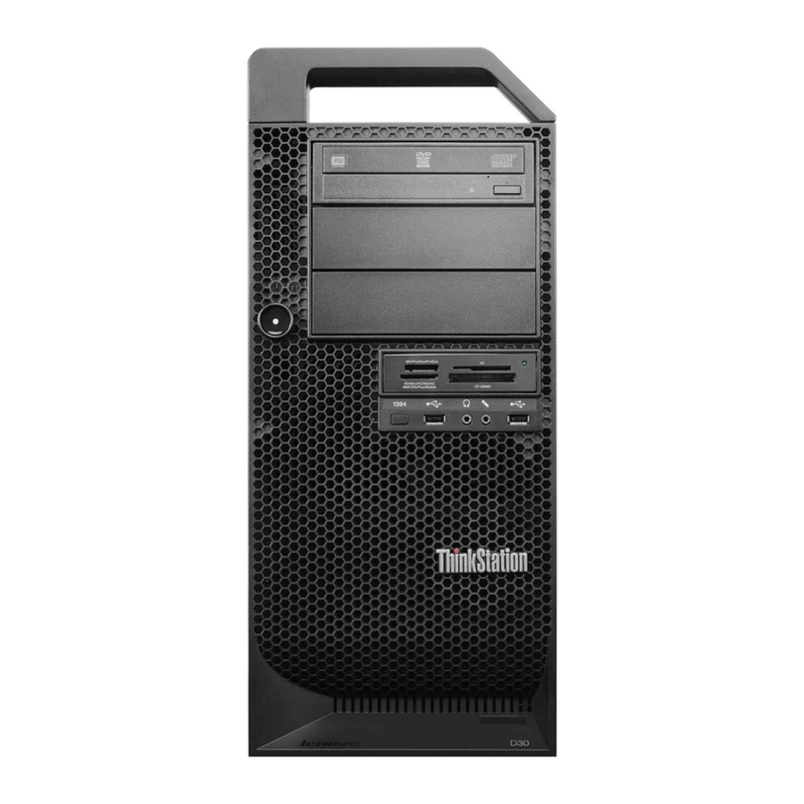
Figure 1. Front connector, control, and indicator locations Optical drive eject/close button 1394 connector (available on some models) USB 2.0 connector Power switch Microphone connector Power indicator Headphone connector Hard disk drive activity indicator USB 2.0 connector © Copyright Lenovo 2012... -
Page 62: Locating Connectors On The Rear Of Your Computer
Locating connectors on the rear of your computer Figure 2 “Rear connector locations” on page 56 shows the locations of the connectors on the rear of your computer. Some connectors on the rear of your computer are color-coded to help you determine where to connect the cables on your computer. - Page 63 Figure 3. Locating major FRUs and CRUs Chapter 9 Locations...
-
Page 64: Looking Up Fru Information
Looking up FRU information For detailed FRU information, such as the FRU part numbers and supported computer models, go to: http:/www.lenovo.com/serviceparts-lookup Locating parts on the system board Figure 4 “System board part locations” on page 59 shows the locations of the parts on the system board. -
Page 65: System Board Part Locations
Figure 4. System board part locations Microprocessor 2 memory slot 3 (DIMM3) ATX power connector Microprocessor 2 memory slot 7 (DIMM7) 12 volt power connector Microprocessor 2 memory slot 4 (DIMM4) SATA port 2 Microprocessor 2 memory slot 8 (DIMM8) SATA port 1 Microprocessor 2 memory cooler connector Hard disk drive connector 5... - Page 66 Clear CMOS (Complementary Metal Oxide PCI Express x16 card slot Semiconductor) / Recovery jumper SATA port 4 PCI Express x4 card slot (x16 mechanical) SATA port 3 Rear fan connector Media card reader connector Microprocessor 2 memory slot 1 (DIMM1) Front panel connector Microprocessor 2 memory slot 5 (DIMM5) Front USB connector...
-
Page 67: Locating Internal Drives
Locating internal drives Internal drives are devices that your computer uses to read and store data. You can add drives to your computer to increase storage capacity and enable your computer to read other types of media. Internal drives are installed in bays. In this manual, the bays are referred to as bay 1, bay 2, and so on. When installing or replacing an internal drive, it is important to note the type and size of the drive that you can install or replace in each bay and correctly connect the cables to the drive installed. - Page 68 ThinkStation Hardware Maintenance Manual...
-
Page 69: Chapter 10. Replacing Frus
Attention: Do not open your computer or attempt any repair before reading and understanding the “Important Safety Information” on page 1. Notes: 1. Use only computer parts provided by Lenovo. 2. When installing or replacing an option, use the appropriate instructions in this section along with the instructions that come with the option. -
Page 70: Removing The Computer Cover
required connector. Then, use the instructions that come with the option to help you make the connection and install any software or device drivers that are required for the option. Removing the computer cover Attention: Do not open your computer or attempt any repair before reading and understanding the “Important Safety Information”... -
Page 71: Removing And Reinstalling The Front Bezel
5. Disengage the cover latch and remove the cover. Place the cover on a flat surface. Figure 6. Removing the computer cover Removing and reinstalling the front bezel Attention: Do not open your computer or attempt any repair before reading and understanding the “Important Safety Information”... -
Page 72: Installing Or Replacing A Pci Card
3. Remove the front bezel by releasing the two plastic tabs on the left side and pivoting the front bezel outward. Figure 7. Removing the front bezel 4. To reinstall the front bezel, align the three plastic tabs on the right side of the front bezel with the corresponding holes in the chassis, and then pivot the front bezel inwards until the two plastic tabs snaps into position on the left side. - Page 73 Figure 8. Opening the PCI card retainer 4. Depending on whether you are installing or replacing a PCI card, do one of the following: • If you are installing a PCI card, remove the appropriate metal card slot cover. • If you are replacing an old PCI card, grasp the old card that is currently installed and gently pull it out of the card slot.
- Page 74 Figure 9. Removing a PCI card Notes: a. The card fits tightly into the card slot. If necessary, alternate moving each side of the card a small amount until it is removed from the card slot. ThinkStation Hardware Maintenance Manual...
-
Page 75: Installing Or Replacing A Memory Module
b. If the card is held in place by a retaining latch, press the card retaining latch as shown to disengage the latch. Grasp the card and gently pull it out of the card slot. 5. Remove the new PCI card from its static-protective package. 6. - Page 76 Turn off the computer and wait three to five minutes to let the computer cool before installing or replacing a memory module. Your computer has 16 slots for installing or replacing DDR3 ECC UDIMMs or DDR3 ECC RDIMMs. When installing or replacing a memory module, use the following guidelines: •...
- Page 77 • If you are replacing an old memory module, open the retaining clips and gently pull the memory module out of the memory slot. Figure 11. Removing a memory module • If you are installing a memory module, open the retaining clips of the memory slot into which you want to install the memory module.
-
Page 78: Installing Or Replacing The Optical Drive
9. Position the new memory module over the memory slot. Make sure that the notch on the memory module aligns correctly with the slot key on the system board. Push the memory module straight down into the slot until the retaining clips close. Figure 13. - Page 79 This section provides instructions on how to install or replace the optical drive. To install or replace an optical drive, do the following: 1. Turn off the computer and disconnect all power cords from electrical outlets. 2. Remove the computer cover. See “Removing the computer cover” on page 64. 3.
- Page 80 6. Install the optical drive retainer on the side of the new optical drive. Figure 16. Installing the optical drive retainer 7. Slide the new optical drive into the drive bay from the front of the computer until the optical drive snaps into position.
-
Page 81: Replacing The Card Reader
8. Connect the signal cable and the power cable to the new optical drive. Figure 18. Connecting the optical drive 9. Reinstall the front bezel. See “Removing and reinstalling the front bezel” on page 65. What to do next: • To work with another piece of hardware, go to the appropriate section. •... - Page 82 6. Press the blue retaining clip to remove the card reader out of the chassis. Figure 19. Removing the card reader 7. Install the card reader retainer on the side of the new card reader. Figure 20. Installing the card reader retainer ThinkStation Hardware Maintenance Manual...
-
Page 83: Replacing The Battery
8. Slide the card reader with retainer into the card reader drive bay until it snaps into position. Figure 21. Installing the card reader 9. Reconnect the card reader cable to the system board. See “Locating parts on the system board” on page 58. -
Page 84: Replacing The Heat Sink And Fan Assembly
Refer to the “Lithium battery notice” in the ThinkStation Safety and Warranty Guide for information about replacing and disposing of the battery. To replace the battery, do the following: 1. Turn off the computer and disconnect all power cords from electrical outlets. 2. - Page 85 CAUTION: The heat sink and fan assembly might be very hot. Turn off the computer and wait three to five minutes to let the computer cool before removing the computer cover. To replace the heat sink and fan assembly, do the following: 1.
-
Page 86: Replacing The Hard Disk Drive Fan Assembly
9. Follow the following sequence to install the four screws to secure each new heat sink and fan assembly. Do not over-tighten the screws. a. Partially tighten screw , then fully tighten screw , and then fully tighten screw b. Partially tighten screw , then fully tighten screw , and then fully tighten screw 10. -
Page 87: Replacing The Rear Fan Assembly
5. Press the tab, and then pivot the hard disk drive fan outward to remove it from the chassis. Figure 25. Removing the hard disk drive fan assembly 6. Position the hard disk drive fan, and then pivot the fan to insert the tab into the chassis. 7. - Page 88 5. The rear fan assembly is attached to the chassis by four rubber mounts. Remove the rear fan assembly by breaking or cutting the rubber mounts and gently pulling the rear fan assembly out of the chassis. Note: The new rear fan assembly will have four new rubber mounts attached. Figure 26.
-
Page 89: Installing Or Replacing A Hard Disk Drive
Figure 27. Installing the rear fan assembly 7. Connect the rear fan assembly cable to the system fan connector on the system board. What to do next: • To work with another piece of hardware, go to the appropriate section. •... - Page 90 2. Remove the computer cover. See “Removing the computer cover” on page 64. 3. Locate the hard disk drive. See “Locating internal drives” on page 61. 4. Disconnect the signal cable and the power cable from the hard disk drive. 5.
- Page 91 7. To install a new hard disk drive into the bracket, flex the bracket and align pin , pin , pin , and on the bracket with the corresponding holes in the hard disk drive. Do not touch the circuit board on the bottom of the hard disk drive.
- Page 92 Figure 31. Installing the hard disk drive 9. Connect the signal cable and the power cable to the new hard disk drive. Note: If you are installing SAS hard disk drives, you must connect the signal cables and power cables to the SAS-to-SATA conversion adapter before you connect them to the hard disk drive.
-
Page 93: Installing Or Replacing A Hard Disk Drive Enablement Module
What to do next: • To work with another piece of hardware, go to the appropriate section. • To complete the installation or replacement, go to “Completing the parts replacement” on page 104. Installing or replacing a hard disk drive enablement module Attention: Do not open your computer or attempt any repair before reading and understanding the “Important Safety Information”... -
Page 94: Replacing The Front Audio And Usb Assembly
7. To install a new hard disk drive enablement module, align the hole in the hard disk drive enablement module with the plastic standoff on the system board, and then position the hard disk drive module over the corresponding connector on the system board. Figure 34. -
Page 95: Replacing The Internal Speaker
5. Disconnect the front audio and USB assembly cables from the system board. See “Locating parts on the system board” on page 58. Note: Make sure you note the locations of the cables when you disconnect the cables from the system board. -
Page 96: Installing Or Replacing The Microprocessor
Note: The internal speaker is only available on some models. To replace the internal speaker, do the following: 1. Turn off the computer and disconnect all power cords from electrical outlets. 2. Remove the computer cover. See “Removing the computer cover” on page 64. 3. - Page 97 1 and the microprocessor socket 2 is protected by a plastic socket cover. You can purchase a microprocessor option kit from Lenovo and install the second microprocessor to expand system capabilities. CAUTION: The heat sink and microprocessor might be very hot.
- Page 98 5. Open the small handle by gently pressing down the small handle, and then pulling the small handle a little bit outward to release it from the secured position. Then, open the other small handle following the same instructions. Ensure that the small handles are in the fully open position. Note: There are two marks on the microprocessor retainer.
- Page 99 • Do not drop anything onto the microprocessor socket while it is exposed. The socket pins must be kept as clean as possible. Figure 39. Removing the microprocessor 8. Touch the static-protective package that contains the new microprocessor to any unpainted surface on the outside of the computer.
- Page 100 10. Note the orientation of the new microprocessor. Hold the new microprocessor by its edges and align the notches on it with the tabs in the microprocessor socket. Then, carefully lower the new microprocessor straight down into the microprocessor socket. Note: The small triangle on one corner of the new microprocessor is the microprocessor orientation indicator.
-
Page 101: Replacing A Microprocessor
1 and the microprocessor socket 2 is protected by a plastic socket cover. You can purchase a microprocessor option kit from Lenovo and install the second microprocessor to expand computer capabilities. CAUTION: The heat sink and microprocessor might be very hot. - Page 102 • Use any documentation that comes with the microprocessor option kit and follow those instructions in addition to the instructions in this topic. • Your microprocessor, socket, and socket cover might look slightly different from the illustrations in this topic. To replace a microprocessor, do the following: 1.
- Page 103 Figure 45. Opening the microprocessor retainer 8. Touch only the edges of the microprocessor and carefully lift it straight up and out of the microprocessor socket. Place the old microprocessor on a static-protective surface. Notes: • Do not touch the gold contacts on the bottom of the microprocessor. •...
- Page 104 10. Remove the new microprocessor from the protective cover that protects the gold contacts on the bottom of the new microprocessor. Do not touch the pins on the microprocessor socket or the gold contacts on the bottom of the new microprocessor. Figure 47.
-
Page 105: Replacing The System Board
12. Pivot the microprocessor retainer downward to close the retainer. Figure 49. Closing the microprocessor retainer 13. Gently press down the small handle , and then push the handle inward to secure it. Then gently press down the small handle and push the handle inward to lock the microprocessor retainer into position and secure the new microprocessor in the socket. - Page 106 CAUTION: The heat sink and microprocessor might be very hot. Turn off the computer and wait three to five minutes to let the computer cool before removing the computer cover. Note: Before replacing the system board, make sure you have a retention module for the new system board. To replace the system board, do the following: 1.
- Page 107 12. Carefully lift the failing system board out of the chassis. 13. Position the new system board into the chassis so that the screw holes in the new system board are aligned with those in the chassis. Install the ten screws that secure the system board to the chassis by following the sequence from 14.
-
Page 108: Replacing The Power Supply Assembly
Figure 53. Securing the microprocessor in the socket 3. Align the notch of the microprocessor socket cover with the alignment key of the microprocessor socket. Lower the socket cover straight down into the microprocessor socket on the system board. Figure 54. Installing the microprocessor socket cover Note: Your microprocessor socket and cover might look slightly different from the illustration. - Page 109 Hazardous voltage, current, and energy levels are present inside any component that has this label attached. There are no serviceable parts inside these components. CAUTION: The heat sink and microprocessor might be very hot. Turn off the computer and wait three to five minutes to let the computer cool before removing the computer cover.
-
Page 110: Completing The Parts Replacement
8. To update your configuration, refer to Chapter 6 “Using the Setup Utility program” on page 37. Note: In most areas of the world, Lenovo requires the return of the defective Customer Replaceable Unit (CRU). Information about this will come with the CRU or will come a few days after the CRU arrives. -
Page 111: Chapter 11. Additional Service Information
• To determine the current Level of BIOS: – Start the Setup Utility program. • Sources for obtaining the latest level BIOS available 1. Lenovo support web site: http://www.lenovo.com/support 2. Lenovo Customer Support Center 3. Levels 1 and 2 Support To update (flash) the BIOS, see “Updating (flashing) the BIOS”... -
Page 112: Updating (Flashing) The Bios From Your Operating System
Updating (flashing) the BIOS from your operating system Note: Because Lenovo makes constant improvements to its Web sites, the Web page contents are subject to change without notice, including the contents referenced in the following procedure. -
Page 113: Power Management
5. Move the jumper from the standard position (pin 1 and pin 2) to the maintenance position (pin 2 and pin 3). 6. Reconnect any cables that were disconnected and reinstall the PCI card if removed. 7. Reinstall the computer cover and reconnect the power cords for the computer and monitor to electrical outlets. - Page 114 Table 2. DIMM type and speed: PC3-10600E DIMM operating voltage Microprocessor model Memory frequency Intel Xeon E5-2603, E5-2609 1066 MHz Intel Xeon E5-2620, E5-2630/2630L, E5-2637, E5-2640, E5-2643, 1.5 V E5-2667, E5-2650/2650L, E5-2660, 1333 MHz E5-2665, E5-2670, E5-2680, E5-2685, E5-2690 Table 3. DIMM type and speed: PC3-10600R DIMM operating voltage Microprocessor model Memory frequency...
-
Page 115: Appendix A. Notices
Lenovo representative for information on the products and services currently available in your area. Any reference to a Lenovo product, program, or service is not intended to state or imply that only that Lenovo product, program, or service may be used. Any functionally equivalent product, program, or service that does not infringe any Lenovo intellectual property right may be used instead. -
Page 116: Television Output Notice
The emission notices information is available in the ThinkStation Safety and Warranty Guide that came with your computer. Trademarks The following terms are trademarks of Lenovo in the United States, other countries, or both: Lenovo The Lenovo logo Rescue and Recovery... -
Page 117: Index
Power-On Password front setting, changing, deleting connectors, controls, indicators passwords front audio and USB assembly, replacing erasing front bezel lost or forgotten front bezel, removing passwords, using front bezel, reinstalling PCI card FRU locations installing, replacing © Copyright Lenovo 2012... - Page 118 slots using physical specifications passwords Power-On, Password Setup Utility rear connectors viewing and changing settings rear fan assembly, replacing recovering from a POST/BIOS update failure recovery boot-block removing computer cover replacing battery 77, 102 card reader hard disk drive hard disk drive enablement module heat sink and fan assembly security enabling or disabling...