Table of Contents
Advertisement
S8225
Version 1.00
Copyright
Copyright © MiTAC Computer Corporation, 2010. All rights reserved. No part of
this manual may be reproduced or translated without prior written consent from
MiTAC Computer Corp.
Trademark
All registered and unregistered trademarks and company names contained in
this manual are property of their respective owners including, but not limited to
the following.
®
TYAN
is a trademark of MiTAC Computer Corporation
®
®
AMD
, Opteron
, and combinations thereof are trademarks of AMD Corporation.
®
®
AMI
, AMIBIOS
and combinations thereof are trademarks of AMI Technologies.
®
®
Microsoft
, Windows
are trademarks of Microsoft Corporation.
®
Aspeed
is a trademark of Aspeed Technology Inc.
Notice
Information contained in this document is furnished by MiTAC Computer
Corporation and has been reviewed for accuracy and reliability prior to printing.
MiTAC assumes no liability whatsoever, and disclaims any express or implied
®
warranty, relating to sale and/or use of TYAN
products including liability or
warranties relating to fitness for a particular purpose or merchantability. MiTAC
retains the right to make changes to product descriptions and/or specifications
at any time, without notice. In no event will MiTAC be held liable for any direct
or indirect, incidental or consequential damage, loss of use, loss of data or other
malady resulting from errors or inaccuracies of information contained in this
document.
Advertisement
Table of Contents

Related Manuals for TYAN S8225


Summary of Contents for TYAN S8225
- Page 1 Corporation and has been reviewed for accuracy and reliability prior to printing. MiTAC assumes no liability whatsoever, and disclaims any express or implied ® warranty, relating to sale and/or use of TYAN products including liability or warranties relating to fitness for a particular purpose or merchantability. MiTAC retains the right to make changes to product descriptions and/or specifications at any time, without notice.
-
Page 2: About This Guide
This chapter tells how to change system settings through the BIOS setup menu. Detailed descriptions of the BIOS parameters are also provided. Chapter4: Diagnostics This chapter introduces some BIOS codes and technical terms to provide better service for the customers. http://www.TYAN.com... -
Page 3: Table Of Contents
3.8 - Boot Menu ....................59 3.9 - Security Menu..................61 3.10 - Chipset Menu ..................63 3.11 - Exit Menu ....................72 Chapter 4: Diagnostics ..............73 4.1 - Beep Codes.....................73 4.2 - Flash Utility....................73 4.3 - AMIBIOS Post Code................74 Glossary..................77 Technical Support ................83 http://www.TYAN.com... -
Page 4: Before You Begin
The retail motherboard package should contain the following: 1x S8225 Motherboard 6x SATA Cable 2x SAS Cable 1xUSB2.0 Cable 2x6 pin Audio Cable IO shielding 1 x S8225 User’s manual 1 x S8225 Quick reference guide ® 1 x TYAN Driver CD http://www.TYAN.com... -
Page 5: Chapter 1: Instruction
S8225 with the power and flexibility to meet demanding requirements for today’s IT environments. The TYAN S8225 series is designed around several different configurations which are detailed in the following 1.2 Hardware Specification section: 1.2 - Hardware Specifications... - Page 6 (2) ports (1 at rear, 1 via cable) (2) Mini-SAS (4-in-1) connectors (1) D-Sub 15-pin VGA port RJ-45 (4) GbE ports ATX12V / Universal 24-pin + 8-pin + 8-pin Power power connectors Front Panel (1) 2x12-pin SSI front panel header http://www.TYAN.com...
- Page 7 - 40° C ~ 70° C (-40° F ~ 158° F) Temp. Environment In/Non-operating 90%, non-condensing at 35° C Humidity RoHS 6/6 RoHS Complaint Motherboard (1) S8225 Motherboard Package Contains Manual (1) User's manual / (1) Quick Ref. Guide Installation CD (1) TYAN installation CD http://www.TYAN.com...
-
Page 8: Software Specifications
TYAN ’s products with FAQs, online manuals and BIOS upgrades and more. 1.3 - Software Specifications ® For OS (operation system) support, please check the TYAN website for the latest information. 1.4 - AST2050 User Guide ®... -
Page 9: Chapter 2: Board Installation
Unplug the power from your computer power supply and then touch a safely grounded object to release static charge (i.e. power ® supply case). For the safest conditions, TYAN recommends wearing a static safety wrist strap. (2) Hold the motherboard by its edges and do not touch the bottom of the board, or flex the board in any way. -
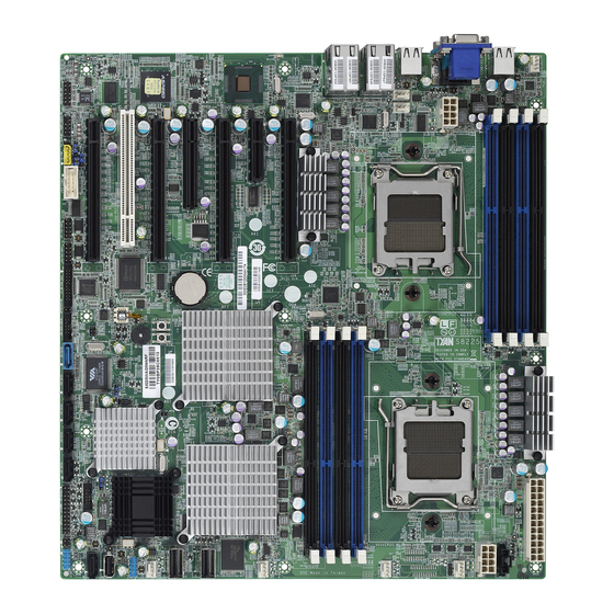
Page 10: Board Image
2.1 - Board Image This diagram is representative of the latest motherboard (S8225WAGM4NRF) revision available at the time of publishing. The board you receive may not look exactly like the above diagram. http://www.TYAN.com... -
Page 11: Block Diagram
2.2 - Block Diagram http://www.TYAN.com... -
Page 12: Board Parts, Jumpers And Connectors
2.3 - Board Parts, Jumpers and Connectors This diagram is representative of the latest board revision (S8225) available at the time of publishing. The board you receive may not look exactly like the above diagram. http://www.TYAN.com... - Page 13 FP Connector CMOS Clear SAS2008 Enable VGA Enable FP Audio Header 1394 Headers 1394 Headers Rear I/O Audio Header SP5100 SATA SGPIO Pin Header Jumper Legend OPEN - Jumper OFF Without jumper cover CLOSED - Jumper ON With jumper cover http://www.TYAN.com...
- Page 14 Jumper Placement J52/J54/J55/J56/J57/J58/J59: 4-Pin FAN Connector ⑴GND/⑵P12V/⑶TACH/⑷PWM Pin1 J71: 20-Pin FAN Connector ⑴TACH1/⑵TACH6/⑶TACH2/⑷TACH7/ ⑸TACH3 ⑹TACH8/⑺TACH4/⑻TACH9/⑼TACH5/ ⑽TACH10/⑾GND/⑿KEY/⒀PWM4/⒁ PWM3/⒂TACH11/⒃NC/⒄TACH12/⒅ NC/⒆NC/⒇PWM5 http://www.TYAN.com...
- Page 15 J26: IPMB Pin Header ⑴ Pin_1 IPMB_SDA/⑵GND/⑶IPMB_SCLK/⑷NC J42: COM2 Pin Header ⑴DCD/⑵DSR/⑶RXD/⑷RTS⑸TXD⑹CTS/ ⑺DTR/⑻RI http://www.TYAN.com...
- Page 16 Put jumper cap back to Pin_1 and Pin_2 (default setting) Use jumper cap to close Pin_2 and Pin_3 Pin_3 Pin_1 for several seconds to Clear CMOS Clear CMOS Reconnect power & power on system http://www.TYAN.com...
- Page 17 J75:SAS2008 Enable Pin_3 Pin_1 ⑴NC/⑵RESET#/⑶GND Pin_3 Pin_1 (1-2: Enable (default) 2-3: Disable) J78:VGA Enable Pin_3 Pin_1 ⑴NC/⑵RESET#/⑶GND Pin_3 Pin_1 (1-2: Enable (default) 2-3: Disable) http://www.TYAN.com...
- Page 18 J85: FP Audio Header(5x2) ⑴MIC2_L/⑵GND/⑶MIC2_R⑷PRESENT#/ ⑸LINEIN2_R/⑹JD/⑺GND/⑻KEY/ ⑼LINEIN2_L/⑽JD J87/J88: 1394 Header ⑴XTPAP/⑵XTPAM/⑶GND/⑷GND/ ⑸XTPBP/⑹XTPBM/⑺Power/⑻Power/⑼Key/ ⑽GND http://www.TYAN.com...
- Page 19 System not identified Note: You can identify the specific system using this LED. Users from remote site could also activate ID LED by input a few commands in IPMI, detailed software http://www.tyan.com for lastest support please visit AST2050 user guide. http://www.TYAN.com...
-
Page 20: Installing The Processor And Heatsink
Your brand new S8225, Only AMD “Opteron™ 4100 series” processors are certified and supported with this motherboard. Check our website for latest processor support. http://www.TYAN.com ® TYAN is not liable for damage as a result of operating an unsupported configuration. - Page 21 The overheated processor is dangerous to the motherboard For the safest method of installation and information on choosing ® the appropriate heat sink, using heat sinks validated by AMD ® Please refer to AMD s website at www.amd.com http://www.TYAN.com...
-
Page 22: Thermal Interface Material
CPU lid (applying too much will actually reduce the cooling). Always check with the manufacturer of the heat sink & processor to ensure the thermal Interface material is compatible with the processor and meets the manufacturer’s warranty requirements. http://www.TYAN.com... -
Page 23: Tips On Installing Motherboard In Chassis
Place 10 screws into the holes indicated by circles to secure the mother board to the chassis. DO NOT overtighten the screws! Doing so can damage the motherboard. http://www.TYAN.com... - Page 24 Some chassis’ include plastic studs instead of metal. Although the plastic ® studs are usable, TYAN recommends using metal studs with screws that will fasten the motherboard more securely in place. Below is a chart detailing what the most common motherboard studs look like and how they should be installed.
-
Page 25: Installing The Memory
All memory must be of the same type and density. Always populate the memory starting from P0_DIMMA1 first. ® Check the TYAN Web site at: www.TYAN.com for details of the type of memory recommended for your motherboard. 1). For the DIMM number please refer to the motherboard placement in “2.3 - Board Parts, Jumpers and... - Page 26 Recommended Memory Population Table ® To achieve the best performance, TYAN strongly recommended memory installation configuration as listed below: Table-1: Per channel populations options for S8225 DIMM0 DIMM1 Max Memory Speed Max Capacity /Channel 1.35V A0/B0 A1/B1 1.5V (6-core only)
- Page 27 • Dual-rank DIMMs are recommended over single-rank DIMMs. • Unbuffered DIMMs can offer slightly better performance than registered DIMMs if populating only a single DIMM per channel. 1). “√”indicates a populated DIMM slot. 2). If installing only one processor, you can choose CPU0. http://www.TYAN.com...
-
Page 28: Memory Installation Procedure
Hold the DIMM by both of its ends . Insert the module vertically into the socket . Apply force to both ends of the DIMM simultaneously until the retaining clip pop up into place. And the DIMM cannot be pushed in any further to ensure proper sitting of the DIMM。 http://www.TYAN.com... -
Page 29: Attaching Drive Cables
If you are in need of SATA/SAS cables or power adapters please contact your place of purchase. The following pictures illustrate how to connect an SATA drive 1. SATA drive cable connection 2. SATA drive power connection 3. SATA cable motherboard connector 4. SATA drive power adapter http://www.TYAN.com... -
Page 30: Installing Add-In Cards
Doing so allows air to circulate within the chassis more easily, thus improving cooling for all installed devices. YOU MUST ALWAYS unplug the power connector to the motherboard before performing system hardware changes to avoid damaging the board or expansion device. http://www.TYAN.com... -
Page 31: Connecting External Devices
10/100/1000 Mbps LAN Link/Activity LED Scheme Left LED Right LED Link Green Amber 10 Mbps Active Blinking Green Green Link Green Amber 100 Mbps Active Blinking Green Green Link Green Amber 1000 Mbps Active Blinking Green Green No Link/10Mb mode(Right) http://www.TYAN.com... -
Page 32: Installing The Power Supply
2.11 - Installing the Power Supply There are two power connectors on your S8225.The S8225 supports 12V power supplies. PWR1: 24-Pin 12V PWR main Connector (Input) +3.3V/⑵+3.3V/⑶GND/⑷+5V/⑸GND ⑴ PIN_1 Good/⑼5VSB/ ⑹+5V/⑺GND⑻PWR ⑽+12V/⑾+12V/⑿+3.3V/⒀+3.3V/⒁ -12V/⒂GND/⒃PS_ON/⒄GND/⒅ GND/⒆GND/⒇Reset/ +5V/ +5V/ (21) (22) +5V/ (23) (24) http://www.TYAN.com... -
Page 33: Finishing Up
We suggest using a 450W per node supply. A 450W is sufficient for most common system configurations, however a higher wattage solution may be needed if the system is fully loaded. Look to the www.TYAN.com website for further information. YOU MUST unplug the power supply before plugging the power cables to motherboard connectors. -
Page 34: Chapter 3: Bios Setup
To configure the advanced chipset features PCI/PnP To configure legacy Plug & Play or PCI settings Boot To configure system boot order Security To configure user and supervisor passwords Chipset To configure chipset management features Exit To exit setup utility http://www.TYAN.com... -
Page 35: Setup Basics
In particular, do not change settings in the Chipset section unless you are absolutely sure of what you are doing. The Chipset defaults have ® been carefully chosen either by TYAN or your system manufacturer for best performance and reliability. Even a seemingly small change to the Chipset setup options may cause the system to become unstable or unusable. -
Page 36: Bios Main Menu
The right frame displays the key legend. Above the key legend is an area reserved for a text message. When an option is selected in the left frame, it is highlighted in white. Often, a text message will accompany it. http://www.TYAN.com... -
Page 37: Bios Advanced Menu
Section for Advanced ACPI Configuration Hardware Health Configuration Configure/monitor the Hardware Health IPMI 2.0 Configuration IPMI configuration including server monitoring and event log Remote Access Configuration Configure Remote Access USB Configuration Configure the USB support Onboard Devices Configuration Configure Onboard Devices http://www.TYAN.com... -
Page 38: Cpu Configuration
[P-state 0] / [P-state 1] / [P-state 2] / [P-state 3] / [P-state 4] ACPI SRAT Table Enable or disable the building of ACPI SRAT Table. [Disabled] / [Enabled] CPU Prefetching Enable or disable CPU prefetching. [Disabled] / [Enabled] http://www.TYAN.com... - Page 39 IO Prefetching Enable or disable IO prefetching. [Disabled] / [Enabled] Probe Filter Initialization mode for Probe Filter. [Auto] / [Disable] / [MP Mode] http://www.TYAN.com...
- Page 40 BIOS. [Disabled] / [Enabled] IDE Detect Time Out (Sec) Select the time out value for detecting ATA/ATAPI device(s). 0~35 (at 5 interval) Select the mechanism for detecting 80Pin ATA(PI) Cable. [Host & Device] / [Host] / [Device] http://www.TYAN.com...
- Page 41 Select Auto to enhance hard disk performance by optimizing the hard disk timing. [Auto]/ 0~4(at 1 interval) DMA Mode Auto: Auto detected [Auto] S. M. A. R. T S. M. A. R. T stands for Self-Monitoring,Analysis and Reporting Technology. [Auto]/[ Disabled]/[ Enabled] 32 Bit Data Transfer Enable/Disable 32-bit Data transfer [Disabled]/[Enable] http://www.TYAN.com...
- Page 42 Allows BIOS to select mode for Serial Port2. [Normal] / [IrDA] / [Ask IR] Parallel Port Address Allows BIOS to select Parallel Port Base Address. [Disabled] / [378] / [278] / [3BC] Parallel Port IRQ Allows BIOS to select Parallel Port IRQ [IRQ7] / [IRQ5] http://www.TYAN.com...
- Page 43 3.7.4 - ACPI Configuration Sub-Menu http://www.TYAN.com...
- Page 44 [Enabled] / [Disabled] OEMB table is used to pass POST data to the AMI code during ACPI O/S operations. Headless Mode Enable or disable Headless operation mode through ACPI. [Disabled] / [Enabled] C1E Support Enhanced C1 state support. [Disabled] / [Enable] http://www.TYAN.com...
- Page 45 3.7.5 - Hardware Health Configuration Sub-Menu Select Smart FAN mode: Select Smart FAN mode [Disabled] / [Enabled] Sensor Data Register Monitoring: Sensor Monitoring for BMC http://www.TYAN.com...
- Page 46 3.7.5.1 - Sensor Data Configuration Sub-Menu Read only. It can not be modified in user mode. http://www.TYAN.com...
- Page 47 Allows the BMC to reset or power down the system if the operating system crashes or hangs. [Disabled] / [Enabled] BMC Alert LED and Beep BMC Alert LED and Beep. [OFF] / [ON] FW Key Enter IPMI FW Key upgrade to IPMI or iKVM function. [0000000] http://www.TYAN.com...
- Page 48 3.7.6.1 View BMC System Event Log Sub-Menu Read only. It can not be modified in user mode. http://www.TYAN.com...
- Page 49 3.7.6.2 LAN Configuration Sub-Menu Read only. It can not be modified in user m http://www.TYAN.com...
- Page 50 IP Address and Subnet Mask appear when IP Address Source is set to [STATIC]. IP Address / Subnet Mask Read only. It can not be modified in user mode. Save LAN Configuration After setup LAN Configuration, select Save LAN Configuration and click [OK] to enable changes. http://www.TYAN.com...
- Page 51 [Alert] / [Power Down] / [Reset System] / [Power Cycle] / [OEM Action] / [Diagnostic. Int]. Alert Startup Delay Enable/disable Alert Startup Delay. [Disabled] / [Enabled] Startup Delay Enable/disable Startup Delay. [Disabled] / [Enabled] Event Message For PEF Action Enable/disable Event Message for PEF Action. [Disabled] / [Enabled] http://www.TYAN.com...
- Page 52 3.7.6.4 Set PEF Configuration Sub-Menu MPS Revision Select MPS Revision. [1.4] / [1.1] http://www.TYAN.com...
- Page 53 Set Maximum Read Request Size of PCI Express Device or allow System BIOS select the value. [Auto] / [Disabled] Active State Power Management Enable/disable PCI Express L0s AND L1 link power states. [Disabled] / [Enabled] Extended Synch If enabled, allows generation of Extended Synchronization patterns. [Auto] / [Disabled] http://www.TYAN.com...
- Page 54 Disabled: Turns off the redirection after POST Boot Loader. Boot Loader: Redirection is active during POST and during Boot Loader. Always: Redirection is always active. (Some Oss may not work if set to Always) [Always] / [Disabled] / [Boot Loader] http://www.TYAN.com...
- Page 55 VT-UTF8 Combo Key Support Enable VT-UFT8 Combination Key Support for ANSI/VT100 terminals. [Enabled] / [Disabled] Sredir Memory Display Delay Gives the delay in seconds to display memory information. [No Delay] / [Delay 1 Sec] / [Delay 2 Sec] / [Delay 4 Sec] http://www.TYAN.com...
- Page 56 This is a work around for OSes without EHCI hand-off support. The EHCI ownership change should claim by EHCI driver. [Enabled] / [Disabled] Legacy USB1.1 HC Support Enables support for legacy USB. Auto option disables legacy support if no USB devices are connected. [Enabled] / [Disabled] http://www.TYAN.com...
- Page 57 This is the default setting and should not be changed unless the VGA card manufacturer requires Palette Snooping to be Enabled. Enabled: informs the PCI devices that an ISA graphics device is installed in the system so the card will function correctly. [Disabled] / [Enabled] http://www.TYAN.com...
- Page 58 Some PCI IDE cards may require this to be set to the PCI slot number that is holding the card. Auto: Works for most PCI IDE cards. [Auto] / [PCI Slot 1] / [PCI Slot 2] / [PCI Slot 3] / [PCI Slot 4]/ [PCI Slot 5] /[PCI Slot 6] http://www.TYAN.com...
-
Page 59: Boot Menu
Select support for PS/2 Mouse. [Auto] / [Enabled] / [Disabled] Wait for ‘F1’ If Error Waits for F1 key to be present if error occurs. [Enabled] / [Disabled] Hit ‘DEL’ Message Display Displays “Press DEL to run Setup in POST”. [Enabled] / [Disabled] http://www.TYAN.com... - Page 60 Interrupt 19 Capture Enabled: allows option ROMs to trap interrupt 19. [Enabled] / [Disabled] http://www.TYAN.com...
-
Page 61: Security Menu
Install or change the password. Boot Sector Virus Protection When it is set to [Enabled], BIOS will issue a virus warning message and beep if a write to the boot sector or the partition table of the HDD is attempted. [Disabled] / [Enabled] http://www.TYAN.com... -
Page 62: Trusted Computing
3.9.1 - Trusted Computing TCG/TPM Support Enable / Disable TPM TCG (TPM 1.1/1.2) support in BIOS. [No] / [Yes] http://www.TYAN.com... -
Page 63: Chipset Menu
3.10 - Chipset Menu Allows you to change NorthBridge, SouthBridge, RD890 and Onboard Peripherals Configuration. http://www.TYAN.com... - Page 64 3.10.1 – NorthBridge Chipset Configuration Sub- Menu Memory Timing Parameters To select which node’s timing parameters to display. [CPU Node 0] / [CPU Node 1] http://www.TYAN.com...
- Page 65 Enable Node Memory Interleaving. [Disabled] / [Enabled] Channel Interleaving Enable Channel Memory Interleaving. [Auto] / [Disabled] CS Sparing Enable Reserve a spare memory rank in each node. [Disabled] / [Enabled] Bank Swizzle Mode Enable or disable bank swizzle mode. [Enabled] / [Disabled] http://www.TYAN.com...
- Page 66 DRAM scrub rate so all of memory is scrubbed in 8 hours. [Basic] / [Super] / [Disabled] / [Good] / [Max] / [User] DRAM ECC Enable DRAM ECC allows hardware to report and correct memory errors automatically maintaining system integrity. [Enabled] / [Disabled] http://www.TYAN.com...
- Page 67 Select the DRAM Frequency programming method. If Auto, the DRAM speed will be based on SPDs. If Limit, the DRAM speed will not exceed the specified value. If Manual, the DRAM speed specified will be programmed by users. [Auto] / [Manual] / [Limit] http://www.TYAN.com...
- Page 68 OHCI HC( Bus 0 Dev 19 Fn 0) USB controller [Disabled]/[Enabled] OHCI HC( Bus 0 Dev 19 Fn 1) USB controller [Disabled]/[Enabled] EHCI HC( Bus 0 Dev 19 Fn 2) USB controller [Disabled]/[Enabled] EHCI HC( Bus 0 Dev 20 Fn 5) USB controller [Disabled]/[Enabled] http://www.TYAN.com...
- Page 69 This one is the AC power sudden power failure shut down the computer. When the electricity came to shut down or when the computer is booting. The setting are off/on/last state. [Power On]/[Power off]/[Last state] MNI Button [Enable]/[Disabled] Chassis intrusion detection [Enable]/[Disabled] http://www.TYAN.com...
- Page 70 PCI GFX-PCIE GFX: Video card scan from PCI bus (onboard VGA) to PCIE bus. [PCIE GFX-PCI GFX] / [PCI GFX-PCIE GFX] Select PCI-E slot1/2 mode Auto: auto detect by BIOS 1x16: Slot1 – x16, Slot2 – not work 2x8: Slot1 – x8, Slot2 – x8 [Auto] / [1x16] / [2x8] http://www.TYAN.com...
- Page 71 Onboard LAN 1/2(82576) [Enabled]/[Disabled] Onboard LAN 1 OPROM [Enabled]/[Disabled] Onboard LAN 2 OPROM [Enabled]/[Disabled] Onboard LAN 3(82574) [Enabled]/[Disabled] Onboard LAN 3 OPROM [Enabled]/[Disabled] Onboard LAN 4 (82574) [Enabled]/[Disabled] Onboard LAN 4 OPROM [Enabled]/[Disabled] Onboard SAS [Enabled]/[Disabled] HD Audio Azalia Device [Enabled]/[Disabled] http://www.TYAN.com...
-
Page 72: Exit Menu
Use this option to load default performance setup values. Use this option when system CMOS values have been corrupted or modified incorrectly. Load Failsafe Defaults Use this option to load all default failsafe setup values. Use this option when troubleshooting. http://www.TYAN.com... -
Page 73: Chapter 4: Diagnostics
Every BIOS file is unique for the motherboard it was designed for. For Flash Utilities, BIOS downloads, and information on how to properly use the Flash ® Utility with your motherboard, please check the TYAN web site: http://www.TYAN.com/ Please be aware that by flashing your BIOS, you agree that in the event of a BIOS flash failure, you must contact your dealer for a ®... -
Page 74: Amibios Post Code
ADM module for initialization. Initialize language and font modules for ADM. Activate ADM module. Initializes the silent boot module. Set the window for displaying text information. Displaying sign-on message, CPU information, setup key message, and any OEM specific information. http://www.TYAN.com... - Page 75 Wait for user input at config display if needed. Uninstall POST INT1Ch vector and INT09h vector. Deinitializes the ADM module. Prepare BBS for Int 19 boot. End of POST initialization of chipset registers. Save system context for ACPI. Passes control to OS Loader (typically INT19h). http://www.TYAN.com...
- Page 76 NOTE http://www.TYAN.com...
-
Page 77: Glossary
The CPU can manipulate data in a buffer before copying it to a disk drive. While this improves system performance (reading to or writing from a disk drive a single time is much faster than doing so repeatedly) there is the possibility of http://www.TYAN.com... - Page 78 CPU. This frees up CPU resources for other tasks. As with IRQs, it is vital that you do not double up devices on a single line. Plug-n-Play devices will take care of this for you. http://www.TYAN.com...
- Page 79 BIOS, it is a ROM chip which can, unlike normal ROM, be updated. This allows you to keep up with changes in the BIOS programs without having to buy a new ® chip. TYAN ’s BIOS updates can be found at http://www.TYAN.com ESCD (Extended System Configuration Data): a format for storing information about Plug-n-Play devices in the system BIOS.
- Page 80 Plug-n-Play require you to reconfigure your system each time you add or change any part of your hardware. PXE (Preboot Execution Environment): one of four components that together make up the Wired for Management 2.0 baseline specification. PXE was http://www.TYAN.com...
- Page 81 SDRAM (Static RAM): unlike DRAM, this type of RAM does not need to be refreshed in order to prevent data loss. Thus, it is faster and more expensive. SLI (Scalable Link Interface): NVIDIA SLI technology links two graphics cards together to provide scalability and increased performance. NVIDIA SLI takes http://www.TYAN.com...
- Page 82 CPUs without damaging the sensitive CPU pins. The CPU is lightly placed in an open ZIF socket, and a lever is pulled down. This shifts the processor over and down, guiding it into the board and locking it into place. http://www.TYAN.com...
-
Page 83: Technical Support
TYAN serves multiple market segments with the industry's most competitive services to support them. "TYAN's tech support is some of the most impressive we've seen, with great response time and exceptional organization in general" ----Anandtech.com Help Resources: 1. - Page 84 Authorization (RMA) number.The RMA number Should be prominently displayed on the outside of the shipping carton and the package should ® be mailed prepaid. TYAN will pay to have the board shipped back to you. Notice for the USA Compliance Information Statement (Declaration of...