
Related Manuals for Electrolux Thermaline 9CHG584126


Summary of Contents for Electrolux Thermaline 9CHG584126
- Page 1 ELECTRIC INDUCTION RANGES FOURNEAUX ÉLECTRIQUES À INDUCTION INSTALLATION- AND OPERATING INSTRUCTIONS INSTRUCTIONS D’INSTALLATION ET D’EMPLOI thermaline S90 Doc. 62.9581.01_UL Edition 1 01.2006 page 3 page 11...
- Page 2 Against wall - contre une paroi Free standing - isolé Connections - Raccordement Gas - Gaz Fig.1 INSTALLATION DRAWINGS - PLANS D'INSTALLATION Doc. 62.9581.01_UL...
- Page 3 Free standing - isolé operated from both sides - ulilisable des deux côtés Connections - Raccordement Gas - Gaz Fig.1 INSTALLATION DRAWINGS - PLANS D'INSTALLATION...
- Page 4 Doc. 62.9581.01_UL...
-
Page 5: Table Of Contents
CONTENTS GENERAL INFORMATION ... 3 INSTALLATION INSTRUCTIONS ... 5 OPERATING INSTRUCTIONS ... 9 SOMMAIRE INSTRUCTIONS GÉNÉRALES ... 11 INSTRUCTIONS RELATIVES À L'INSTALLATION ... 13 OPERATING INSTRUCTIONS ... 17 62.9581.01_UL Page 1... - Page 6 Page 2 62.9581.01_UL...
- Page 7 People with pacemakers should ask their doctor if their health will be endangered near the range. For appliances with a downpipe, the hose should lead into a drain opening which is cov- ered by a grating such that it cannot be kicked or tipped, or a drain gutter should run underneath the appliance.
-
Page 8: General Information
TECHNICAL DATA Voltage Appliance type Appliances inch 9CHG584126 WIWRAFQOOO 9CHG584127 WIXRAFQOOO 19.7 9CHG584128 WIWRAAQOOO 35.4 9CHG584129 WIXRAAQOOO 35.4 9CHG584130 WIWRABQOOO 9CHG584131 WIXRABQOOO 9CHG584132 WIWWAFQQOO 9CHG584133 WIXWAFQQOO 39.4 9CHG584134 WIWWAAQQOO 35.4 9CHG584135 WIXWAAQQOO 35.4 9CHG584136 WIWWABQQOO 9CHG584137 WIXWABQQOO PACKAGING All the packaging materials used are environmentally friendly. They may burnt at an incineration plant or sent for recycling. -
Page 9: Installation Instructions
II . INSTALLATION INSTRUCTIONS INSTALLATION The appliance is designed for connection to fixed lines. The appliances are suitable for setting up as single appliances or as a group of appliances. They can be set up freely in the room, side by side, at the side and/or at the back against a wall. Gaps between two appliances or appliance and sidewall should be filled with a FDA approved silicone such as Samco RTV103. - Page 10 SIDEWALL (D) Fig.2 Assemblage of sidewall The assembly kit contains two of each of the following: hexagonal screws M8x25 (1 / Fig.1), bolts with retaining rings (2 / Fig.1), mounting links (3 / Fig.1), hexagonal screws M8x16 with serrated washers and hexagonal nuts M8, hexagonal screws M5 with serrated washers (4 / Fig.2) and a fastening angle (5 / Fig.2).
- Page 11 FRONT PANELS (A) and (B) Fig.6 Front panel Unscrew screws (1 or 3). Also, in the case of a built-in oven, unscrew screws (2 and/or 4) on the inside of the oven. Pull the panel away forwards and downwards. CONTROL PANEL (C) (3c) Fig.
- Page 12 (B). In order to connect the appliance, the front panel must be removed (see Chapter 2.1 on page 7). Power cable connection as per the electrical diagram. The terminal screws on the range frame are marked as follows: Earth wire Potential equalization...
-
Page 13: Operating Instructions
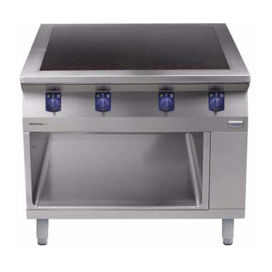
GENERAL The appliance is used for boiling, searing, cooking, keeping warm and preparation. Depending on the type of range, the glass ceramic plate is equipped with two or four rings with an electrical output of 3.5 KW or 5 KW each. -
Page 14: Shutting Down
(e.g. hydrochloric acid). Clean the appliance with commercial cleaning agents. SHUTTING DOWN Never store the range where the temperature can drop below 32 °F (0 °C). Rub all chrome nickel steel surfaces with a cloth soaked in vaseline oil, to lay down a thin protective coating. - Page 15 INSTRUCTIONS GÉNÉRALES CONSIGNES DE SÉCURITÉ ET D'UTILISATION INSTALLATION ET MISE EN SERVICE Le montage, le réglage et la première mise en service de l'appareil doivent s'effectuer confor- mément aux instructions du fabricant et être confiés exclusivement à un technicien agréé. Le raccordement au réseau électrique doit être réalisé...
-
Page 16: Instructions Générales
DONNÉES TECHNIQUES Profondeur Modèle Voltage Appareil PNC de l'appareil inch 9CHG584126 WIWRAFQOOO 9CHG584127 WIXRAFQOOO 19.7 9CHG584128 WIWRAAQOOO 35.4 9CHG584129 WIXRAAQOOO 35.4 9CHG584130 WIWRABQOOO 9CHG584131 WIXRABQOOO 9CHG584132 WIWWAFQQOO 9CHG584133 WIXWAFQQOO 39.4 9CHG584134 WIWWAAQQOO 35.4 9CHG584135 WIXWAAQQOO 35.4 9CHG584136 WIWWABQQOO 9CHG584137 WIXWABQQOO EMBALLAGE Tous les matériaux d'emballage utilisés sont non polluants. -
Page 17: Instructions Relatives À L'installation
INSTRUCTIONS RELATIVES À L'INSTALLATION II . INSTRUCTIONS RELATIVES À L'INSTALLATION MISE EN PLACE Cet appareil est conçu pour être raccordé à des conduites fixes. Les appareils peuvent être montés individuellement ou en groupe. Ils peuvent être installés de façon indépendante, côte à... - Page 18 INSTRUCTIONS RELATIVES À L'INSTALLATION PAROI LATERALE (D) Fig.2 Montage du paroi latérale Chaque kit d'assemblage comprend respectivement deux vis hexagonales M8 x 25 (1 / Fig.1), des boulons avec circlip (2 / Fig.1), des éclisses (3 / Fig.1), des vis hexagonales M8 x 16 avec rondelles à...
- Page 19 INSTRUCTIONS RELATIVES À L'INSTALLATION PANNEAU AVANT (A) et (B) Fig.6 Panneau avant Desserrez les vis (1 et 3 Fig.5, Fig.6). Si le four est encastré, desserrez Extrayez le panneau vers l'avant et le bas. PANNEAU DE COMMANDE (C) (3c) Fig.7 Panneau de commande Enlever l'interrupteur rotatif.
- Page 20 INSTRUCTIONS RELATIVES À L'INSTALLATION BRANCHEMENT ÉLECTRIQUE Chaque appareil est accompagné d'un schéma complet des connexions et du câblage reprenant les données techniques (puissance électrique, tension, intensité de courant, etc.). Il est nécessaire de contrôler que la tension d'alimentation cor- respond aux valeurs indiquées sur la plaque signalétique. Observez ce qui suit : •...
-
Page 21: Operating Instructions
III . OPERATING INSTRUCTIONS GÉNÉRALITÉS L'appareil permet de bouillir, saisir, cuire, tenir au chaud et préparer des aliments. Selon son type, la table de cuisson en vitrocéramique est équipée de deux ou quatre foyers de 3,5 KW ou 5 KW chacun. Chaque zone de cuisson peut être utilisée d'un seul côté... - Page 22 • Si vous avez déposé par mégarde des objets en plastique, des feuilles en aluminium, etc. sur les surfaces vitrocéra- miques chaudes et qu'ils ont fondu, procédez immédiate- ment à leur élimination à l'aide du grattoir spécial. Ne nettoyez jamais l'appareil à l'aide d'un jet d'eau ou d'un appareil de nettoyage sous pression.