Table of Contents
Advertisement
Advertisement
Table of Contents

Related Manuals for Asus P4B266-C


Summary of Contents for Asus P4B266-C
- Page 1 ® P4B266-C User Guide...
- Page 2 Product warranty or service will not be extended if: (1) the product is repaired, modified or altered, unless such repair, modification of alteration is authorized in writing by ASUS; or (2) the serial number of the product is defaced or missing.
-
Page 3: Table Of Contents
How this guide is organized ..........viii Conventions used in this guide ..........ix Where to find more information ..........ix ASUS contact information ..............x Chapter 1: Product introduction ......... 1-1 1.1 Welcome! ................1-1 1.2 Package contents ............... 1-1 1.3 Special features .............. - Page 4 Contents 2.6 Expansion slots ..............2-13 2.6.1 Installing an expansion card ........2-13 2.6.2 Configuring an expansion card ......2-14 2.6.3 PCI slots ............... 2-15 2.6.4 AGP slot ............... 2-15 2.7 Switches and jumpers ............2-16 2.8 Connectors ............... 2-24 Chapter 3: Powering up ............
- Page 5 5.2.3 Software menu ............5-3 5.2.4 Drivers menu ............5-5 5.2.5 DOS Utilities menu ..........5-6 5.2.6 ASUS Contact Information ........5-6 5.2.7 Other information ............ 5-7 5.3 Software information ............5-9 5.3.1 ASUS Update ............5-9 5.3.2 ASUS MyLogo™ ..........5-10 5.3.3...
-
Page 6: Fcc/Cdc Statements
FCC/CDC statements Federal Communications Commission Statement This device complies with FCC Rules Part 15. Operation is subject to the following two conditions: • This device may not cause harmful interference, and • This device must accept any interference received including interference that may cause undesired operation. -
Page 7: Safety Information
Safety information Electrical safety • To prevent electrical shock hazard, disconnect the power cable from the electrical outlet before relocating the system. • When adding or removing devices to or from the system, ensure that the power cables for the devices are unplugged before the signal cables are connected. -
Page 8: About This Guide
About this guide This user guide contains the information you need when installing the ASUS P4B266-C motherboard. How this guide is organized This manual contains the following parts: • Chapter 1: Product introduction This chapter describes the features of the P4B266-C motherboard. It includes brief descriptions of the special attributes of the motherboard and the new technology it supports. -
Page 9: Conventions Used In This Guide
1. ASUS Websites The ASUS websites worldwide provide updated information on ASUS hardware and software products. The ASUS websites are listed in the ASUS Contact Information on page x. 2. Optional Documentation Your product package may include optional documentation, such as warranty flyers, that may have been added by your dealer. -
Page 10: Asus Contact Information
Desktop/Server (Tel): +886-2-2890-7123 (English) Support Fax: +886-2-2890-7698 Support Email: tsd@asus.com.tw Web Site: www.asus.com.tw Newsgroup: cscnews.asus.com.tw ASUS COMPUTER INTERNATIONAL (America) Address: 6737 Mowry Avenue, Mowry Business Center, Building 2, Newark, CA 94560, USA General Fax: +1-510-608-4555 General Email: tmd1@asus.com Technical Support... -
Page 11: Chapter 1: Product Introduction
Chapter 1 This chapter describes the features of the P4B266-C motherboard. It includes brief explanations of the special attributes of the motherboard and the new technology it supports. Product introduction... - Page 12 ASUS P4B266-C motherboard...
-
Page 13: Welcome
Thank you for buying the ASUS P4B266-C motherboard! ® The ASUS P4B266-C motherboard delivers a host of new features and latest technology making it another standout in the long line of ASUS quality motherboards! The P4B266-C incorporates the Intel Pentium 4 Processor in 478-pin ®... -
Page 14: Special Features
Special features 1.3.1 Product highlights Latest processor technology The P4B266-C motherboard supports the latest Intel Pentium 4 478/ ® ® Northwood Processor via a 478-pin surface mount ZIF socket. The Pentium 4 processor utilizes the advanced 0.18 micron processor core in FC-PGA2 package for a 2.0GHz frequency, while the Northwood processor uses the 0.13 micron processor core with 512KB L2 cache for up to a speedy 2.4+GHz frequency. -
Page 15: Value-Added Solutions
ASUS EZ Plug™ This patented ASUS technology lets you use your existing power supply rather than buying a new ATX 12V power supply. The ASUS EZ Plug™ is a 4-pin auxiliary +12V connector mounted on the motherboard to accommodate a regular 4-pin device power connector from the power supply. -
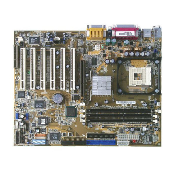
Page 16: Overview
North Bridge controller 22. Parallel port DDR DIMM sockets 23. Game/MIDI port (optional) AGP warning LED 24. Microphone jack (optional) ASUS EZ Plug™ auxiliary +12V 25. Line In jack (optional) connector 26. Line Out jack (optional) ATX power connector 27. Serial ports IDE connectors 28. - Page 17 ASUS P4B266-C motherboard user guide...
- Page 18 AGP slot. When this LED is lit, there is no way you can turn on the system power even if you press the power button. ASUS EZ Plug™ Auxilliary +12V connector. This ASUS patented auxilliary power connector is used if you don’t have an ATX +12V power supply.
- Page 19 (USB) 1.1 interface, and PCI interface. DIP switches. This 10-switch Dual Inline Package (DIP) allows you to set the CPU external frequency. ASUS ASIC. This chip performs multiple system functions that include hardware and system voltage monitoring, IRQ routing, among others.
- Page 20 RJ-45 port. This port allows connection to a Local Area Network (LAN) through a network hub. (on LAN models only) Parallel port. This 25-pin port connects a parallel printer, a scanner, or other devices. Game/MIDI port. This connector supports a joystick or a game pad for playing games, and MIDI devices for playing or editing audio files.
-
Page 21: Chapter 2: Hardware Information
Chapter 2 This chapter describes the hardware setup procedures that you have to perform when installing system components. It includes details on the switches, jumpers, and connectors on the motherboard. Hardware information... - Page 22 ASUS P4B266-C motherboard...
-
Page 23: Motherboard Installation
Place six (6) screws into the holes indicated by circles to secure the motherboard to the chassis. Do not overtighten the screws! Doing so may damage the motherboard. Place this side towards the rear of the chassis ASUS P4B266-C motherboard user guide... -
Page 24: Motherboard Layout
Controller CLR_CMOS (ICH2) PCI2 LINE_IN P4B266-C PCI3 BCS1 Super BCS2 LO_L VPANEL LO_R SWITCH PCI4 AAPANEL 2Mbit Firmware ASUS ASIC PCI5 with Hardware CHASSIS Monitor CR2032 3V Lithium Cell LED1 CMOS Power SMARTCARD MODEM PCI6 AFPANEL SPDIF_C USBPWR23 ® USB11_23... -
Page 25: Before You Proceed
1.5V AGP slot, this LED lights up thus preventing the system to power up. This LED remains off if you plug in a 1.5V AGP card. WARNING Incorrect Correct AGP Card AGP Card LED1 P4B266-C ® Standby Powered Off Power (Power cord unplugged) P4B266-C Onboard LED ASUS P4B266-C motherboard user guide... -
Page 26: Central Processing Unit (Cpu)
Central Processing Unit (CPU) 2.4.1 Overview The motherboard comes with a surface mount 478-pin Zero Insertion Force (ZIF) socket. This socket is specifically designed for the Intel ® Pentium 4 478/Northwood Processor. ® The Intel Pentium 4 Processor in the 478-pin package uses the Flip-Chip Pin Grid Array 2 (FC-PGA2) package technology, and includes the Intel ®... -
Page 27: Installing The Cpu
2. Unlock the socket by pressing the lever sideways, then lift it up to a 90°-100° angle. Socket Lever 90 - 100 Make sure that the socket lever is lifted up to 90°-100° angle, otherwise the CPU does not fit in completely. ASUS P4B266-C motherboard user guide... - Page 28 3. Position the CPU above the socket such that its marked corner matches the base of the socket lever. 4. Carefully insert the CPU into the socket until it fits in place. The CPU fits only in one correct orientation. DO NOT force the CPU into the socket to prevent bending the pins and damaging the CPU! Gold Mark 5.
-
Page 29: Installing The Heatsink And Fan
Your boxed Intel Pentium 4 478/Northwood Processor package should come with installation instructions for the CPU, heatsink, and the retention mechanism. If the instructions in this section do not match the CPU documentation, follow the latter. ASUS P4B266-C motherboard user guide... - Page 30 2. Position the fan with the retention mechanism on top of the heatsink. Align and snap the four hooks of the retention mechanism to the holes on each corner of the module base. Make sure that the fan and retention mechanism assembly perfectly fits the heatsink and module base, otherwise you cannot snap the hooks into the holes.
-
Page 31: Connecting The Cpu Fan Cable
CPU fan cable to the connector on the motherboard labeled CPU_FAN. CPU Fan Connector (CPU_FAN) Don’t forget to connect the CPU fan connector! Hardware monitoring errors may occur if you fail to plug this connector. ASUS P4B266-C motherboard user guide... -
Page 32: System Memory
System memory 2.5.1 Overview The motherboard comes with two Double Data Rate (DDR) Dual Inline Memory Module (DIMM) sockets. These sockets support up to 2GB system memory using unbuffered ECC or non-ECC PC1600/2100 DIMMs. ® 104 Pins P4B266 80 Pins P4B266-C 184-Pin DDR DIMM Sockets A DDR DIMM is keyed with a notch so that it fits in only one direction. -
Page 33: Memory Configurations
1. Unlock a DIMM socket by pressing the retaining clips outward. 2. Align a DIMM on the socket such that the notch on the DIMM matches the break on the socket. Unlocked Retaining Clip ASUS P4B266-C motherboard user guide 2-11... -
Page 34: Removing A Dimm
3. Firmly insert the DIMM into the socket until the retaining clips snap back in place and the DIMM is properly seated. Locked Retaining Clip 2.5.4 Removing a DIMM Follow these steps to remove a DIMM. 1. Simultaneously press the retaining clips outward to unlock the DIMM. Support the DIMM lightly with your fingers when pressing the retaining clips. -
Page 35: Expansion Slots
4. Align the card connector with the slot and press firmly until the card is completely seated on the slot. 5. Secure the card to the chassis with the screw you removed earlier. 6. Replace the system cover. ASUS P4B266-C motherboard user guide 2-13... -
Page 36: Configuring An Expansion Card
2.6.2 Configuring an expansion card After physically installing the expansion card, configure the card by adjusting the software settings. 1. Turn on the system and change the necessary BIOS settings, if any. See Chapter 4 for information on BIOS setup. 2. -
Page 37: Pci Slots
LED is lighted, you cannot turn on the system power even if you press the power button, thus preventing permanent damage to the motherboard. Install only 1.5V AGP cards on this motherboard! P4B266-C Keyed for 1.5v ® P4B266-C Accelerated Graphics Port (AGP) ASUS P4B266-C motherboard user guide 2-15... -
Page 38: Switches And Jumpers
Switches and jumpers The motherboard frequency is adjusted through the DIP switches. The white block represents the switch position. The illustration below shows all the switches in the OFF position. SWITCH 1 2 3 4 5 6 7 8 9 10 1. - Page 39 Make sure that the JEN jumper is set to jumper mode before setting the above switches. The option to set the CPU core:bus frequency multiple is available only on unlocked CPUs. If you are using a locked CPU, setting the switches does not produce any effect. ASUS P4B266-C motherboard user guide 2-17...
- Page 40 3. CPU frequency selection (SWITCH Switches 5-9) This option tells the clock generator what frequency to send the CPU. This allows the selection of the CPU’s external frequency (or Bus Clock). The BUS Clock multiplied by the Frequency Multiple equals the CPU’s internal frequency (the advertised CPU speed).
- Page 41 It is recommended that you keep the default setting (Disable) for system stability. Setting to Stage1 and Stage2 does not guarantee better system performance. DDR_OV DISABLE STAGE1 STAGE2 (Default) P4B266-C ® P4B266-C DDR_OV Setting ASUS P4B266-C motherboard user guide 2-19...
- Page 42 6. USB device wake-up (3-pin USBPWR01, USBPWR23) Set these jumpers to +5V to wake up the computer from S1 sleep mode (CPU stopped, DRAM refreshed, system running in low power mode) using the connected USB devices. Set to +5VSB to wake up from S3 sleep mode (no power to CPU, DRAM in slow refresh, power supply in reduced power mode).
- Page 43 Mic port. Use the audio driver included in the support CD to install the multi- channel audio feature. BCS1 BCS1 BCS2 BCS2 P4B266-C (BASS/CENTER) (CENTER/BASS) (Default) ® P4B266-C Bass Center Setting ASUS P4B266-C motherboard user guide 2-21...
- Page 44 9. Line out selector (2-pin LO_L, LO_R) (on audio models only) By default, these jumpers are shorted (jumper caps on) to route the signal from the audio controller to the rear panel Line Out jack to make it available for audio out devices such as speakers or a headphone. If you connect the Intel Front Panel audio cable to the AAPANEL connector (see page 2-30 for the location), remove the caps from these jumpers to allow automatic switching of audio signal between the...
- Page 45 5. Plug the power cord and turn ON the computer. 6. Hold down the <Del> key during the boot process and enter BIOS setup to re-enter data. Intel I/O Controller (ICH2) P4B266-C CLR_CMOS Short jumper ® to clear CMOS P4B266-C Clear RTC RAM ASUS P4B266-C motherboard user guide 2-23...
-
Page 46: Connectors
Connectors This section describes and illustrates the internal connectors on the motherboard. Some pins are used for connectors or power sources. These are clearly distinguished from jumpers in the Motherboard Layout. Placing jumper caps over these connector pins will cause damage to your motherboard. - Page 47 (usually zigzag) on the IDE ribbon cable to PIN 1. P4B266-C ® P4B266-C IDE Connectors PIN 1 For UltraDMA/100/66 IDE devices, use an 80-conductor IDE cable. The UltraDMA/66 cable included in the motherboard package also supports UltraDMA/100. ASUS P4B266-C motherboard user guide 2-25...
- Page 48 3. Floppy disk drive connector (34-1 pin FLOPPY) This connector supports the provided floppy drive ribbon cable. After connecting one end to the motherboard, connect the other end to the floppy drive. (Pin 5 is removed to prevent incorrect insertion when using ribbon cables with pin 5 plug).
- Page 49 USB port connectors. Connect a 2-port USB connector set to the USB header and mount the USB bracket to an open slot in the chassis. USB11_23 P4B266-C ® P4B266-C USB Header ASUS P4B266-C motherboard user guide 2-27...
- Page 50 CPU. If you are using a standard ATX power supply that does not have the ATX +12V plug, connect one 4-pin device power plug to the ASUS EZ Plug™ connector labeled EZ_PLUG. Make sure that your ATX 12V power supply can provide 8A on the +12V lead and at least 1A on the +5-volt standby lead (+5VSB).
- Page 51 (such as a phone) and a MODEM_OUT (such as a speaker) between the audio and a voice modem card. Ground Ground Left Audio Channel Right Audio Channel AUX (White) CD(Black) P4B266-C MODEM ® P4B266-C Internal Audio Connectors ASUS P4B266-C motherboard user guide 2-29...
- Page 52 10. Internal line in connector (5-pin LINE_IN) (on audio models only) This connector connects to an optional front panel audio module using a 5-pin audio cable. If your chassis has this audio module, you may conveniently connect a microphone on the front panel. By default, pins 1 &...
- Page 53 This connector allows you to connect an optional ASUS iPanel, an easy-to-access drive bay with front I/O ports and status LEDs. If you are not using an ASUS iPanel, you can connect an optional wireless transmitting and receiving infrared module to the SIR connector.
- Page 54 14. Smart Card Reader connector (14-1 pin SMARTCARD) This connector accommodates a Smart Card Reader that allows you to conveniently make transactions such as financial, health care, telephony, or traveling services through a Smart Card user interface software. SMARTCARD P4B266-C ®...
-
Page 55: System Panel Connector
This 2-pin connector allows you to manually place the system into a suspend mode, or “green” mode, where system activity is instantly decreased to save power and to expand the life of certain system components. Attach the case-mounted suspend switch to this 2-pin connector. ASUS P4B266-C motherboard user guide 2-33... - Page 56 • ATX Power Switch / Soft-Off Switch Lead (2-pin PWRBTN) This connector connects a switch that controls the system power. Pressing the power switch turns the system between ON and SLEEP, or ON and SOFT OFF, depending on the BIOS or OS settings. Pressing the power switch while in the ON mode for more than 4 seconds turns the system OFF.
-
Page 57: Chapter 3: Powering Up
Chapter 3 This chapter describes the power up sequence and gives information on the BIOS beep codes. Powering up... - Page 58 ASUS P4B266-C motherboard...
-
Page 59: Starting Up For The First Time
You will not hear the BIOS beeps if you did not connect the case- mounted speaker to the system warning speaker lead. 7. At power on, hold down <Delete> to enter BIOS Setup. Follow the instructions in Chapter 4. ASUS P4B266-C motherboard user guide... -
Page 60: Powering Off The Computer
Powering off the computer You must first exit the operating system and shut down the system before switching off the power. For ATX power supplies, you can press the ATX power switch after exiting or shutting down the operating system. If you use Windows 95/98/2000/XP, click the Start button, click Shut Down, then click the OK button to shut down the computer. -
Page 61: Chapter 4: Bios Setup
Chapter 4 This chapter tells how to change system settings through the BIOS Setup menus. Detailed descriptions of the BIOS parameters are also provided. BIOS setup... - Page 62 ASUS P4B266-C motherboard...
-
Page 63: Managing And Updating Your Bios
4. In DOS mode, type A:\AFLASH <Enter> to run AFLASH. If the word “unknown” appears after Flash Memory:, the memory chip is either not programmable or is not supported by the ACPI BIOS and therefore, cannot be programmed by the Flash Memory Writer utility. ASUS P4B266-C motherboard user guide... - Page 64 5. Select 1. Save Current BIOS to File from the Main menu and press <Enter>. The Save Current BIOS To File screen appears. 6. Type a filename and the path, for example, A:\XXX-XX.XXX, then press <Enter>. Chapter 4: BIOS Setup...
-
Page 65: Updating Bios Procedures
BIOS revision will solve your problems. Careless updating may result to more problems with the motherboard! 1. Download an updated ASUS BIOS file from the Internet (WWW or FTP) (see ASUS CONTACT INFORMATION on page x for details) and save to the boot floppy disk you created earlier. - Page 66 If the Flash Memory Writer utility is not able to successfully update a complete BIOS file, the system may not boot. If this happens, call the ASUS service center for support. Chapter 4: BIOS Setup...
-
Page 67: Bios Setup Program
Because the BIOS software is constantly being updated, the following BIOS setup screens and descriptions are for reference purposes only, and may not exactly match what you see on your screen. ASUS P4B266-C motherboard user guide... -
Page 68: Bios Menu Bar
4.2.1 BIOS menu bar The top of the screen has a menu bar with the following selections: MAIN Use this menu to make changes to the basic system configuration. ADVANCED Use this menu to enable and make changes to the advanced features. -
Page 69: General Help
While moving around through the Setup program, note that explanations appear in the Item Specific Help window located to the right of each menu. This window displays the help text for the currently highlighted field. ASUS P4B266-C motherboard user guide... -
Page 70: Main Menu
Main Menu When you enter the Setup program, the following screen appears. System Time [XX:XX:XX] Sets the system to the time that you specify (usually the current time). The format is hour, minute, second. Valid values for hour, minute and second are Hour: (00 to 23), Minute: (00 to 59), Second: (00 to 59). -
Page 71: Primary And Secondary Master/Slave
Before attempting to configure a hard disk drive, make sure you have the correct configuration information supplied by the drive manufacturer. Incorrect settings may cause the system to fail to recognize the installed hard disk. ASUS P4B266-C motherboard user guide... - Page 72 [User Type HDD] Manually enter the number of cylinders, heads and sectors per track for the drive. Refer to the drive documentation or on the drive label for this information. After entering the IDE hard disk drive information into BIOS, use a disk utility, such as FDISK, to partition and format new IDE hard disk drives.
- Page 73 To make changes to this field, set the Type field to [User Type HDD]. Configuration options: [Disabled] [2 Sectors] [4 Sectors] [8 Sectors] [16 Sectors] [32 Sectors] [Maximum] ASUS P4B266-C motherboard user guide 4-11...
- Page 74 SMART Monitoring [Disabled] This field allows you to enable or disable the S.M.A.R.T. (Self-Monitoring, Analysis and Reporting Technology) system that utilizes internal hard disk drive monitoring technology. This parameter is normally disabled because the resources used in the SMART monitoring feature may decrease system performance.
-
Page 75: Keyboard Features
[6/Sec] [8/Sec] [10/Sec] [12/Sec] [15/Sec] [20/Sec] [24/Sec] [30/Sec] Keyboard Auto-Repeat Delay [1/4 Sec] This field sets the time interval for displaying the first and second characters. Configuration options: [1/4 Sec] [1/2 Sec] [3/4 Sec] [1 Sec] ASUS P4B266-C motherboard user guide 4-13... -
Page 76: Forgot The Password
Main menu items continued... Language [English] This field displays the BIOS language version. Supervisor Password [Disabled] / User Password [Disabled] These fields allow you to set passwords. To set a password, highlight the appropriate field and press <Enter>. Type in a password then press <Enter>. -
Page 77: Advanced Menu
This field determines whether the memory clock frequency is set to be in synchronous or asynchronous mode with respect to the system frequency. The options that appear in the popup menu vary according to the CPU Frequency (MHz). Configuration options: [Auto] [1:1] [3:4] ASUS P4B266-C motherboard user guide 4-15... - Page 78 CPU VCore Setting [Auto] The [Manual] setting allows you to manually select the core voltage supplied to the CPU (see next item). However, it is recommended that you keep the default setting [Auto] to allow the system to automatically determine the appropriate CPU core voltage. CPU VCore [1.750V] (for Willamette) , [1.500V] (for Northwood) When the CPU VCore Setting parameter above is set to [Manual], the CPU VCore item allows you to select a specific CPU core voltage.
- Page 79 OS/2 Onboard Memory > 64M [Disabled] When using OS/2 operating systems with installed DRAM of greater than 64MB, you need to set this option to [Enabled]. Otherwise, leave to the default setting [Disabled]. Configuration options: [Disabled] [Enabled] ASUS P4B266-C motherboard user guide 4-17...
-
Page 80: Chip Configuration
4.4.1 Chip Configuration SDRAM Configuration [By SPD] This parameter allows you to set the optimal timings for items 2–5, depending on the memory modules that you are using. The default setting is [By SPD], which configures items 2–5 by reading the contents in the SPD (Serial Presence Detect) device. - Page 81 [4X Mode] even if you are using an AGP 1X video card. When set to [1X Mode], the AGP interface only provides a peak data throughput of 266MB/s even if you are using an AGP 4x card. Configuration options: [1X Mode] [4X Mode] ASUS P4B266-C motherboard user guide 4-19...
- Page 82 Video Memory Cache Mode [UC] USWC (uncacheable, speculative write combining) is a new cache technology for the video memory of the processor. It can greatly improve the display speed by caching the display data. You must set this to UC (uncacheable) if your display card does not support this feature, otherwise the system may not boot.
-
Page 83: I/O Device Configuration
This field sets the address of the onboard parallel port connector. If you disable this field, the Parallel Port Mode and ECP DMA Select configurations are not available. Configuration options: [Disabled] [378H/ IRQ7] [278H/IRQ5] ASUS P4B266-C motherboard user guide 4-21... - Page 84 Parallel Port Mode [ECP+EPP] This field allows you to set the operation mode of the parallel port. [Normal] allows normal-speed operation but in one direction only; [EPP] allows bidirectional parallel port operation; [ECP] allows the parallel port to operate in bidirectional DMA mode; [ECP+EPP] allows normal speed operation in a two-way mode.
-
Page 85: Pci Configuration
This motherboard supports Universal Serial Bus (USB) devices. Keep the default setting [Enabled] if you want to connect USB devices. Select [Disabled] if you do not wish to use the USB feature. Configuration options: [Disabled] [Enabled] ASUS P4B266-C motherboard user guide 4-23... -
Page 86: Pci Irq Resource Exclusion
Primary VGA BIOS [PCI VGA Card] This field allows you to select the primary graphics card. Configuration options: [PCI VGA Card] [AGP VGA Card] Onboard LAN [Enabled] This field allows you to enable or disable the onboard LAN controller. Keep the default [Enabled] if you wish to use the onboard LAN feature. Set to [Disabled] if you installed a PCI LAN card. -
Page 87: Power Menu
Windows with the APM feature. In Windows 98 or later, APM is automatically installed as indicated by a battery and power cord icon labeled “Power Management” in the Control Panel. Select the item “Advanced” in the Power Management Properties dialog box. ASUS P4B266-C motherboard user guide 4-25... - Page 88 Video Off Option [Suspend -> Off ] This field determines when to activate the video off feature for monitor power management. Configuration options: [Always On] [Suspend -> Off] Video Off Method [DPMS OFF] This field defines the video off features. The Display Power Management System (DPMS) feature allows the BIOS to control the video display card if it supports the DPMS feature.
-
Page 89: Power Up Control
When set to [Enabled], this parameter allows you to turn on the system through a PCI LAN or modem card. This feature requires an ATX power supply that provides at least 1A on the +5VSB lead. Configuration options: [Disabled] [Enabled] ASUS P4B266-C motherboard user guide 4-27... - Page 90 Power Up On USB [Disabled] When set to [Enabled], this item allows you to power up the system through a USB device activity. This feature requires an ATX power supply that provides at least 1A on the +5VSB lead. Configuration options: [Disabled] [Enabled] Power On By PS/2 Keyboard [Space Bar] This parameter allows you to use specific keys on the keyboard to turn on...
-
Page 91: Hardware Monitor
If any of the monitored items is out of range, the following error message appears: “Hardware Monitor found an error. Enter Power setup menu for details”. You will then be prompted to “Press F1 to continue or DEL to enter SETUP”. ASUS P4B266-C motherboard user guide 4-29... -
Page 92: Boot Menu
Boot Menu Boot Sequence The Boot menu allows you to select among the four possible types of boot devices listed using the up and down arrow keys. By using the <+> or <Space> key, you can promote devices and by using the <-> key, you can demote devices. - Page 93 This allows you to enable or disable the full screen logo display feature. Configuration options: [Disabled] [Enabled] Make sure that the above item is set to [Enabled] if you wish to use the ASUS MyLogo™ feature. ASUS P4B266-C motherboard user guide 4-31...
- Page 94 Interrupt Mode [APIC] The Advanced Programmable Interrupt Controller (APIC) setting allows you to distribute interrupt routings other than the 16 IRQs. The Programmable Interrupt Controller (PIC) setting allows you to use the 16 IRQs only. Configuration options: [PIC] [APIC] 4-32 Chapter 4: BIOS Setup...
-
Page 95: Exit Menu
Select this option only if you do not want to save the changes that you made to the Setup program. If you made changes to fields other than system date, system time, and password, the BIOS asks for a confirmation before exiting. ASUS P4B266-C motherboard user guide 4-33... -
Page 96: Discard Changes
Load Setup Defaults This option allows you to load the default values for each of the parameters on the Setup menus. When you select this option or if you press <F5>, a confirmation window appears. Select [Yes] to load default values. -
Page 97: Chapter 5: Software Support
Chapter 5 This chapter describes the contents of the support CD that comes with the motherboard package. Software support... - Page 98 ASUS P4B266-C motherboard...
-
Page 99: Install An Operating System
The contents of the support CD are subject to change at any time without notice. Visit the ASUS website for updates. 5.2.1 Running the support CD To begin using the support CD, simply insert the CD into your CD-ROM drive. -
Page 100: Main Menu
If the welcome screen did not appear automatically, locate and double- click on the file ASSETUP.EXE from the BIN folder in the support CD to display the menus. 5.2.2 Main menu From the welcome screen, the program takes you directly to the main menu. -
Page 101: Software Menu
ASUS Update This program allows you to download the latest version of the BIOS from the ASUS website. Before using the ASUS Update, make sure that you have an Internet connection so you can connect to the ASUS website. Intel LDCM Administrator Setup ®... -
Page 102: Cyberlink Video And Audio Applications
This item installs the PC-cillin 2000 V7.61 anti-virus software. View the PC-cillin online help for detailed information. The above PC-cillin version supports Windows XP operating system and maintains backward compatibility with Windows 95. ASUS Screen Saver This item installs the ASUS screen saver. Chapter 5: Software support... -
Page 103: Drivers Menu
Install the INF Driver before installing the Intel Application Accelerator. This items installs the RealTek PCI Fast Ethernet driver. Audio This item installs the C-Media 6-channel PCi audio driver. Smart Card Reader This items installs the Smart Card Reader device driver. ASUS P4B266-C motherboard user guide... -
Page 104: Dos Utilities Menu
The DOS utilities menu includes items that you can run in DOS mode. These items are also present in the software menu. 5.2.6 ASUS Contact Information Clicking the ASUS Contact Information button displays as stated. You may also find this information on page x of this user guide. Chapter 5: Software support... -
Page 105: Other Information
CD. This section shows the pop-up windows that appear when you click the icons. Motherboard Info The window displays the general specifications of the P4B266-C motherboard. Browse this CD The window displays the support CD contents in graphical format. ASUS P4B266-C motherboard user guide... - Page 106 Technical Support Form The window displays the ASUS Technical Support Request Form that you have to fill up when requesting technical support. Readme The window displays the contents of the support CD and a brief description of each in text format.
-
Page 107: Software Information
This section provides details on the new software applications that the motherboard supports. 5.3.1 ASUS Update The ASUS Update is a utility that allows you to update the motherboard BIOS and drivers. This utility requires an Internet connection either through a network or an Internet Service Provider (ISP). -
Page 108: Asus Mylogo
5.3.2 ASUS MyLogo™ The ASUS MyLogo™ is automatically installed when you install the ASUS Update utility from the software menu. See section “5.2.3 Software menu”. Before using ASUS MyLogo™ feature, use the AFLASH utility to make a copy of your original BIOS file, or obtain the latest BIOS version from the ASUS website. - Page 109 MyLogo directly from the Windows Start menu to change your BIOS boot logo. After you have modified the BIOS file with the new logo, use the ASUS Update utility to upload the new BIOS into the EEPROM. ASUS P4B266-C motherboard user guide...
-
Page 110: Personalized Boot Logo
5.3.3 Personalized Boot Logo Also included in the support CD is a DOS version of ASUS MyLogo™. Locate the application called LOGO.EXE and a sample image library of boot screens in bitmap (BMP) format to install this feature. Back up your system BIOS to a bootable floppy disk before using LOGO.EXE to modify your boot screen. -
Page 111: Multi-Channel Audio Feature
Advanced the Mixer to display the Speaker, Volume, Sound Effects, and Options menus. Make sure that the BCS1/BCS2 jumpers are set correctly before using the 6-channel audio feature. See page 2-21 for the settings. ASUS P4B266-C motherboard user guide 5-13... - Page 112 Running the C-Media Audio Demo Program The C-Media audio demo program allows you to test and fine tune your speaker system. To launch the the multi-channel audio demo program, click on from your desktop, then Start select PCI Audio Applications/ Multi-Channel Audio Demo From the demo program interface, click on...
-
Page 113: Glossary
Glossary This part lists the technical terms that you may encounter when reading this document. - Page 114 ASUS P4B266-C motherboard...
- Page 115 Backup. A copy of a file, directory, or volume on a separate storage device from the original. This copy is for the purpose of data retrieval in case the original is accidentally erased, damaged, or destroyed. ASUS P4B266-C motherboard user guide...
- Page 116 BIOS (Basic Input/Output System). BIOS is a set of routines that control how the computer transfers data between computer components, such as memory, disks, and the display adapter. The BIOS instructions are built into the computer’s read-only memory. BIOS parameters are configurable through the BIOS Setup program.
- Page 117 I/O (Input/Output). The data transfers from the input devices like a keyboard, mouse, or scanner, to the output devices like a printer or the monitor screen. I/O Address. The specific memory location for a particular device. Two devices cannot share the same I/O address space. ASUS P4B266-C motherboard user guide...
- Page 118 IrDA (Infrared Data Association). An internaltional organization that creates and promotes inter-operable, low cost, infrared data interconnection standards that support a walk-up, point-to-point model. The IrDA protocol is designed to support transmission of data between two devices over short-range point-to-point infrared at speeds between 9.6Kbps and 4Mbps.
- Page 119 The Serial Presence Detect function is implemented using a 2048 bit EEPROM component. This nonvolatile storage device contains data programmed by the DIMM manufacturer that identifies the module type and various SDRAM organization and timing parameters. ASUS P4B266-C motherboard user guide...
- Page 120 System Disk. A system disk contains the core file of an operating system and is used to boot up the operating system. TCP/IP (Transmission Control Protocol/Internet Protocol). The communications protocol used by the UNIX system and the Internet. TCP checks for lost packets, puts the data from multiple packets into the correct order, and requests that missing or damaged packets be resent.
-
Page 121: Index
Index This part contains an alphabetical list of the topics found in this document. - Page 122 ASUS P4B266-C motherboard...
- Page 123 Boot Up NumLock Status 4-13 DIMM sockets 1-6 Boot Virus Detection 4-31 DIP switches 1-7, 2-16 Central Processing Unit (CPU) Expansion card fan connector 2-9 installation 2-13 installation 2-5 IRQ assigments 2-14 Level 1/Level 2 Cache 4-16 ASUS P4B266-C motherboard user guide...
- Page 124 Expansion slots 1-7, 2-13 AGP 1-7 Keyboard PCI 1-7 Auto-Repeat Delay 4-13 E-Color 3Deep 5-4 Auto-Repeat Rate 4-13 Features 4-13 Flash EEPROM 1-7 Floppy 3 Mode 4-8 Legacy Diskette 4-8 Hard Disk Drives (HDDs) Motherboard CHS Capacity 4-11 components 1-4 Cylinders 4-11 IRQ Table 2-14 Heads 4-11...
- Page 125 Drivers menu 5-5 Main menu 5-2 motherboard information 5-7 readme file 5-8 Software menu 5-3 Technical Support Form 5-8 Welcome screen 5-1 Winbond Voice Editor 5-13 Suspend Mode 4-26 System Controller North Bridge 1-6 South Bridge 1-6 ASUS P4B266-C motherboard user guide...
- Page 126 Index...