ASROCK Fatal1ty X79 Champion series User Manual
Hide thumbs
Also See for Fatal1ty X79 Champion series:
- Quick installation manual (265 pages) ,
- Quick manual (6 pages) ,
- Installation and configuration manual (11 pages)

Related Manuals for ASROCK Fatal1ty X79 Champion series


Summary of Contents for ASROCK Fatal1ty X79 Champion series
-
Page 1: User Manual
Fatal1ty X79 Champion Series User Manual Version 1.0 Published March 2012 Copyright©2012 ASRock INC. All rights reserved. - Page 2 Fatal1ty Story Who knew that at age 19, I would be a World Champion PC gamer. When I was 13, I actually played competitive billiards in professional tournaments and won four or five games off guys who played at the highest level. I actually thought of making a career of it, but at that young age situations change rapidly.
- Page 3 LIVIN’ LARGE Since my first big tournament wins, I have been a “Professional Cyberathlete”, traveling the world and livin’ large with lots of International media coverage on outlets such as MTV, ESPN and a 60 Minutes segment on CBS to name only a few. It's unreal - it's crazy. I’m living a dream by playing video games for a living.
-
Page 4: Copyright Notice
ASRock. ASRock assumes no responsibility for any errors or omissions that may appear in this manual. With respect to the contents of this manual, ASRock does not provide warranty of any kind, either expressed or implied, including but not limited to the implied warran- ties or conditions of merchantability or fitness for a particular purpose. -
Page 5: Table Of Contents
CrossFireX and Quad CrossFireX Operation Guide 41 2.10 Surround Display Features ..........46 2.11 ASRock Smart Remote Installation Guide ..... 47 2.12 Jumpers Setup ............... 49 2.13 Onboard Headers and Connectors ........ 50 2.14 Smart Switches .............. 58 2.15 Dr. Debug ............... 59 2.16 Post Status Checker ............ - Page 6 3 UEFI SETUP UTILITY ..........70 3.1 Introduction ..............70 3.1.1 UEFI Menu Bar ............ 70 3.1.2 Navigation Keys ........... 71 3.2 Main Screen ..............71 3.3 OC Tweaker Screen ............72 3.4 Advanced Screen ............78 3.4.1 CPU Configuration ..........79 3.4.2 North Bridge Configuration........
-
Page 7: Introduction
In case any modifications of this manual occur, the updated ver- sion will be available on ASRock website without further notice. You may find the latest VGA cards and CPU support lists on ASRock’s website as well. ASRock website http://www.asrock.com... -
Page 8: Specifications
1.2 Specifications Platform - ATX Form Factor: 12.0-in x 10.5-in, 30.5 cm x 26.7 cm - Premium Gold Capacitor design (100% Japan-made high- quality Conductive Polymer Capacitors) ® - Supports Intel Core i7 processor family for the LGA 2011 Socket - Digi Power Design - Advanced 12 + 2 Power Phase Design - Dual-Stack MOSFET (DSM) (see CAUTION 1) - Page 9 - Broadcom BCM57781 - Supports Wake-On-LAN - Supports Energy Efficient Ethernet 802.3az - Supports Dual LAN with Teaming function - Supports PXE Rear Panel I/O I/O Panel - 1 x PS/2 Keyboard Port - 1 x Optical SPDIF Out Port - 1 x Ready-to-Use USB 2.0 Ports - 1 x Fatal1ty Mouse Port (USB 2.0) - 2 x eSATA3 Connectors...
- Page 10 - ASRock OMG (Online Management Guard) (see CAUTION 17) - ASRock Internet Flash (see CAUTION 18) - ASRock HyperDuo Plus Technology (see CAUTION 19) - Hybrid Booster: - CPU Frequency Stepless Control (see CAUTION 20) - ASRock U-COP (see CAUTION 21) - Boot Failure Guard (B.F.G.)
- Page 11 4GB for the reservation for system usage under Windows ® / Vista . For Windows OS with 64-bit CPU, there is no such limitation. ® You can use ASRock XFast RAM to utilize the memory that Windows cannot use.
- Page 12 CPU cores are idle without sacri- ficing computing performance. 10. ASRock Instant Flash is a BIOS flash utility embedded in Flash ROM. This convenient BIOS update tool allows you to update system BIOS ®...
- Page 13 15. ASRock XFast RAM is a new function that is included into F-Stream. It ® fully utilizes the memory space that cannot be used under Windows 32-bit CPU.
- Page 14 enable this function. 19. Get 14 times faster performance! While a SSD and a HDD are connect- ed, HyperDuo Plus makes the SSD become the cache of the HDD and delivers SSD like performance. 20. Although this motherboard offers stepless control, it is not recommended to perform over-clocking.
-
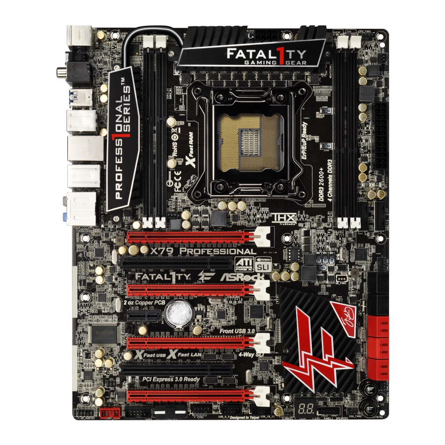
Page 15: Motherboard Layout
1.3 Motherboard Layout 2 x 240-pin DDR3 DIMM Slots Power Switch (PWRBTN1) (DDR3_A1, DDR3_B1, Red) Front Panel IEEE 1394 Header 2 x 240-pin DDR3 DIMM Slots (FRONT_1394, Red) (DDR3_A2, DDR3_B2, Black) Chassis Speaker Header ATX 12V Power Connector (ATX12V1) (SPEAKER1, Black) 2011-Pin CPU Socket Chassis Fan Connector (CHA_FAN2) CPU Fan Connector (CPU_FAN1) -
Page 16: I/O Panel
1.4 I/O Panel Fatal1ty Mouse Port (USB0) Line In (Light Blue) USB 2.0 Port (USB1) ** 11 Front Speaker (Lime) LAN RJ-45 Port Microphone (Pink) IEEE 1394 Port (IEEE 1394) *** 13 eSATA3 Connectors LAN RJ-45 Port USB 3.0 Ports (USB3_56) USB 3.0 Ports (USB3_78) USB 3.0 Ports (USB3_34) Central / Bass (Orange) -
Page 17: Installation
Chapter 2: Installation This is an ATX form factor (12.0" x 10.5", 30.5 x 26.7 cm) motherboard. Before you install the motherboard, study the configuration of your chassis to ensure that the motherboard fits into it. Make sure to unplug the power cord before installing or removing the motherboard. -
Page 18: Cpu Installation
2.3 CPU Installation For the installation of Intel 2011-Pin CPU, please follow the steps below. 2011-Pin Socket Overview Before you insert the 2011-Pin CPU into the socket, please check if the CPU surface is unclean or if there are any bent pins in the socket. Do not force to insert the CPU into the socket if above situation is found. - Page 19 Step 2-2. Locate Pin1 and the two orientation key notches. orientation key notch alignment key Pin1 orientation key notch alignment key 2011-Pin CPU 2011-Pin Socket For proper inserting, please ensure to match the four orientation key notches of the CPU with the four alignment keys of the socket. Step 2-3.
-
Page 20: Installation Of Cpu Fan And Heatsink
2.4 Installation of CPU Fan and Heatsink This motherboard is equipped with a 2011-Pin socket that supports Intel 2011- Pin CPUs. Please adopt the type of heatsink and cooling fan compliant with Intel 2011-Pin CPU to dissipate heat. Before you install the heatsink, you need to spray thermal interface material between the CPU and the heatsink to improve heat dis- sipation. -
Page 21: Installation Of Memory Modules (Dimm)
2.5 Installation of Memory Modules (DIMM) This motherboard provides eight 240-pin DDR3 (Double Data Rate 3) DIMM slots, and supports Quad Channel Memory Technology. For quad channel con- figuration, you always need to install identical (the same brand, speed, size and chip-type) DDR3 DIMM in the slots, so that Quad Channel Memory Tech- nology can be activated. -
Page 22: Installing A Dimm
Installing a DIMM Please make sure to disconnect power supply before adding or removing DIMMs or the system components. Step 1. Unlock the DIMM slot by pressing the retaining clips outward. Step 2. Align the DIMM on the slot such that the notch on the DIMM matches the break on the slot. -
Page 23: Expansion Slots (Pci And Pci Express Slots)
2.6 Expansion Slots (PCI and PCI Express Slots) There are 7 PCI Express slots on this motherboard. PCIE slots:PCIE1 / PCIE3 / PCIE4 / PCIE5 /PCIE7 (PCIE 3.0 x16 slots) are used for PCI Express graphics cards. PCIE2 / PCIE6 (PCIE2.0 x1 slots) are used for PCI Express cards with x1 lane width. -
Page 24: Installing An Expansion Card
Installing an expansion card Step 1. Before installing an expansion card, please make sure that the power supply is switched off or the power cord is unplugged. Please read the documentation of the expansion card and make necessary hardware settings for the card before you start the installation. Step 2. -
Page 25: Asrock Game Blaster Configuration
2.7 ASRock Game Blaster Configuration This section explains how to configure your ASRock Game Blaster. 2.7.1 THX TRUSTUDIO PRO THX TruStudio Pro Click the power button on the left to activate or deactivate. Surround Control the level of audio immersion in music, movies and games. - Page 26 2.7.2 CRYSTALVOICE Select a recording device Mic Volume Control the level of mic volume. Mic Boost Control the level of mic boost. CrystalVoice Click the power button on the left to activate or deactivate. Morph your voice into different characters and accents. Smart Volume Be heard clearly without having to shout or whisper.
- Page 27 2.7.3 SCOUT MODE Scout Mode Enable or disable scout mode. This proprietary technology allows you to hear your enemies from further away, giving you a distinct tactical advantage in combat. Hot Key Configuration Configure hot keys to enable or disable scout mode.
- Page 28 2.7.4 SPEAKERS/HEADPHONES Speakers / Headphones Configuration Select the device connected. If there are both speakers and Optional Speakers: front headphones connected, please select the device you Center desire to use as audio output. Enable or disable center speaker. Subwoofer Enable or disable subwoofer. Rear pair Enable or disable rear pair speakers.
- Page 29 2.7.5 MIXER Playback Speakers Control the level of speakers playback. SPDIF-Out Control the level of SPDIF-Out playback. Balance Control the level of various speaker’s balance. Input Device Select input device. What U Hear Control the level of playback redirect.
- Page 30 2.7.6 EQUALIZER Choose from Flat, Acoustic, Classical, Country, Dance, Jazz, New Age, Pop, Rock and Vocal. 2.7.7 JACK SETUP...
- Page 31 Device Connected: Select the device connected. 5.1 Surround 7.1 EX Surround Stereo and Line-In Show Jack Setup dialog when an audio jack is inserted Enable or disable Jack Setup dialog.
- Page 32 2.7.8 ADVANCED FEATURES Play stereo mix to digital output Enable or disable play stereo mix to digital output.
- Page 33 2.7.9 PROFILE User Profiles You can save, load or delete your user profiles. The default is <Custom>.
- Page 34 Note 1. If you want to hear your own voice through the microphone (Playback mode). You can change your settings to "playback mode" by checking the "Listen to this device" box in Control panel Sound Recording Microphone Properties Listen. 2. If you want to change your playback device to a SPDIF-Out device, go into Control panel Sound Playback, then right click on SPDIF-Out and...
-
Page 35: Sli Tm , 3-Way Sli Tm , 4-Way Sli Tm And Quad Sli Tm
2.8 SLI , 3-Way SLI , 4-Way SLI and Quad SLI Operation Guide ® This motherboard supports NVIDIA , 3-Way SLI , 4-Way SLI and Quad (Scalable Link Interface) technology that allows you to install up to four ® identical PCI Express x16 graphics cards. Currently, NVIDIA technology ®... - Page 36 If required, connect the auxiliary power source to the PCI Express graph- ics cards. Step3. Align and insert the ASRock SLI_Bridge_3S Card to the goldfingers on each graphics card. Make sure the ASRock SLI_Bridge_3S Card is firmly in place. ASRock SLI_Bridge_3S Card Step4.
- Page 37 Repeat this step on the three graphics cards. Step3. Align and insert the ASRock 3-Way SLI Bridge Card to the goldfingers on each graphics card. Make sure the ASRock 3-Way SLI Bridge Card is firmly in place. ASRock 3-Way SLI Bridge Card Step4.
- Page 38 Repeat this step on the other graphics cards. Step3. Align and insert an ASRock SLI Bridge Card to the goldfingers of the first and second graphics card. Install the second ASRock SLI Bridge Card to the goldfingers of the third and fourth graphics card. Connect the second and the fourth graphics card with the ASRock SLI_Bridge_3S Card.
-
Page 39: Driver Installation And Setup
2.8.2 Driver Installation and Setup Install the graphics card drivers to your system. After that, you can enable the Multi- ® Graphics Processing Unit (GPU) feature in the NVIDIA nView system tray utility. Please follow the below procedures to enable the multi-GPU feature. ®... - Page 40 G. Reboot your system. H. You can freely enjoy the benefits of SLI or Quad SLI ® For Windows Vista / Vista 64-bit / 7 / 7 64-bit OS: (For 3-Way SLI or 4-Way SLI mode) A. Follow steps A to E on page 39. B.
-
Page 41: Tm , 4-Way
2.9 CrossFireX , 3-Way CrossFireX , 4-Way CrossFireX Quad CrossFireX Operation Guide This motherboard supports CrossFireX , 3-way CrossFireX , 4-way CrossFireX and Quad CrossFireX . CrossFireX technology offers the most advantageous means available of combining multiple high performance Graphics Processing Units (GPU) in a single PC. - Page 42 Step 2. Connect two Radeon graphics cards by installing a CrossFire Bridge on the CrossFire Bridge Interconnects on the top of the Radeon graphics cards. (The CrossFire Bridge is provided with the graphics card you pur- chase, not bundled with this motherboard. Please refer to your graphics card vendor for details.) CrossFire Bridge Step 3.
-
Page 43: Installing Three Crossfirex Tm -Ready Graphics Cards
2.9.1.2 Installing Three CrossFireX -Ready Graphics Cards ® Step 1. Install identical 3-Way CrossFireX -ready graphics cards that are AMD certified because different types of graphics cards will not work together properly. (Even the GPU chips version shall be the same.) Insert one graphics card into PCIE1 slot, another graphics card to PCIE3 slot, and the other graphics card to PCIE5 slot. - Page 44 2.9.1.3 Installing Four CrossFireX -Ready Graphics Cards ® Step 1. Install identical 4-Way CrossFireX -ready graphics cards that are AMD certified because different types of graphics cards will not work together properly. (Even the GPU chips version shall be the same.) Insert one graphics card into PCIE1 slot, another graphics card into PCIE3 slot, the third graphics card into PCIE5 slot and the last graphics card into PCIE7 slot.
- Page 45 2.9.2 Driver Installation and Setup Step 1. Power on your computer and boot into OS. Step 2. Remove the AMD drivers if you have any VGA drivers installed in your system. The Catalyst Uninstaller is an optional download. We recommend using this utility to uninstall any previously installed Catalyst drivers prior to installation.
-
Page 46: Surround Display Features
Although you have selected the option “Enable CrossFire ”, the CrossFireX function may not work actually. Your computer will automatically reboot. After restarting your computer, please confirm whether the option “Enable CrossFire ” in “AMD Catalyst Control Center” is selected or not; if not, please select it again, and then you are able to enjoy the benefits of CrossFireX Step 7. -
Page 47: Asrock Smart Remote Installation Guide
2.11 ASRock Smart Remote Installation Guide ASRock Smart Remote is only used for ASRock motherboards with a CIR header. Please refer to the procedures below for the quick installation and usage of ASRock Smart Remote. Step1. Find the CIR header located next to the USB 2.0 header on your... - Page 48 The Multi-Angle CIR Receiver does not support Hot-Plug. Please install it before you boot the system. * ASRock Smart Remote is only supported by some ASRock motherboards. Please refer to ASRock's website for the motherboard support list: http://www.asrock.com...
-
Page 49: Jumpers Setup
2.12 Jumpers Setup The illustration shows how jumpers are setup. When the jumper cap is placed on pins, the jumper is “Short”. If no jumper cap is placed on pins, the jumper is “Open”. The illustration shows a 3-pin jumper whose pin1 and pin2 are “Short”... -
Page 50: Onboard Headers And Connectors
2.13 Onboard Headers and Connectors Onboard headers and connectors are NOT jumpers. Do NOT place jumper caps over these headers and connectors. Placing jumper caps over the headers and connectors will cause permanent damage of the motherboard! Serial ATA2 Connectors These four Serial ATA2 (SATA2) connectors support SATA data (SATA2_0_1: see p.15, No. - Page 51 USB 2.0 Headers Besides two default USB 2.0 ports on the I/O panel, there are (9-pin USB_6_7) three USB 2.0 headers on this (see p.15 No. 32) motherboard. Each USB 2.0 header can support two USB 2.0 ports. (9-pin USB_4_5) USB_PWR (see p.15 No.
- Page 52 Consumer Infrared Module Header This header can be used to connect the remote controller (4-pin CIR1) receiver. (see p.15 No. 35) Front Panel Audio Header This is an interface for front panel audio cable that allows (9-pin HD_AUDIO1) convenient connection and (see p.15 No.
- Page 53 RESET (Reset Switch): Connect to the reset switch on the chassis front panel. Press the reset switch to restart the computer if the computer freezes and fails to perform a normal restart. PLED (System Power LED): Connect to the power status indicator on the chassis front panel. The LED is on when the system is operating.
- Page 54 (3-pin CHA_FAN3) CHA_FAN_SPEED (see p.15 No. 12) +12V (3-pin PWR_FAN1) (see p.15 No. 48) +12V PWR_FAN_SPEED CPU Fan Connectors Please connect the CPU fan cable to the connector and (4-pin CPU_FAN1) match the black wire to the (see p.15 No. 5) ground pin.
- Page 55 ATX 12V Power Connector Please connect an ATX 12V power supply to this connector. (8-pin ATX12V1) (see p.15 No. 3) Though this motherboard provides 8-pin ATX 12V power connector, it can still work if you adopt a traditional 4-pin ATX 12V power supply. To use the 4-pin ATX power supply, please plug your power supply along with Pin 1 and Pin 5.
- Page 56 HDMI_SPDIF Header HDMI_SPDIF header, providing SPDIF audio output to HDMI (2-pin HDMI_SPDIF1) VGA card, allows the system to (see p.15 No. 39) connect HDMI Digital TV/ projector/LCD devices. Please connect the HDMI_SPDIF connector of HDMI VGA card to this header. V-Probe Users are able to measure onboard components voltage,...
- Page 57 The Installation Guide of Front USB 3.0 Panel Step 1 Screw the 2.5” HDD/SSD to the Front Step 2 Prepare the bundled Front USB 3.0 Panel, four USB 3.0 Panel with four HDD screws. HDD screws, and six chassis screws. Step 3 Step 4 Screw the Front USB 3.0 Panel to the...
-
Page 58: Smart Switches
2.14 Smart Switches The motherboard has three smart switches: power switch, reset switch and clear CMOS switch, allowing users to quickly turn on/off or reset the system to clear the CMOS values. Power Switch Power Switch is a smart switch, allowing users to quickly turn (PWRBTN) Power... -
Page 59: Dr. Debug
2.15 Dr. Debug Dr. Debug is used to provide code information, which makes troubleshooting even easier. Please see the diagrams below for reading the Dr. Debug codes. Status Code Description 0x00 Not used 0x01 Power on. Reset type detection (soft/hard) 0x02 AP initialization before microcode loading 0x03... - Page 60 0x37 Post-Memory North Bridge initialization is started 0x38 Post-Memory North Bridge initialization (North Bridge module specific) 0x39 Post-Memory North Bridge initialization (North Bridge module specific) 0x3A Post-Memory North Bridge initialization (North Bridge module specific) 0x3B Post-Memory South Bridge initialization is started 0x3C Post-Memory South Bridge initialization (South Bridge module specific) 0x3D...
- Page 61 0x62 Installation of the South Bridge Runtime Services 0x63 CPU DXE initialization is started 0x64 CPU DXE initialization (CPU module specific) 0x65 CPU DXE initialization (CPU module specific) 0x66 CPU DXE initialization (CPU module specific) 0x67 CPU DXE initialization (CPU module specific) 0x68 PCI host bridge initialization 0x69...
-
Page 62: Post Status Checker
0xA6 SCSI Detect 0xA7 SCSI Enable 0xA8 Setup Verifying Password 0xA9 Start of Setup 0xAA Reserved for ASL 0xAB Setup Input Wait 0xAC Reserved for ASL 0xAD Ready To Boot event 0xAE Legacy Boot event 0xAF Exit Boot Services event 0xB0 Runtime Set Virtual Address MAP Begin 0xB1... -
Page 63: Serial Ata (Sata) / Serial Ata2 (Sata2) Hard Disks Installation
2.17 Serial ATA (SATA) / Serial ATA2 (SATA2) Hard Disks Installation ® This motherboard adopts Intel X79 chipset that supports Serial ATA (SATA) / Serial ATA2 (SATA2) hard disks and RAID (RAID 0, RAID 1, RAID 5, RAID 10 and Intel Rapid Storage 3.0) functions. -
Page 64: Hdds
2.19 Hot Plug and Hot Swap for SATA / SATA2 HDDs This motherboard supports Hot Plug and Hot Swap for SATA / SATA2 in RAID / ® AHCI mode. Intel X79 chipset provides hardware support for Advanced Host controller Interface (AHCI), a new programming interface for SATA host controllers developed through a joint industry effort. -
Page 65: Operation Guide
3. Please make sure the SATA / SATA2 / SATA3 driver is installed into system properly. The latest SATA / SATA2 / SATA3 driver is available on our support website: www.asrock.com 4. Make sure to use the SATA power cable & data cable from our motherboard package. - Page 66 How to Hot Plug a SATA / SATA2 / SATA3 HDD: Points of attention, before you process Hot Plug: Please follow the instructions below to process Hot Plug. Improper procedures will cause the SATA / SATA2 / SATA3 HDD damage and data loss. Step 2 Step 1 Please connect the SATA power cable’s...
-
Page 67: Driver Installation Guide
2.22 Driver Installation Guide To install the drivers to your system, please insert the support CD to your optical drive first. Then, the drivers compatible to your system can be auto-detected and listed on the support CD driver page. Please follow the order from top to bottom to install those required drivers. -
Page 68: Installing Windows ® 7 / 7 64-Bit / Vista
® 2.24 Installing Windows 7 / 7 64-bit / Vista / Vista 64-bit Without RAID Functions ® If you want to install Windows 7 / 7 64-bit / Vista / Vista 64-bit OS on your SATA / SATA2 / SATA3 HDDs without RAID functions, please follow the procedures below according to the OS you install. -
Page 69: Untied Overclocking Technology
2.25 Untied Overclocking Technology This motherboard supports Untied Overclocking Technology, which means during overclocking, BCLK enjoys better margin due to fixed PCI / PCIE buses. Before you enable Untied Overclocking function, please enter “Overclock Mode” option of UEFI setup to set the selection from [Auto] to [Manual]. Therefore, BCLK is untied during overclocking, but PCI / PCIE buses are in the fixed mode so that BCLK can operate under a more stable overclocking environment. -
Page 70: Uefi Setup Utility
Chapter 3: UEFI SETUP UTILITY 3.1 Introduction This section explains how to use the UEFI SETUP UTILITY to configure your system. The UEFI chip on the motherboard stores the UEFI SETUP UTILITY. You may run the UEFI SETUP UTILITY when you start up the computer. Please press <F2>... -
Page 71: Navigation Keys
3.1.2 Navigation Keys Please check the following table for the function description of each navigation key. Navigation Key(s) Function Description Moves cursor left or right to select Screens Moves cursor up or down to select items + / - To change option for the selected items <Enter>... -
Page 72: Oc Tweaker Screen
3.3 OC Tweaker Screen In the OC Tweaker screen, you can set up overclocking features. Load CPU EZ OC Setting You can use this option to load CPU EZ overclocking settings. Please note that overclocking may cause damage to your CPU and motherboard. It should be done at your own risk and expense. - Page 73 Turbo Boost Power Limit Use this item to adjust Turbo Boost power limit. Configuration options: [Auto] and [Manual]. The default value is [Auto]. Core Current Limit Use this item to add voltage when CPU is in Turbo mode. Additional Turbo Voltage Use this item to add voltage when CPU is in Turbo mode.
- Page 74 The default is [Auto]. DRAM tRP Use this item to change Row Precharge Time (tRP) Auto/Manual setting. The default is [Auto]. DRAM tRAS Use this item to change RAS# Active Time (tRAS) Auto/Manual setting. The default is [Auto]. DRAM tRFC Use this item to change Refresh Cyle Time (tRFC) Auto/Manual setting.
- Page 75 ODT WR (CH B) Use this item to change ODT WR (CH B) setting. The default is [Auto]. ODT NOM (CH B) Use this item to change ODT NOM (CH B) setting. The default is [Auto]. ODT WR (CH C) Use this item to change ODT WR (CH C) setting.
- Page 76 Use this item to change DRAM tRWDR Auto/Manual setting. The default is [Auto]. DRAM tWWDD Use this item to change DRAM tWWDD Auto/Manual setting. The default is [Auto]. DRAM tWWDR Use this item to change DRAM tWWDR Auto/Manual setting. The default is [Auto].
- Page 77 DRAM Channel A/B CA Use this to select DRAM Chanel A/B CA. The default value is [Auto]. DRAM Channel A/B DQ Use this to select DRAM Chanel A/B DQ. The default value is [Auto]. DRAM Channel C/D CA Use this to select DRAM Chanel C/D CA. The default value is [Auto]. DRAM Channel C/D DQ Use this to select DRAM Chanel C/D DQ.
-
Page 78: Advanced Screen
3.4 Advanced Screen In this section, you may set the configurations for the following items: CPU Configu- ration, North Bridge Configuration, South Bridge Configuration, Storage Configura- tion, Super IO Configuration, ACPI Configuration, USB Configuration and ME Sub- system. Setting wrong values in this section may cause the system to malfunction. -
Page 79: Cpu Configuration
3.4.1 CPU Configuration CPU Ratio Setting Use this item to change the ratio value of this motherboard. Intel Hyper Threading Technology To enable this feature, a computer system with an Intel processor that sup- ports Hyper-Threading technology and an operating system that includes ®... - Page 80 CPU Power Management Configuration Intel SpeedStep Technology Intel SpeedStep technology is Intel’s new power saving technology. Pro- cessors can switch between multiple frequencies and voltage points to en- able power saving. The default value is [Enabled]. Configuration options: ® [Enabled] and [Disabled]. If you install Windows Vista / 7 and want to enable this function, please set this item to [Enabled].
- Page 81 Core Current Limit Use this item to add voltage when CPU is in Turbo mode.
-
Page 82: North Bridge Configuration
3.4.2 North Bridge Configuration PCIE 1 Link Speed This allows you to select PCIE 1 Link Speed. The default value is [GEN3]. PCIE 3 Link Speed This allows you to select PCIE 3 Link Speed. The default value is [GEN3]. PCIE 3 Link Width This allows you to select PCIE 3 Link Width. -
Page 83: South Bridge Configuration
3.4.3 South Bridge Configuration Restore on AC/Power Loss This allows you to set the power state after an unexpected AC/power loss. If [Power Off] is selected, the AC/power remains off when the power recovers. If [Power On] is selected, the AC/power resumes and the system starts to boot up when the power recovers. - Page 84 Onboard Debug Port LED Use this item to enable or disable Onboard Debug Port LED.
-
Page 85: Storage Configuration
3.4.4 Storage Configuration SATA Mode This item is for SATA3_0, SATA3_1 and SATA2_0 to SATA2_3 ports. Use this to select SATA mode. Configuration options: [IDE Mode], [AHCI Mode], [RAID Mode] and [Disabled]. The default value is [AHCI Mode]. AHCI (Advanced Host Controller Interface) supports NCQ and other new features that will improve SATA disk performance but IDE mode does not have these advantages. - Page 86 Marvell 9230 SATA3_M0_M1_M2_M3 Operation Mode This item is for SATA3_M0_M1_M2_M3 ports. Use this to select Marvell SATA3 operation mode. Configuration options: [IDE Mode], [AHCI Mode], and [Disabled]. The default value is [AHCI Mode]. Marvell 9230 RAID Configuration Enter into Marvell Raid Configuration utility.
-
Page 87: Super Io Configuration
3.4.5 Super IO Configuration Serial Port Use this item to enable or disable the onboard serial port. Serial Port Address Use this item to set the address for the onboard serial port. Configuration options: [3F8h / IRQ4] and [3E8h / IRQ4]. Infrared Port Use this item to enable or disable the onboard infrared port. -
Page 88: Acpi Configuration
3.4.6 ACPI Configuration Suspend to RAM Use this item to select whether to auto-detect or disable the Suspend-to- RAM feature. Select [Auto] will enable this feature if the OS supports it. Check Ready Bit Use this item to enable or disable the feature Check Ready Bit. PS/2 Keyboard Power On Use this item to enable or disable PS/2 keyboard to turn on the system from the power-soft-off mode. -
Page 89: Usb Configuration
3.4.7 USB Configuration USB 2.0 Controller Use this item to enable or disable the use of USB 2.0 controller. USB 3.0 Controller Use this item to enable or disable the use of USB 3.0 controller. Legacy USB Support Use this option to select legacy support for USB devices. There are four configuration options: [Enabled], [Auto], [Disabled] and [UEFI Setup Only]. -
Page 90: Me Subsystem
3.4.8 ME Subsystem Intel ME Subsystem Configuration ME Version... -
Page 91: Hardware Health Event Monitoring Screen
3.5 Hardware Health Event Monitoring Screen In this section, it allows you to monitor the status of the hardware on your system, including the parameters of the CPU temperature, motherboard temperature, CPU fan speed, chassis fan speed, and the critical voltage. CPU Fan 1 &... -
Page 92: Boot Screen
3.6 Boot Screen In this section, it will display the available devices on your system for you to config- ure the boot settings and the boot priority. Setup Prompt Timeout This shows the number of seconds to wait for setup activation key. 65535(0XFFFF) means indefinite waiting. -
Page 93: Security Screen
3.7 Security Screen In this section, you may set or change the supervisor/user password for the system. For the user password, you may also clear it. -
Page 94: Exit Screen
3.8 Exit Screen Save Changes and Exit When you select this option, the following message “Save configuration changes and exit setup?” will pop-out. Select [Yes] to save the changes and exit the UEFI SETUP UTILITY. Discard Changes and Exit When you select this option, the following message “Discard changes and exit setup?”... -
Page 95: Software Support
Click on a specific item then follow the installation wizard to install it. 4.2.4 Contact Information If you need to contact ASRock or want to know more about ASRock, welcome to visit ASRock’s website at http://www.asrock.com; or you may contact your... - Page 96 Installing OS on a HDD Larger Than 2TB in AHCI Mode ® This motherboard adopts UEFI BIOS that allows Windows OS to be installed on a large size HDD (>2TB). Please follow the procedures below to install the operating system. ®...
-
Page 97: Installing Os On A Hdd Larger Than 2Tb In Raid Mode
RAID drivers into a USB flash disk. You can download the driver from ASRock's website and unzip the file into a USB flash disk OR copy the file from ASRock motherboard support CD. (please copy the files under the following directory: 32 bit: ..\i386\Win7_Vista_Intel.. - Page 98 E. Please keep the USB flash disk installed until the system's first reboot. ® F. Continue to install OS by following the Windows instructions. ® 5. Follow Windows Installation Guide to install OS. ® If you install Windows 7 64-bit / Vista 64-bit on a large hard disk (ex.
- Page 99 B. Disable “Volume Shadow Copy” service. a. Type “computer management” in the Start Menu, then press “Enter”. b. Go to “Services and Applications>Services”; Then double click “Volume Shadow Copy”.
- Page 100 c. Set “Startup type” to “Disable” then Click “OK”. C. Reboot your system. D. After reboot, please start to install motherboard drivers and utilities. ® Windows 7 64-bit: A. Please request the hotfix KB2505454 through this link: http://support.microsoft.com/kb/2505454/ ® B. After installing Windows 7 64-bit, install the hotfix kb2505454.