Table of Contents
Advertisement
Advertisement
Table of Contents
Troubleshooting

Related Manuals for Actron ABS BrakeScan CP9449


Summary of Contents for Actron ABS BrakeScan CP9449
- Page 1 CP9449 ABS BrakeScan™ User Manual P/N 0002-000-3028...
-
Page 2: Tool Information
Serial Number (Serial No) and Soft- ware Identification (SW ID). If you have questions or concerns Contact Technical Support: Phone: 1-800-228-7667 Website: www.actron.com Copyright Information Copyright © 2007 SPX Corporation All rights reserved. The information, specifications and illustrations in this guide are based on the latest information available at the time of printing. -
Page 3: Table Of Contents
Table of Contents Section 1 – Safety Precautions Read All Instructions ........1-1 Safety Messages . - Page 4 Section 4 – Vehicle Diagnostics ABS Diagnostic Menu ........4-1 Read Codes .
-
Page 5: Section 1 - Safety Precautions
Safety Precautions Section 1 – For your safety, read this manual thoroughly before operating the Tool. Always refer to and follow safety messages and test procedures provided by the manufacturer of the vehicle or equipment being tested. The safety messages presented below and throughout this user’s manual are reminders to the operator to exercise care when using this test instrument. -
Page 6: Icons Used
Safety Precautions Icons Used An icon, when present, gives a graphical description of a potential hazard. Example: Engine systems can malfunction expelling fuel, oil vapors, hot steam, hot toxic exhaust gases, acid, refrigerant and other debris. Safety goggles and protective gloves must be worn by the operator and any bystanders. - Page 7 Safety Precautions • Flammable fuel and vapors can ignite. • Do not smoke, strike a match, or cause a spark in the vicinity of the battery. Battery gases can ignite. • Avoid making an accidental connection between the battery terminals. Do not place anything on the battery. •...
- Page 8 Safety Precautions - If battery acid contacts skin, clothing, or eyes, flush exposed area with water for 10 minutes. Seek medical help. • Do not touch eyes while working near battery. Battery acid can burn eyes and skin. Risk of fire. •...
- Page 9 Safety Precautions Risk of burns. Batteries can produce a short-circuit current • high enough to weld jewelry to metal. - Remove jewelry such as rings, bracelets and watches before working near batteries. Short circuits can cause injury. Risk of burns. •...
- Page 10 Safety Precautions • Do not wear watches, rings, or loose fitting clothing when working in an engine compartment. • Do not place tools or test equipment on fenders or other places in engine compartment. • Barriers are recommended to help identify danger zones in the test area.
- Page 11 Safety Precautions Risk of equipment or circuit damage. • Unless specifically directed by manufacturer, make sure ignition is off before connecting or disconnect- ing connectors or any vehicle electrical terminals. • Do not create a short between battery terminals with a jumper wire or tools.
-
Page 12: Safety Precautions
Safety Precautions 1 – 8 • • • • • • • • • • • • • • • • • • • • • • • • • • • • • • • • • • • • • • • • • • • • • • • • • • • • • • • •... -
Page 13: Section 2 - Getting Started
Section 2 – Getting Started Introduction ABS BrakeScan is the first tool designed for Do-It-Yourselfers to access the ABS diagnostic information. The Tool retrieves codes from the ABS system and provides the definition of each code to help pinpoint the problem areas within the Antilock Brake System that may have caused the ABS light to turn on. -
Page 14: Abs Malfunction Indicator Lamp (Mil)
Getting Started both rear wheels. Under this system, if the left front, right front, or both rear wheels rotate at a speed different from each other, the ABS computer could use up to three separate solenoids to control brake fluid hydraulic pressure. This allowed the ABS system to control the left front, right front, and both rear wheels together independently. -
Page 15: Vehicle Service Information
Getting Started Vehicle Service Information The following is a list of web sites and phone numbers where diagnostic information is available. ✓ Some manuals may be available at your local dealer, auto parts stores, or local public libraries. Domestic Vehicles Web Site Phone Number General Motors... -
Page 16: Data Link Connector (Dlc)
Getting Started Data Link Connector (DLC) The Data Link Connector (DLC) is used with the Tool to communicate with the vehicle’s control module. Data Link Connector Location: ❒ Under dashboard on driver side of vehicle. ❒ If Data Link Connector is not located under the dashboard, a label should be there telling you where it is located. -
Page 17: Section 3 - Using The Tool
Section 3 – Using the Tool The Tool LCD Display - Backlit, 128 x 64 pixel display with contrast adjustment. LEFT/RIGHT and UP/DOWN arrow keys - Moves the cursor to select functions or to select YES or NO. ENTER key - Selects displayed items. BACK key - Goes to the previous screen or level. -
Page 18: Specifications
Using the Tool Specifications Table 1: Specifications Display: 128 x 64 pixel display with contrast adjust Operating Temperature: 0 to 50 C (32 to 122 Storage Temperature: -20 to 70 C (-4 to 158 Internal Power: 9V Battery (not required to read codes) External Power: 7 to 16 Volts ✓... -
Page 19: Display
Using the Tool Display The display has a large viewing area for posting messages, instructions, and diagnostic information. ✓ The back-lit liquid crystal display (LCD) is a 128 x 64 pixel display. ❒ The following symbols may appear on the display. The chart below describes what each symbol means: Indicates that additional information is available on the previous UP arrow key to view the data. -
Page 20: Tool Power Up
Using the Tool Tool Power Up Power for the Tool can come from the vehicle or an internal 9V battery. All functions work when the Tool is connected to the car. The Review Codes, Code Lookup, and System Setup functions will also work on internal battery power. -
Page 21: User Key
Using the Tool User Key The USER key allows you to read codes from the Diagnostic menu without USER key to update or read codes having to select Read Codes. Press the from the vehicle. ❒ USER key is active, the When the icon appears on the display. -
Page 22: Adjust Display Contrast
Using the Tool Adjust Display Contrast System Setup From the menu: SYSTEM SETUP 1. Select Adjust Contrast. UP or DOWN arrow Adjust Contrast • Press the key until Adjust Contrast is high- lighted. • Press ENTER. 2. Adjust Display Contrast. UP arrow key to ADJUST CONTRAST •... -
Page 23: Display Test
Using the Tool Display Test Display Test is used to check the display. ✓ The test turns on every pixel of the display. System Setup From the menu: 1. Select Display Test. UP or DOWN arrow SYSTEM SETUP • Press the Display Test key until is high-... -
Page 24: Keypad Test
Using the Tool Keypad Test Keypad Test is used to verify that SYSTEM SETUP the keys are working correctly. System Setup From the menu: Keypad Test 1. Select Keypad Test. UP or DOWN arrow • Press the Keypad Test key until is high- lighted. -
Page 25: Memory Test
Using the Tool Memory Test Memory Test will test the tool’s internal memory. Run the Memory Test if the Tool: • Has trouble displaying trouble code definitions. • Operates abnormally. System Setup From the menu: SYSTEM SETUP 1. Select Memory Test. ===================== UP or DOWN... -
Page 26: View Tool Information
Using the Tool View Tool Information This function allows you to view specific tool information that may be needed when contacting customer service. From System Setup menu: 1. Select Tool Information. UP or DOWN arrow SYSTEM SETUP • Press the ===================== Tool Information key until... -
Page 27: Connecting The Tool
Using the Tool Connecting the Tool To diagnose a vehicle, connect the Vehicle Diagnostics Cable to the Tool. Tip: If you just want to power up the tool to review codes from the last vehicle tested, then you do not need to attach the Vehicle Diagnostics Cable to the vehicle. -
Page 28: Vehicle Selection
Using the Tool Vehicle Selection Selecting a vehicle is required to communicate with the vehicle and to correctly display DTC definitions. The Tool keeps all data received from the last vehicle selected until a new vehicle is selected or the Tool is reprogrammed to update software. - Page 29 Using the Tool 3. Select to KEEP or ERASE diag- Do You Want to nostic data. Erase Data Stored • To erase data stored from the In the Tool From the Previous previous vehicle test, press Vehicle Tests? LEFT for YES. Then go to Sec- tion 4 for instructions on running Vehicle Diagnostics.
- Page 30 Using the Tool 7. Select the Year. Select Year UP or DOWN arrow • Press the ==================== key to select the Year. 2005 • Press ENTER. 2004 2003 2002 2001 2000 8. Select the Make. Select Make VIN 3 UP or DOWN arrow •...
- Page 31 Using the Tool ✓ When provided, select the exact engine size: ❒ 4.6L ❒ 2.3L ❒ All Others ✓ If a specific engine size is selected, you may also need to select additional information (called Special). If Special information is required to identify the ABS system, go to Step 11 to continue these instructions.
- Page 32 Using the Tool 3 – 16 • • • • • • • • • • • • • • • • • • • • • • • • • • • • • • • • • • • • • • • • • • • • • • • • • • • • • • •...
-
Page 33: Section 4 - Vehicle Diagnostics
Section 4 – Vehicle Diagnostics ABS Diagnostic Menu Diagnostic Menu From the , you can: ❒ Read Codes ❒ DIAGNOSTIC MENU Review Codes ===================== ❒ Lookup Codes Read Codes ❒ Access System Setup Review Codes Code Lookup System Setup 1. Return to the Main Menu. BACK key. -
Page 34: Read Codes
Vehicle Diagnostics Read Codes The Read Codes function allows the Tool to read the diagnostic trouble codes (DTCs) from the vehicle’s control modules. DTCs are used to help determine the cause of a problem or problems with a vehicle. The anti-lock brake control module reports DTCs pertaining to the brake system. - Page 35 Vehicle Diagnostics 2. View diagnostic results and write down the DTCs Four possible results can occur: ❒ If the information returned by the Unexpected Results vehicle does not match the vehicle ===================== selected, you may get an DTCs may be present Unexpected Results message.
-
Page 36: Dtc Examples
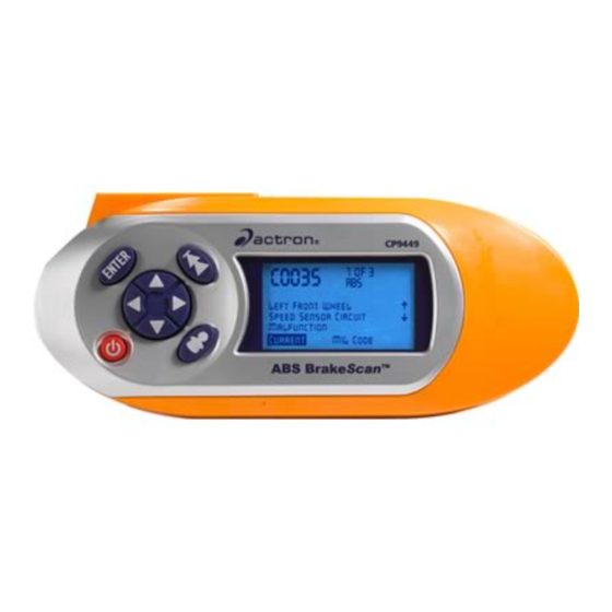
Vehicle Diagnostics DTC Examples Below are several DTC examples. Number of DTCs 1 of 3 C0023 Vehicle Control Module Scroll Up key Left Front Wheel Definition Speed Sensor Circuit User key active Malfunction Scroll Down key DTC Status Current MIL Code MIL Code Status (GM Only) (GM Only) -
Page 37: Code Lookup
Vehicle Diagnostics This code indicates that you have a 3 of 3 U2100 current problem with the Network Bus Communication for the ABS controller Controller Area and that the problem is illuminating the Network Bus ABS malfunction indicator lamp (MIL) Communication on the dashboard. -
Page 38: Review Codes
Vehicle Diagnostics 3. Enter another DTC or exit the function. Code Lookup BACK once then repeat these instructions from Step 2. • Press BACK twice to return to the prior menu. • Press Review Codes The Review Codes function allows the user to view the codes reported from the previous vehicle tested. - Page 39 Vehicle Diagnostics 2. Follow prompts and instructions provided by the Tool. ✓ Refer to “Read Codes” on page 4-2 for a description of the DTC screens. ✓ If data does not exist, a message informs the user to run the Read Code No Data Stored In function.
-
Page 40: Vehicle Diagnostics
Vehicle Diagnostics 4 – 8 • • • • • • • • • • • • • • • • • • • • • • • • • • • • • • • • • • • • • • • • • • • • • • • • • • • • • • • •... -
Page 41: Section 5 - Troubleshooting
Section 5 – Troubleshooting Error Messages Check the following if an error message displays: ❒ Verify ignition key is in the ON and not in the ACCESSORIES position. ❒ Make sure Vehicle Diagnostics Cable is attached to vehicle’s data link connector (DLC) and Tool. -
Page 42: Operating Error Or Erroneous Data
Troubleshooting Operating Error or Erroneous Data An Operating Error or Erroneous Data error occurs if vehicle’s computer(s) stop(s) communicating with Tool. 1. Make Selection. LEFT or RIGHT Operating Error • Press the ===================== arrow key. Operating error • Press ENTER. Check Connections Try Again? ✓... -
Page 43: Tool Self-Tests
• Toll-Free Number: 1-800-228-7667 • Web Address: www.actron.com • • • • • • • • • • • • • • • • • • • • • • • • • • • • • • • • • • • • • • • • • • • • • • • • • • • • • • • • • 5 – 3... -
Page 44: Troubleshooting
Troubleshooting 5 – 4 • • • • • • • • • • • • • • • • • • • • • • • • • • • • • • • • • • • • • • • • • • • • • • • • • • • • • • • •... -
Page 45: Appendix A - Understanding Dtcs
Appendix A – Understanding DTCs Diagnostic Trouble Code (DTC) Formats DTCs are used to help determine the cause of a problem or problems with a vehicle. OBD II Format Codes ❒ OBD II DTCs consist of a five-digit alphanumeric code. ❒... - Page 46 Understanding DTCs Non-OBD II Format Codes ❒ DTCs consist of a 2- or 3-digit alphanumeric code. ❒ The DTCs format and general code types are shown below: 1 of 3 Left Front Wheel Speed Sensor A – 2 • • • • • • • • • • • • • • • • • • • • • • • • • • • • • • • • • • • • • • • • • • • • • • • • • • • • • • • •...
-
Page 47: Appendix B - Glossary
Appendix B – Glossary A/C: Air Conditioner A/D: Analog to Digital A/F: Air/Fuel ratio. The proportion of air and fuel delivered to the cylinder for combustion. For example, an A/F ratio of 14:1 denotes 14 times as much air as fuel in the mixture. - Page 48 Glossary BCM: Body Control Module Boost Control Solenoid: A solenoid that is energized by the PCM, in order to control turbo/supercharger boost pressure. Brake Switch Signal: An input signal to the PCM indicating that the brake pedal is being pressed. This signal is typically used to disengage Cruise Control systems and Torque Converter Clutch (TCC) solenoids.
- Page 49 Glossary CTS: Coolant Temperature Sensor. A resistance sensor that sends a voltage signal to the PCM indicating the temperature of the coolant. This signal tells the PCM whether the engine is cold or warm. CVRTD: Continuous Variable Real Time Damping D/R: Drive/Reverse Data Link Connector (DLC):...
- Page 50 Glossary EFE: Early Fuel Evaporation EFI: Electronic Fuel Injection. Any system where a computer controls fuel delivery to the engine by using fuel injectors. EGR: Exhaust Gas Recirculation. The PCM uses the EGR system to recirculate exhaust gases back into the intake manifold to reduce emissions. EGR is used only during warm engine cruise conditions.
- Page 51 Glossary I/M: Inspection and Maintenance. An emission control program. IAC: Idle Air Control. A device mounted on the throttle body which adjusts the amount of air bypassing a closed throttle so that the PCM can control idle speed. IAT: Intake Air Temperature (Sensor) ICM: Ignition Control Module.
- Page 52 Glossary MAP: Manifold Absolute Pressure (sensor). Measures intake manifold vacuum or pressure and sends a frequency or voltage signal (depending on sensor type) to the PCM. This gives the PCM information on engine load for control of fuel delivery, spark advance, and EGR flow. MAT: Manifold Air Temperature (sensor).
- Page 53 Glossary PCM: Powertrain Control Module. The brains of the engine and transmission control systems housed in a metal box with a number of sensors and actuators connected via a wiring harness. Its job is to control fuel delivery, idle speed, spark advance timing, and emission systems.
- Page 54 Glossary ROM: Read-Only Memory. Permanent programming information stored inside the PCM, containing the information the PCM needs to operate a specific vehicle model/engine combination. RPM: Revolutions Per Minute SAE: Society of Automotive Engineers. Tool: A device that interfaces with and communicates information on a data link. SDM: Sensing and Diagnostic Module Sensor x:...
- Page 55 Glossary TDC: Top Dead Center. When a piston is at its uppermost position in the cylinder. TFP: Transmission Fluid Pressure TFT: Transmission Fluid Temperature (Sensor) Throttle Body: A device which performs the same function as a carburetor in a fuel injection system.
- Page 56 Glossary Warm-up Cycle: Warm-up cycle is when the engine coolant temperature rises at least 40 degrees above that at engine start up. WOT: Wide-Open Throttle. The vehicle operating condition brought about when the throttle is completely (or nearly) open. The PCM typically delivers extra fuel to the engine and de-energizes the A/C compressor at this time for acceleration purposes.
-
Page 57: Spx Corporation Limited Warranty
SPX Corporation Limited Warranty THIS WARRANTY IS EXPRESSLY LIMITED TO ORIGINAL RETAIL BUYERS OF SPX ELECTRONIC DIAGNOSTIC TOOLS (“UNITS”). SPX Units are warranted against defects in materials and workmanship for one year (12 months) from date of delivery. This warranty does not cover any Unit that has been abused, altered, used for a purpose other than that for which it was intended, or used in a manner inconsistent with instructions regarding use. - Page 58 © 2007 SPX Corporation All Rights Reserved. Todos los derechos reservados. Tous droits réservés. P/N 0002-000-3028...