
Related Manuals for eMachines G630


Summary of Contents for eMachines G630
- Page 1 G630/G430 Service Guide Service guide files and updates are available on the ACER/CSD web; for more information, please refer to http://csd.acer.com.tw PRINTED IN TAIWAN...
-
Page 2: Revision History
Revision History Please refer to the table below for the updates made on eMachines G630/G430 service guides. Date Chapter Updates... - Page 3 Copyright Copyright © 2009 by Acer Incorporated. All rights reserved. No part of this publication may be reproduced, transmitted, transcribed, stored in a retrieval system, or translated into any language or computer language, in any form or by any means, electronic, mechanical, magnetic, optical, chemical, manual or otherwise, without the prior written permission of Acer Incorporated.
- Page 4 Conventions The following conventions are used in this manual: Denotes actual messages that appear SCREEN MESSAGES on screen. NOTE Gives bits and pieces of additional information related to the current topic. WARNING Alerts you to any damage that might result from doing or not doing specific actions.
- Page 5 Preface Before using this information and the product it supports, please read the following general information. This Service Guide provides you with all technical information relating to the BASIC CONFIGURATION decided for Acer's "global" product offering. To better fit local market requirements and enhance product competitiveness, your regional office MAY have decided to extend the functionality of a machine (e.g.
-
Page 7: Table Of Contents
G630/G430 BIOS ........ - Page 8 Table of Contents Removing the Right Speaker Module ....... . .64 Removing the TouchPad Bracket .
- Page 9 G630/G430 FRU List ........
- Page 10 Table of Contents...
-
Page 11: System Specifications
Chapter 1 System Specifications Features Below is a brief summary of the computer’s many features: Operating System • Genuine Windows® 7™ Platform • AMD Turion™ II dual-core processor* • AMD Athlon™ 64 II dual-core processor* • AMD Sempron™ processor* • AMD M880G Chipset System Memory •... -
Page 12: Privacy Control
• 3.30 kg (7.29 lbs.) with 6-cell battery pack Communication • Integrated webcam* • WLAN: • 802.11b/g • LAN: • Fast Ethernet; Wake-on-LAN ready Privacy control • BIOS user, supervisor, HDD passwords • Kensington lock slot Power subsystem • ACPI 3.0 •... -
Page 13: System Block Diagram
System Block Diagram Chapter 1... -
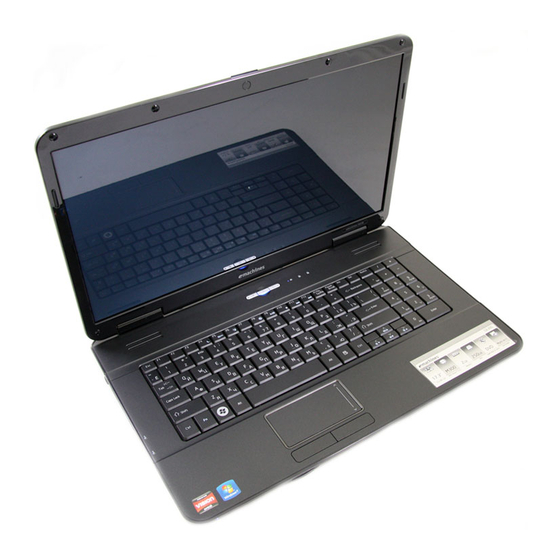
Page 14: Your Acer Notebook Tour
Your Acer Notebook tour Front View Icon Item Description Acer Crystal Eye Web camera for video communication webcam (for selected models). Display screen Also called Liquid-Crystal Display (LCD), displays computer output. Touchpad toggle Turns the internal touchpad on and off. Power button Turns the computer on and off. -
Page 15: Closed Front View
Icon Item Description Click buttons (left The left and right buttons function like the left and right) and right mouse buttons. Palmrest Comfortable support area for your hands when you use the computer. Indicates when the hard disk drive is active. Num Lock Lights up when Num Lock is activated. -
Page 16: Rear View
Rear View Icon Item Description Ventilation slots Enable the computer to stay cool, even after prolonged use. Left View Icon Item Description DC-in jack Connects to an AC adapter Ethernet (RJ-45) Connects to an Ethernet 10/100-based port network. External display Connects to a display device (VGA) port (e.g. -
Page 17: Right View
Right View Item Description Optical drive Internal optical drive; accepts CDs or DVDs. Optical disk access Lights up when the optical drive is active. indicator Optical drive eject button Ejects the optical disk from the drive. Emergency eject hole Ejects the optical drive tray when the computer is turned off. - Page 18 Icon Item Description Hard disk bay Houses the computer's hard disk (secured with screws). Memory Houses the computer's main memory. compartment Ventilation slots Enable the computer to stay cool, even after and cooling fan prolonged use. Note: Do not cover or obstruct the fan opening. Chapter 1...
-
Page 19: Indicators
Indicators The computer has several easy-to-read status indicators. The front panel indicators are visible even when the computer cover is closed. Icon Function Description Power Indicates the computer's power status. Battery Indicates the computer's battery status. Charging: The light shows amber when the battery is charging. -
Page 20: Touchpad Basics
TouchPad Basics The following items show you how to use the TouchPad: • Move your finger across the TouchPad (1) to move the cursor. • Press the left (2) and right (3) buttons located beneath the TouchPad to perform selection and execution functions. -
Page 21: Using The Keyboard
Using the Keyboard The keyboard has full-sized keys and an embedded numeric keypad, separate cursor, lock, Windows, function and special keys. Lock Keys and embedded numeric keypad The keyboard has three lock keys which you can toggle on and off. Lock key Description Caps Lock... -
Page 22: Windows Keys
Windows Keys The keyboard has two keys that perform Windows-specific functions. Description Windows key Pressed alone, this key has the same effect as clicking on the Windows Start button; it launches the Start menu. It can also be used with other keys to provide a variety of functions: <... -
Page 23: Hot Keys
Hot Keys The computer employs hotkeys or key combinations to access most of the computer’s controls like screen brightness, volume output and the BIOS utility. To activate hot keys, press and hold the <Fn> key before pressing the other key in the hotkey combination. Hotkey Icon Function... -
Page 24: Special Key
Special Key You can locate the Euro symbol and the US dollar sign at the upper-center and/or bottom-right of your keyboard. The Euro symbol Open a text editor or word processor. Hold <Alt Gr> and then press the <5> key at the upper-center of the keyboard. NOTE: Note: Some fonts and software do not support the Euro symbol. -
Page 25: Hardware Specifications And Configurations
Hardware Specifications and Configurations Processor Item Specification • AMD Turion™ II dual-core processor • AMD Athlon™ 64 II dual-core processor • AMD Sempron™ processor Core Logic • AMD M880G Chipset • ATI Mobility Radeon™ HD 4570 • ENE KB926 D3 for Keyboard Controller, Battery management Unit, and •... - Page 26 Northbridge Item Specification Chipset AMDRS880M Features HDCP EEPROM Southbridge Item Specification Chipset AMD SB710 Features BIOS Item Specification BIOS vendor Phoenix BIOS BIOS Version V0.11T04 BIOS ROM type Flash Features • Flash ROM 1MB • Supports ISIPP • Supports Acer UI •...
- Page 27 Memory Combinations Slot 1 Slot 2 Total Memory 512MB 512MB 1024MB 1024MB 2048MB 2048MB 512MB 512MB 1024MB 512MB 1024MB 1536MB 512MB 2048MB 2560MB 1024MB 1024MB 1024MB 512MB 1536MB 1024MB 1024MB 2048MB 1024MB 2048MB 3072MB 2048MB 2048MB 2048MB 512MB 2560MB 2048MB 1024MB 3072MB 2048MB...
- Page 28 Item Specification Buffer size 8 MB 8 MB 8 MB Interface SATA SATA SATA SATA Internal transfer 395~952 850 Mbits/s rate (Mbits/sec, (typical) maximum max) I/O data transfer 300 maximum rate (Mbytes/sec max) DC Power Requirements Voltage 5V ±5% 5V ±5% 5V ±5% 5V ±5% tolerance...
- Page 29 Item Specification Applicable disc formats DVD-ROM: DVD Read: • DVD-ROM (DVD-5, DVD-9, DVD-10, DVD-18), 4.7GB (Single Layer) • DVD-Video, DVD-Audio, SACD (Hybrid), 8.5GB (Dual Layer) • UDF DVD, DVD-R, DVD-R DL, DVD-R 3.95 GB, DVD-R: • DVD-R Authoring, DVD-R Multi-Border, 3.95GB (Ver.
- Page 30 Vendor and Model Directivity Current Consumption S/N Ratio Frequency Power and Keyboard Controller Item Specification Controller Keyboard eMACHINES EM-7T Features • Touchpad pointing device Total number of keypads 99-/100-/103-key keyboard Windows logo key Hotkeys See “Hot Keys” on page 13.
-
Page 31: System Utilities
Chapter 2 System Utilities BIOS Setup Utility The BIOS Setup Utility is a hardware configuration program built into your computer’s BIOS (Basic Input/ Output System). Your computer is already properly configured and optimized, and you do not need to run this utility. However, if you encounter configuration problems, you may need to run Setup. -
Page 32: Emachines G630/G430 Bios
G630/G430 BIOS Information The Information screen displays a summary of your computer hardware information. P h o e n i x B I O S S e t u p U t i l i t y Information M a i n... -
Page 33: Main
Main The Main screen allows the user to set the system time and date as well as enable and disable boot option and recovery. P h o e n i x B I O S S e t u p U t i l i t y Information M a i n Security... -
Page 34: Security
Security The Security screen contains parameters that help safeguard and protect your computer from unauthorized use. P h o e n i x B I O S S e t u p U t i l i t y Information M a i n Security B o o t... -
Page 35: Setting A Password
your password. If you forget your password, you may have to return your notebook computer to your dealer to reset it. Setting a Password Follow these steps as you set the user or the supervisor password: Use the ↑ and ↓ keys to highlight the Set Supervisor Password parameter and press the Enter key. The Set Supervisor Password box appears: S e t S u p e r v i s o r P a s s w o r d E n t e r N e w P a s s w o r d... -
Page 36: Changing A Password
Changing a Password Use the ↑ and ↓ keys to highlight the Set Supervisor Password parameter and press the Enter key. The Set Password box appears. S e t S u p e r v i s o r P a s s w o r d E n t e r C u r r e n t P a s s w o r d E n t e r N e w P a s s w o r d C o n f i r m N e w P a s s w o r d... -
Page 37: Boot
Boot This menu allows the user to decide the order of boot devices to load the operating system. Bootable devices includes the USB diskette drives, the onboard hard disk drive and the DVD drive in the module bay. Select Boot Devices to select specific devices to support boot. P h o e n i x B I O S S e t u p U t i l i t y Information M a i n... -
Page 38: Exit
Exit The Exit screen allows you to save or discard any changes you made and quit the BIOS Utility. P h o e n i x B I O S S e t u p U t i l i t y Information M a i n Security... -
Page 39: Bios Flash Utilities
BIOS Flash Utilities The BIOS flash memory update is required for the following conditions: • New versions of system programs • New features or options • Restore a BIOS when it becomes corrupted. Use the Flash utility to update the system BIOS flash ROM. NOTE: If you do not have a crisis recovery diskette at hand, then you should create a Crisis Recovery Diskette before you use the Flash utility. -
Page 40: Dos Flash Utility
DOS Flash Utility Perform the following steps to use the DOS Flash Utility: Press F2 during boot to enter the Setup Menu. Select Boot Menu to modify the boot priority order, for example, if using USB HDD to Update BIOS, move USB HDD to position 1. -
Page 41: Winflash Utility
In flash BIOS, the message Please do not remove AC Power Source displays. Plug in the AC power to continue. Flash is complete when the message Flash programming complete displays. WinFlash Utility Perform the following steps to use the WinFlash Utility: Double-click the WinFlash executable. -
Page 42: Remove Hdd/Bios Password Utilities
Remove HDD/BIOS Password Utilities This section provides you with details about removing HDD/BIOS password: Remove HDD Password: If you key in the wrong HDD password three times, an error is generated. To reset the HDD password, perform the following steps: An error code is generated for unlocking the HDD. - Page 43 Removing BIOS Passwords: To clear the User or Supervisor passwords through hardware, open the WLAN door and use a metal instrument to short the J1 jumper. Cleaning BIOS Passwords To clean the User or Supervisor passwords using software utilites, perform the following steps: From a DOS prompt, execute clnpwd.exe Press 1 or 2 to clean the desired password shown on the screen.
-
Page 44: Using Boot Sequence Selector
The onscreen message determines whether the function is successful or not. Using Boot Sequence Selector The Boot Sequence Selector allows the boot order to be changed without accessing the BIOS. To use Boot Sequence Selector, perform the following steps: Enter into DOS. Execute BS.exe to display the usage screen. -
Page 45: Using Dmitools
Using DMITools The DMI (Desktop Management Interface) Tool copies BIOS information to EEPROM to be used in the DMI pool for hardware management. When the BIOS displays Verifying DMI pool data it is checking that the table correlates with the hardware before sending to the operating system (Windows, etc.). -
Page 46: Using The Lan Mac Eeprom Utility
Using the LAN MAC EEPROM Utility You can use the MAC.BAT utility to write the MAC.CFG file to the EEPROM under DOS mode. Use a text editor (for example: Notepad) to open the MAC.CFG file. You can see the MAC.CFG contents as below: WriteData = ‘001122334455' MAC value... -
Page 47: Machine Disassembly And Replacement
Chapter 3 Machine Disassembly and Replacement IMPORTANT: The outside housing and color may vary from the mass produced model. This chapter contains step-by-step procedures on how to disassemble the notebook computer for maintenance and troubleshooting. Disassembly Requirements To disassemble the computer, you need the following tools: Wrist grounding strap and conductive mat for preventing electrostatic discharge •... -
Page 48: Pre-Disassembly Instructions
Pre-disassembly Instructions Before proceeding with the disassembly procedure, make sure that you do the following: 1. Turn off the power to the system and all peripherals. 2. Unplug the AC adapter and all power and signal cables from the system. 3. -
Page 49: External Module Disassembly Process
External Module Disassembly Process IMPORTANT: The outside housing and color may vary from the mass produced model. External Modules Disassembly Flowchart The flowchart below gives you a graphic representation of the external module disassembly sequence and instructs you on the components that need to be removed during servicing. For example, if you want to remove the keyboard, you must first remove the switch board. -
Page 50: Removing The Battery Pack
Removing the Battery Pack 1. Turn the computer over. Slide the battery lock in the direction shown. 2. Slide and hold the battery release latch to the release position (1), then lift out the battery pack from the main unit (2). Chapter 3... -
Page 51: Removing The Sd Dummy Card
Removing the SD Dummy Card 1. Push the SD dummy card all the way in to eject it. 2. Pull it out from the slot. Chapter 3... -
Page 52: Removing The Lower Covers
Removing the Lower Covers 1. See “Removing the Battery Pack” on page 40. 2. Remove the three (3) screws securing the Memory and HDD Covers. Memory Cover Cover Step Size Quantity Screw Type Lower Covers M2.5*8 3. Remove the HDD cover as shown. 4. -
Page 53: Removing The Optical Drive Module
Removing the Optical Drive Module 1. See “Removing the Battery Pack” on page 40. 2. Remove the screw securing the ODD module. Step Size Quantity Screw Type ODD Module M2.5*8 3. Insert a suitable tool into the access slot in the battery bay as shown. Gently lever the ODD module out of the chassis. - Page 54 5. Remove the two (2) screws securing the ODD bracket and remove the ODD bracket from the optical disk drive module. Step Size Quantity Screw Type ODD Bracket M2*3 6. Remove the ODD bezel by rotating the top edge downward and pulling it clear of the module. Chapter 3...
-
Page 55: Removing The Dimm Modules
Removing the DIMM Modules 1. See “Removing the Lower Covers” on page 42. 2. Push out the release latches on both sides of the DIMM socket to release the DIMM module. 3. Remove the DIMM module. 4. Repeat steps for the second DIMM module if present. Chapter 3... -
Page 56: Removing The Wlan Module
Removing the WLAN Module 1. See “Removing the Lower Covers” on page 42. 2. Remove the adhesive tape securing the Antenna cables in place. 3. Disconnect the antenna cables from the WLAN Board. NOTE: Cable placement is Black to the MAIN terminal (upper) and White to the AUX terminal (lower). Chapter 3... - Page 57 4. Move the antenna away and remove the two (2) screws to release the WLAN Board. Step Size Quantity Screw Type WLAN Module M2*3 5. Detach the WLAN Board from the WLAN socket. NOTE: When reattaching the antennas, ensure the cables are tucked into the chassis to prevent damage. Chapter 3...
-
Page 58: Removing The Hard Disk Drive Module
Removing the Hard Disk Drive Module 1. See “Removing the Lower Covers” on page 42. 2. Using the pull-tab, slide the HDD Module in the direction of the arrow to disconnect the interface. 3. Lift the HDD Module clear of the HDD bay. NOTE: To prevent damage to device, avoid pressing down on it or placing heavy objects on top of it. - Page 59 4. Remove the four (4) screws (two each side) securing the hard disk to the carrier. Step Size Quantity Screw Type HDD Carrier M3*3 5. Remove the HDD from the carrier. Chapter 3...
-
Page 60: Main Unit Disassembly Process
Main Unit Disassembly Process Main Unit Disassembly Flowchart Remove External Remove Remove Modules before Switch Cover Keyboard proceeding Remove LCD Module Remove Upper Cover Upper Lower Cover Cover Remove Remove Remove Remove Left Speaker Right Speaker TouchPad Power Board Module Module Bracket Remove... -
Page 61: Removing The Switch Cover
Removing the Switch Cover CAUTION: Using metal tools to remove the Switch Cover may cause damage to the outer casing. The use of plastic tools or fingers is recommended to remove the Switch Cover. 1. See “Removing the Battery Pack” on page 40. 2. -
Page 62: Removing The Keyboard
Removing the Keyboard 1. See “Removing the Switch Cover” on page 51. 2. Pry up the centre of the Keyboard and rotate it upward away from the Upper Cover. 3. Turn the keyboard over on to the TouchPad area to expose the FFC connector. 4. -
Page 63: Removing The Lcd Module
Removing the LCD Module 1. See “Removing the Keyboard” on page 52. 2. Turn the computer over. Remove the two (2) securing screws from the bottom of the chassis. Step Size Quantity Screw Type LCD Module M2.5*8 3. Remove the Antenna Cables from the cable channel as shown. Ensure that the cables are free from all cable clips. - Page 64 4. Stand the computer on the LCD Panel and pull the Antenna cables completely through the chassis. 5. Disconnect the LCD cable from the Mainboard and remove the cable from the cable channel. 6. Remove the white Antenna cable from the cable channel. Ensure that the cable is completely free of the retaining clips all the way to the hinge well.
- Page 65 7. Remove the adhesive tape securing the Antenna cable to the Upper Cover. 8. Remove the black Antenna cable from the cable channel as shown. Ensure that the cable is completely free of the retaining clips all the way to the hinge well. 9.
- Page 66 12. Remove the four (4) securing screws (two each side) from the LCD module. Step Size Quantity Screw Type LCD Module M2.5*8 13. Remove the left and right screw covers from on top of the hinges 14. Lift the LCD Module clear of the Upper Cover. Chapter 3...
-
Page 67: Removing The Upper Cover
Removing the Upper Cover 1. See “Removing the LCD Module” on page 53. 2. Turn the computer over. Remove the eleven (11) screws on the bottom panel. Step Size Quantity Screw Type Upper Cover M2.5*8 3. Turn the computer over. Remove the three (3) screw caps at the rear of the Upper Cover as shown. Chapter 3... - Page 68 4. Disconnect the following four (4) cables from the Mainboard. Chapter 3...
- Page 69 5. Disconnect A as shown. 6. Disconnect C as shown. 7. Release the locking latch on B and remove the FFC cable as shown. 8. Release the locking latch on D and remove the FFC cable as shown. NOTE: Avoid pulling on cables directly to prevent damage to the connectors. NOTE: Use the pull-tabs on FFCs whenever available to prevent damage.
- Page 70 9. Remove the nine (9) screws on the top panel. Step Size Quantity Screw Type Upper Cover M2.5*8 10. Starting at the rear left side of the cover, pry apart the Upper and Lower Covers as shown. Work along the back edge of the casing to the right as shown, then lift the Upper Cover clear of the Lower Cover.
-
Page 71: Removing The Power Board
Removing the Power Board 1. See “Removing the Upper Cover” on page 57. 2. Locate the Power Board on the Upper Cover as shown. 3. Remove the two (2) screws securing the Power Board to the Upper Cover. Step Size Quantity Screw Type Power Board... -
Page 72: Removing The Left Speaker Module
Removing the Left Speaker Module 1. See “Removing the Upper Cover” on page 57. 2. Locate the Left Speaker Module on the Upper Cover as shown. 3. Remove the adhesive tape from the Speaker cable. 4. Remove the Speaker cable from the cable channel. Ensure that the cable is free from all cable clips. Chapter 3... - Page 73 5. Remove the single securing screw from the Left Speaker Module. Step Size Quantity Screw Type Left Speaker M2*3 Module 6. Lift the Speaker clear of the Upper Cover, left side first as shown. Chapter 3...
-
Page 74: Removing The Right Speaker Module
Removing the Right Speaker Module 1. See “Removing the Upper Cover” on page 57. 2. Locate the Right Speaker Module on the Upper Cover as shown. 3. Turn the Upper Cover over and remove the Right Speaker Module cable from the cable channel. Ensure that the cable is free from all cable clips. - Page 75 5. Remove the single securing screw from the Right Speaker Module. Step Size Quantity Screw Type Right Speaker M2*3 Module 6. Lift the Speaker clear of the Upper Cover, right side first as shown. Chapter 3...
-
Page 76: Removing The Touchpad Bracket
Removing the TouchPad Bracket IMPORTANT: The TouchPad Board cannot be removed individually. To replace the TouchPad Board, replace the entire Upper Cover. 1. See “Removing the Upper Cover” on page 57. 2. Lift the FFC to detach the adhesive securing the cable to the Upper Cover. 3. - Page 77 4. Remove the two (2) screws from TouchPad bracket. Step Size Quantity Screw Type TouchPad Bracket M2*3 5. Lift the rear edge of the TouchPad bracket first to clear the securing clips and remove it as shown. Chapter 3...
-
Page 78: Removing The Mainboard
Removing the Mainboard 1. See “Removing the Upper Cover” on page 57. 2. Remove the single securing screw from the Mainboard. Step Size Quantity Screw Type Mainboard M2.5*4 3. Lift the mainboard from the chassis, right edge first, and place it on a clean, dust-free surface. Chapter 3... -
Page 79: Removing The Rtc Battery
Removing the RTC Battery IMPORTANT:Follow local regulations for disposal of all batteries. The RTC Battery is soldered to the Mainboard. To replace the battery, solder the new battery to the connections shown. Chapter 3... -
Page 80: Removing The Thermal Module
Removing the Thermal Module 1. See “Removing the Lower Covers” on page 42. 2. Turn the Mainboard over to access the Thermal Module. 3. Remove the four (4) securing screws (in reverse numerical order from screw 4 to screw 1) from the Thermal Module. - Page 81 4. Using both hands, lift the Thermal Module clear of the Mainboard. Chapter 3...
-
Page 82: Removing The Cpu Fan
Removing the CPU Fan 1. See “Removing the Thermal Module” on page 70. 2. Disconnect the Fan cable from the Mainboard as shown. 3. Remove the three (3) securing screws from the Fan Module. Step Size Quantity Screw Type CPU Fan M2*3 Chapter 3... - Page 83 4. Lift the CPU Fan clear of the Mainboard as shown. Chapter 3...
-
Page 84: Removing The Cpu
Removing the CPU IMPORTANT: The pins on the underside of the CPU are very delicate. If they are damaged, the CPU may malfunction. Place the CPU on a clean, dry surface when it is not installed. 1. See “Removing the Thermal Module” on page 70. 2. -
Page 85: Lcd Module Disassembly Process
LCD Module Disassembly Process LCD Module Disassembly Flowchart Remove LCD Panel from Main Unit before proceeding Remove LCD Bezel Remove Remove LCD Panel Camera Module Remove Remove Remove LCD Brackets LCD FPC Cable Antennas Screw List Step Screw Quantity Part No. LCD Bezel M2.5*6 86.N3702.002... -
Page 86: Removing The Lcd Bezel
Removing the LCD Bezel 1. See “Removing the LCD Module” on page 53. 2. Remove the two (2) upper and two (2) lower bezel screw caps and screws. Step Size Quantity Screw Type LCD Bezel M2.5*6 3. Starting from the bottom edge of the bezel, pry the bezel upwards and away from the panel. Work along the right side toward the top of the bezel, prying the covers apart. -
Page 87: Removing The Camera Module
Removing the Camera Module 1. See “Removing the LCD Bezel” on page 76. 2. Locate the Camera Module at the top of the LCD Module and disconnect the camera cable. 3. Remove the Camera from the module. Chapter 3... -
Page 88: Removing The Lcd Panel
Removing the LCD Panel 1. See “Removing the Camera Module” on page 77. 2. Remove the two (2) securing screws from the LCD Panel. Step Size Quantity Screw Type LCD Panel M2.5*6 3. Remove the adhesive strip holding the cables in place. 4. - Page 89 5. Lift the LCD Panel clear of the module. Chapter 3...
-
Page 90: Removing The Lcd Brackets And Fpc Cable
Removing the LCD Brackets and FPC Cable 1. See “Removing the LCD Panel” on page 78. 2. Remove the six (6) securing screws (three on each side) from the LCD Panel brackets. Step Size Quantity Screw Type LCD Brackets M2*3 3. - Page 91 4. Turn the LCD panel over to expose the rear. Lift the adhesive protector and disconnect the cable from the LCD Panel. 5. Lift the cable as shown to disengage the adhesive strip securing it in place. 6. Lift the FPC cable to disengage the remaining adhesive and remove the cable from the panel. Chapter 3...
-
Page 92: Removing The Antennas
Removing the Antennas 1. See “Removing the LCD Panel” on page 78. 2. Remove the adhesive strips holding the left antenna cable in place. Ensure the cable is free from obstructions. 3. Remove the cable from the cable channel. Ensure that the cable is free from all cable clips and adhesive strips. 4. - Page 93 5. Lift the left Antenna clear of the cover. 6. Remove the adhesive strips holding the right antenna cable in place. Ensure the cable is free from obstructions. 7. Remove the cable from the cable channel. Ensure that the cable is free from all cable clips and adhesive strips. Chapter 3...
- Page 94 8. Remove the adhesive tape securing the right Antenna to the LCD Module. 9. Lift the right Antenna clear of the cover. Chapter 3...
-
Page 95: Lcd Module Reassembly Procedure
LCD Module Reassembly Procedure Replacing the Antennas 1. Replace the right Antenna as shown. Ensure that the locating pins on the Antenna are correctly seated. Locating Pin Locating Pin 2. Replace the adhesive strip to secure the Antenna 3. Run the cable down the side of the LCD Module in place. - Page 96 5. Replace the left Antenna as shown. Ensure that the locating pins on the Antenna are correctly seated. Locating Pin Locating Pin 6. Replace the adhesive strip to secure the Antenna 7. Run the cable down the side of the LCD Module in place.
- Page 97 9. The Antennas and cables appear as shown when correctly installed. Chapter 3...
-
Page 98: Replacing The Lcd Panel
Replacing the LCD Panel 1. Connect the LCD cable to the panel connector as 2. Press down the adhesive strip to secure the cable shown. in place. 3. Run the cable along the back of the panel and 4. Run the cable across the back of the panel as press down as indicated to secure the cable in shown and press down as indicated to secure the place. - Page 99 5. Align the LCD brackets with the screw holes on the panel. Replace the six (6) screws (three on each side) in the brackets as shown. 6. Place the LCD Panel in the LCD Module, top edge first, and secure the LCD cable with adhesive tape. IMPORTANT: Ensure that the LCD power cable passes through the hinge well and is not trapped under the panel.
-
Page 100: Replacing The Camera Module
7. Replace the Camera cable cluster in the LCD 8. Secure the LCD module with the two (2) securing Module. screws. Replacing the Camera Module 1. Place the camera in the LCD Module. 2. Connect the cable to the camera module. Chapter 3... -
Page 101: Replacing The Lcd Bezel
Replacing the LCD Bezel 1. Replace the bezel and press down until there are no gaps between the bezel and the LCD Module. IMPORTANT: Ensure that the LCD cables pass through the hinge wells and are not trapped by the bezel. Chapter 3... - Page 102 2. Replace the four (4) screws and screw caps provided. Chapter 3...
-
Page 103: Main Module Reassembly Procedure
Main Module Reassembly Procedure Replacing the CPU IMPORTANT: The CPU has a Pin1 locator that must be positioned corresponding to the marker on the CPU socket. 1. Place the CPU into the CPU socket as shown, taking note of the Pin1 locator. Socket Pin1 Locator Pin1 Locator... -
Page 104: Replacing The Cpu Fan
Replacing the CPU Fan 1. Align the screw holes on the CPU Fan and 2. Replace the three (3) screws to secure the Fan to Mainboard and replace the Fan. the Mainboard. 3. Connect the Fan power cable to the Mainboard connector. Replacing the Thermal Module IMPORTANT: Apply a suitable thermal grease and ensure all heat pads are in place before replacing the Thermal Module. -
Page 105: Replacing The Mainboard
3. Align the screw holes on the Thermal Module and 4. Replace the four (4) securing screws (in numerical Mainboard then replace the module. Keep the order from screw 1 to screw 4) to secure the module as level as possible to spread the thermal Thermal Module in place. -
Page 106: Replacing The Touchpad Bracket
Replacing the TouchPad Bracket 1. Replace the TouchPad bracket top edge first to 2. Press the bracket down to engage the securing engage the securing clips. clips. 3. Replace the two (2) screws to secure the TouchPad Bracket to the Upper Cover. 4. - Page 107 5. Replace the FFC and press down as indicated to secure it to the Upper Cover. Chapter 3...
-
Page 108: Replacing The Right Speaker Module
Replacing the Right Speaker Module 1. Place the module left side first on the Upper Cover 2. Replace the single screw to secure the module in as shown. Ensure that the left side of the module is place. seated correctly in the securing clip. 3. -
Page 109: Replacing The Left Speaker Module
Replacing the Left Speaker Module 1. Place the module right side first on the Upper 2. Replace the single screw to secure the module in Cover as shown. Ensure that the right side of the place. module is seated correctly in the securing clip. 3. -
Page 110: Replacing The Power Board
Replacing the Power Board 1. Slide the Power Board in to the Upper Cover front edge first to engage the securing clip. 2. Press the board down to locate the securing pin. 3. Replace the two (2) screws to secure the board to the Upper Cover. - Page 111 2. Press down around the edges to secure it in place. 3. Replace the nine (9) screws in the Upper Cover as shown. Chapter 3...
- Page 112 4. Replace the three (3) screw caps as shown. 5. Connect the following cables to the Mainboard. Chapter 3...
- Page 113 6. Connect A as shown. 7. Connect C as shown. 8. Connect B and close the locking latch to secure the cable in place. 9. Connect D and close the locking latch to secure the cable in place. Chapter 3...
-
Page 114: Replacing The Lcd Module
10. Turn the computer over and replace the eleven (11) screws as shown. Replacing the LCD Module 1. Align the screw holes on the LCD Module and 2. The left and right screw covers are shaped Upper Cover and replace the LCD Module. differently. - Page 115 4. Replace the right screw cover as shown. Ensure that the securing tab on the rear of the cover is seated correctly in the Upper Cover. 5. Replace the four (4) screws securing the LCD Module to the Upper Cover. 6.
- Page 116 9. Run the black Antenna cable along the cable 10. Replace the adhesive strip to secure the cable in channel as shown using all available retaining place. clips. 11. Run the white Antenna cable along the cable channel as shown using all available retaining clips. 12.
- Page 117 14. Stand the computer on the LCD Panel and pass the Antenna cables through the chassis. 15. The Upper Cover appears as shown when the Antenna and LCD cables are correctly installed. 16. Turn the computer over. Run the Antenna cables along the cable channel as shown, using all available cable clips.
- Page 118 17. Replace the two (2) screws securing the LCD Module to the Lower Cover. Chapter 3...
-
Page 119: Replacing The Keyboard
Replacing the Keyboard 1. Connect the Keyboard FFC to the Mainboard and close the locking latch to secure the cable in place. 2. Turn the Keyboard over and insert it front edge first 3. Press down as indicated to secure the Keyboard in into the chassis. -
Page 120: Replacing The Switch Cover
Replacing the Switch Cover 1. Place the Switch Cover left side first on to the Upper Cover. 2. Press down as indicated to snap the Switch Cover into place. Replacing the Hard Disk Drive Module 1. Place the HDD in the HDD carrier. 2. - Page 121 3. Insert the HDD, as indicated and lower it into 4. Slide the HDD in the direction of the arrow to place. connect the interface. Chapter 3...
-
Page 122: Replacing The Wlan Module
Replacing the WLAN Module 1. Insert the WLAN Module into the WLAN socket. 2. Replace the two (2) screws to secure the module. 3. Connect the two (2) Antenna cables to the module. 4. After connecting the cables to the terminals, secure the cables in place with adhesive tape to NOTE: The black cable connects to the upper avoid trapping. -
Page 123: Replacing The Odd Module
Replacing the ODD Module 1. Press the bezel into the tray, bottom edge first, to 2. Secure the ODD bracket with the two (2) screws. secure it to the ODD Module. 3. Push the ODD Module into the ODD bay until it is 4. -
Page 124: Replacing The Sd Dummy Card
3. Replace the three (3) screws to secure the covers in place. Memory Cover Cover Replacing the SD Dummy Card 1. Insert the SD Dummy Card into the slot as shown. 2. Push until the card clicks into place and is flush with the casing. -
Page 125: Replacing The Battery
Replacing the Battery 1. Slide and hold the battery release latch to the 2. Slide the battery lock in the direction shown to release position (1), insert the battery pack and secure the battery in place. press down (2). Chapter 3... - Page 126 Chapter 3...
-
Page 127: Troubleshooting
Chapter 4 Troubleshooting Common Problems Use the following procedure as a guide for computer problems. NOTE: The diagnostic tests are intended to test only Acer products. Non-Acer products, prototype cards, or modified options can give false errors and invalid system responses. Obtain the failing symptoms in as much detail as possible. -
Page 128: Power On Issue
Power On Issue If the system doesn’t power on, perform the following actions one at a time to correct the problem. Do not replace a non-defective FRUs: Computer Shutsdown Intermittently If the system powers off at intervals, perform the following actions one at a time to correct the problem. Check the power cable is properly connected to the computer and the electrical outlet. -
Page 129: No Display Issue
No Display Issue If the Display doesn’t work, perform the following actions one at a time to correct the problem. Do not replace a non-defective FRUs: No POST or Video If the POST or video doesn’t display, perform the following actions one at a time to correct the problem. Make sure that the internal display is selected. -
Page 130: Random Loss Of Bios Settings
Abnormal Video Display If video displays abnormally, perform the following actions one at a time to correct the problem. Reboot the computer. If permanent vertical/horizontal lines or dark spots display in the same location, the LCD is faulty and should be replaced. See “Disassembly Process” on page 38. If extensive pixel damage is present (different colored spots in the same locations on the screen), the LCD is faulty and should be replaced. -
Page 131: Lcd Failure
LCD Failure If the LCD fails, perform the following actions one at a time to correct the problem. Do not replace a non- defective FRUs: Built-In Keyboard Failure If the built-in Keyboard fails, perform the following actions one at a time to correct the problem. Do not replace a non-defective FRUs: Chapter 4... -
Page 132: Touchpad Failure
TouchPad Failure If the TouchPad doesn’t work, perform the following actions one at a time to correct the problem. Do not replace a non-defective FRUs: Internal Speaker Failure If the internal Speakers fail, perform the following actions one at a time to correct the problem. Do not replace a non-defective FRUs: Chapter 4... -
Page 133: Sound Problems
Sound Problems If sound problems are experienced, perform the following actions one at a time to correct the problem. Reboot the computer. Navigate to Start Control Panel System and Maintenance System Device Manager. Check the Device Manager to determine that: •... -
Page 134: Hdd Not Operating Correctly
HDD Not Operating Correctly If the HDD does not operate correctly, perform the following actions one at a time to correct the problem. Disconnect all external devices. Run a complete virus scan using up-to-date software to ensure the computer is virus free. Run the Windows 7 Startup Repair Utility: insert the Windows 7 Operating System DVD in the ODD and restart the computer. -
Page 135: Odd Failure
ODD Failure If the ODD fails, perform the following actions one at a time to correct the problem. Do not replace a non- defective FRUs: ODD Not Operating Correctly If the ODD exhibits any of the following symptoms it may be faulty: •... - Page 136 Double-click lDE ATA/ATAPI controllers. If a device displays a down arrow, right-click on the device and click Enable. Double-click DVD/CD-ROM drives. If the device displays a down arrow, right-click on the device and click Enable. Check that there are no yellow exclamation marks against the items in lDE ATA/ATAPI controllers. If a device has an exclamation mark, right-click on the device and uninstall and reinstall the driver.
- Page 137 Double-click IDE ATA/ATAPI controllers, then right-click ATA Device 0. Click Properties and select the Advanced Settings tab. Ensure that the Enable DMA box is checked and click OK. Repeat for the other ATA Devices shown if applicable. Drive Not Detected If Windows cannot detect the drive, perform the following actions one at a time to correct the problem.
-
Page 138: Wireless Function Failure
Wireless Function Failure If the WLAN fails, perform the following actions one at a time to correct the problem. Do not replace a non- defective FRUs: Thermal Unit Failure If the Thermal Unit fails, perform the following actions one at a time to correct the problem. Do not replace a non-defective FRUs: Chapter 4... -
Page 139: External Mouse Failure
External Mouse Failure If an external Mouse fails, perform the following actions one at a time to correct the problem. Try an alternative mouse. If the mouse uses a wireless connection, insert new batteries and confirm there is a good connection. See the mouse user manual. -
Page 140: Intermittent Problems
Intermittent Problems Intermittent system hang problems can be caused by a variety of reasons that have nothing to do with a hardware defect, such as: cosmic radiation, electrostatic discharge, or software errors. FRU replacement should be considered only when a recurring problem exists. When analyzing an intermittent problem, do the following: Run the advanced diagnostic test for the system board in loop mode at least 10 times. -
Page 141: Post Codes
Post Codes These tables describe the POST codes and descriptions during the POST. Sec: NO_EVICTION_MODE_DEBUG EQU 1 (CommonPlatform\sec\Ia32\SecCore.inc) Code Description 0xC2 MTRR setup 0xC3 Enable cache 0xC4 Establish cache tags 0xC5 Enter NEM, Place the BSP in No Fill mode, set CR0.CD = 1, CR0.NW = 0xCF Cache Init Finished Memory:... - Page 142 Memory: DEBUG_BIOS equ 1 (Chipset\Alviso\MemoryInitAsm\IA32\IMEMORY.INC) Code Description 0x29 Perform JEDEC memory initialization for all memory rows 0x30 Perform steps required after memory init 0x31 Program DRAM throttling and throttling event registers 0x32 Setup DRAM control register for normal operation and enable 0x33 Enable RCOMP 0x34...
- Page 143 Each PEIM entry point used in 80_PORT Code Description 0x00 0x01 PEI_EVENT_LOG 0xA1 PEI_OEM_SERVICE 0xA2 PEI_SIO_INIT 0xA3 PEI_MONO_STATUS_CODE 0xA4 PEI_CPU_IO_PCI_CFG 0x06 PEI_CPU_IO 0x07 PEI_PCI_CFG 0xA5 PEI_CPU_PEIM 0xA6 PEI_PLATFORM_STAGE1 0xA7 PEI_VARIABLE 0xA8 PEI_SB_INIT 0x0C PEI_CAPSULE 0xAA PEI_PLATFORM_STAGE2 0xAC PEI_SB_SMBUS_ARP_DISABLED 0x0F PEI_HOST_TO_SYSTEM 0x40 PEI_MEMORY_INIT 0x41...
- Page 144 Each Driver entry point used in 80_PORT Code Description 0xC1 RUN_RIME 0xC2 MONOTONIC_COUNTER 0xC3 WATCH_DOG_TIMER 0xC4 SECURITY_STUB 0xC5 DXE_CPU_IO 0xC6 CF9_RESET 0xC7 PC_RTC 0xC8 STATUS_CODE 0xC9 VARIABLE EMU_VARIABLE 0xD9 DXE_CHIPSET_INIT 0x45 DXE_ALERT_FORMAT 0xD6 PCI_HOST_BRIDGE 0xD7 PCI_EXPRESS 0xD5 DXE_SB_INIT 0xDA IDE_CONTROLLER 0xDB SATA_CONTROLLER 0xDD...
- Page 145 Each Driver entry point used in 80_PORT Code Description 0x8E LEGACY_REGION 0x8F LEGACY_INTERRUPT 0x70 BIOS_KEYBOARD 0x71 BIOS_VEDIO 0x72 MONITER_KEY 0x73 LEGACY_BIOS 0x75 LEGACY_BIOS_PLATFORM 0x76 PCI_PLATFORM 0x6C ISA_FLOOPY 0x6D PS2_MOUSE 0x6E USB_BOT 0x6F USB_CBI0 0x74 USB_MOUSE 0xFA SETUP_UTILITY 0x90 FW_BLOCK_SERVICE 0x78 SMM_USB_LEGACY 0x86 GRAPHICS_CONSOLE...
- Page 146 Each Driver entry point used in 80_PORT Code Description 0x11 CHINESE 0xB0 JAPANESE 0xB1 DXE_UNICODE_COLLACTION Each SmmDriver entry point used in 80_PORT Code Description 0xD4 SMM_ACCESS 0xDE SMM_CONTROL 0xCC SMM_BASE 0xD2 SMM_RUNTIME 0xDF SB_SMM_DISPATCH 0xD0 SMM_THUNK 0xCA SMM_ACPI_SW_CHILD 0xFE SMM_PLATFORM 0xD8 SMM_GMCH_MBI 0x90...
-
Page 147: Jumper And Connector Locations
Chapter 5 Jumper and Connector Locations Top View Item Description JLVDS1 LCD Connector JP14 Power/B Connector JSPK1 Speaker(Left) Connector JSPK2 Speaker(Right) Connector JKB1 Internal Keyboard Connector JTP1 Touch Pad Connector South Bridge Touch pad (Left) Button Touch pad (Right) Button Chapter 5... -
Page 148: Bottom View
Bottom View ITEM DESCRIPTION PJP1 AC-IN Connector JRJ1 RJ45 Connector JCRT1 CRT Connector JP12 Fan Connector JUSB1 USB Connector JUSB2 USB Connector JMIC1 MIC-In Jack JHP1 Head-Phone Jack JSATA2 HDD Connector North Bridge JCPU1 CPU Socket JREAD1 Card Reader Socket PJP3 Battery Connector JDIMM2... -
Page 149: Power Board
Power Board ITEM DESCRIPTION TP Lock Button ON/OFF Button Wireless Button LED 7 TP Lock LED LED 1 ON/OFF LED LED 5 Wireless LED LED 3 Media LED LED 4 Num LED LED 6 Caps LED ODD Board ITEM DESCRIPTION M/B Connector HDD Connector ODD Connector... -
Page 150: Battery Board
Battery Board ITEM DESCRIPTION PJP1 M/B Connector PJP2 Battery Connector Lid Board ITEM DESCRIPTION Lid Switch Chapter 5... -
Page 151: Clearing Password Check And Bios Recovery
Clearing Password Check and BIOS Recovery This section provides you with the standard operating procedures of clearing password and BIOS recovery for eMachines G630/G430. The machine provides one Hardware Open Gap on main board for clearing password check, and one Hotkey for enabling BIOS Recovery. -
Page 152: Bios Recovery By Crisis Disk
BIOS Recovery by Crisis Disk BIOS Recovery Boot Block: BIOS Recovery Boot Block is a special block of BIOS. It is used to boot up the system with minimum BIOS initialization. Users can enable this feature to restore the BIOS firmware to a successful one once the previous BIOS flashing process failed. -
Page 153: Fru (Field Replaceable Unit) List
Chapter 6 FRU (Field Replaceable Unit) List This chapter gives you the FRU (Field Replaceable Unit) listing in global configurations of eMachines G630/G430. Refer to this chapter whenever ordering for parts to repair or for RMA (Return Merchandise Authorization). Please note that WHEN ORDERING FRU PARTS, you should check the most up-to-date information available on your regional web or channel. -
Page 154: Emachines G630/G430 Exploded Diagrams
G630/G430 Exploded Diagrams Main Assembly Chapter 6... - Page 155 Description Acer P/N Middle Cover 60.N3702.003 Assy Hinge Cap 42.N3702.001 Assy Upper Case 60.N3702.001 Assy Mainboard MB.N6702.001 Lower Case 60.N3702.002 Chapter 6...
-
Page 156: Base Assembly
Base Assembly Description Acer P/N 23.N3702.001 Thermal Module 60.N6702.001 Mainboard MB.N6702.001 Chapter 6... -
Page 157: Rear Assembly
Rear Assembly Description Acer P/N RAM Door 42.N3702.002 HDD Door 42.N3702.003 Lower Case 60.N3702.002 Chapter 6... -
Page 158: Emachines G630/G430 Fru List
G630/G430 FRU List CATEGORY Description AcerPN Board POWER BOARD 55.N3702.001 WLAN CARD-XB63 NI.23600.007 WLAN CARD-BCM4312 NI.23600.029 Cable TP FFC 50.N3702.001 POWER CORD US 3 PIN 27.TAVV5.001 POWER CORD EU 3 PIN 27.TAVV5.002 POWER CORD AUS 3 PIN 27.TAVV5.003 POWER CORD UK 3 PIN 27.TAVV5.004... - Page 159 CATEGORY Description AcerPN LOWER CASE 60.N3702.002 TP BRACKET 33.N3702.001 MIDDLE COVER ASSY 60.N3702.003 HINGE CAP ASSY 42.N3702.001 RAM DOOR ASSY 42.N3702.002 HDD DOOR ASSY 42.N3702.003 Chapter 6...
- Page 160 CATEGORY Description AcerPN HDD SEAGATE 2.5" 5400rpm 160GB ST9160310AS KH.16001.034 Crockett SATA LF F/W:0303 HDD TOSHIBA 2.5" 5400rpm 160GB MK1655GSX Libra KH.16004.006 SATA LF F/W: FG011J HDD HGST 2.5" 5400rpm 160GB HTS543216L9A300 KH.16007.019 Falcon-B SATA LF F/W:C40C HDD WD 2.5" 5400rpm 160GB WD1600BEVT-22ZCTO KH.16008.022 ML160 SATA LF F/W:11.01A11 HDD SEAGATE 2.5"...
- Page 161 CATEGORY Description AcerPN ODD BEZEL-SUPER MULTI 42.N3702.005 ODD BRACKET 33.N3702.003 Keyboard Keyboard EM-7T HM50/70 Internal 17 Standard 99KS KB.I1700.438 Black US International Keyboard EM-7T HM50/70 Internal 17 Standard 99KS KB.I1700.423 Black Greek Keyboard EM-7T HM50/70 Internal 17 Standard 99KS KB.I1700.414 Black Arabic Keyboard EM-7T HM50/70 Internal 17 Standard 99KS KB.I1700.430...
- Page 162 CATEGORY Description AcerPN Keyboard EM-7T HM50/70 Internal 17 Standard 100KS KB.I1700.429 Black Portuguese Keyboard EM-7T HM50/70 Internal 17 Standard 100KS KB.I1700.432 Black Spanish Keyboard EM-7T HM50/70 Internal 17 Standard 100KS KB.I1700.436 Black Turkish Keyboard EM-7T HM50/70 Internal 17 Standard 100KS KB.I1700.433 Black Sweden Keyboard EM-7T HM50/70 Internal 17 Standard 100KS...
- Page 163 CATEGORY Description AcerPN LCD CABLE FOR W/CCD F 60.N3702.006 LCD BRACKET R&L FOR LED F 33.N3702.004 CAMERA 0.3 57.N2802.001 LCD BEZEL FOR W/O CCD F 60.N4702.001 LED CABLE FOR W/O CCD F 60.N4702.002 ANTENNA-MAIN+MIMO 50.N3702.003 Mainboard Mainboard G627 ATI RS780 SB710 8132 W/O 1394 V1.0 MB.N6702.001 Memory Memory NANYA SO-DIMM DDRII 667 1GB...
- Page 164 CATEGORY Description AcerPN Speaker SPEAKER R 23.N3702.002 SPEAKER L 23.N3702.003 Miscellaneous NAME PLATE-EMG627 40.N6702.001 NAME PLATE-EMG427 40.N6702.002 Screw List Acer PN SCREW M2.48D 4.0L K 5.5D 0.8T ZKNL 86.N3702.001 SCREW M2.48D 6.0L K 5.5D 0.8T ZKNL 86.N3702.002 SCREW M2.45D 8.0L K 5.5D 0.8T ZKNL 86.N3702.003 SCREW M1.98D 3.0L K 4.6D 0.8T ZKNL 86.N3702.004...
- Page 165 Chapter 6...
-
Page 166: Model Definition And Configuration
Appendix A Model Definition and Configuration eMachines G430 VRAM Model Memory 1 Memory 2 Memory 3 Chip eMG430- SMPM100 NLED17.3 SO2GBII6 102G16Mi WXGA+G eMG430- SMPM100 NLED17.3 SO2GBII6 SO1GBII6 103G32Mi WXGA+G eMG430- SMPM100 NLED17.3 SO2GBII6 102G16Mi WXGA+G eMG430- SMPM100 NLED17.3 SO2GBII6... -
Page 167: Emachines G630G
G630G Model Country Acer Part No Description eMG630G- S2.N960C.003 eMG630G-524G50Mn LINPUSeWW1 524G50Mn M92XT512Ckk 2*2G/500_L/6L2.2/5R/ CB_bgn_0.3D_HG_EN12 eMG630G- GCTWN S2.N960C.002 eMG630G-524G50Mn LINPUSeWW1 524G50Mn M92XT512Ckk 2*2G/500_L/6L2.2/5R/ CB_bgn_0.3D_HG_ENX2 eMG630G- EMEA Russia LX.N9601.001 eMG630G-303G25Mi W7HB64RUeTRU1 303G25Mi M92XT512Ckk 2G+1G/250/6L2.2/5R/ CB_bg_0.3D_HG_RU11 eMG630G- EMEA Middle LX.N9602.038 eMG630G-302G25Mi EM... - Page 168 Model Country Acer Part No Description eMG630G- EMEA Hungary LX.N9602.024 eMG630G-302G25Mi W7HP64eTHU1 302G25Mi M92XT512Ckk 1*2G/250/6L2.2/5R/ CB_bg_0.3D_HG_HU11 eMG630G- EMEA Latvia LX.N9602.023 eMG630G-302G25Mi W7HP64eTLV1 302G25Mi M92XT512Ckk 1*2G/250/6L2.2/5R/ CB_bg_0.3D_HG_RU22 eMG630G- EMEA Germany LX.N9602.022 eMG630G-302G25Mi W7HP64eTDE1 302G25Mi M92XT512Ckk 1*2G/250/6L2.2/5R/ CB_bg_0.3D_HG_DE11 eMG630G- EMEA Greece LX.N9602.021 eMG630G-302G25Mi W7HP64eTGR1 302G25Mi M92XT512Ckk 1*2G/250/6L2.2/5R/...
- Page 169 Model Country Acer Part No Description eMG630G- EMEA Israel LX.N9602.007 eMG630G-302G25Mi W7HP64eTIL1 302G25Mi M92XT512Ckk 1*2G/250/6L2.2/5R/ CB_bg_0.3D_HG_HE11 eMG630G- EMEA Portugal LX.N9602.006 eMG630G-302G25Mi W7HP64eTPT1 302G25Mi M92XT512Ckk 1*2G/250/6L2.2/5R/ CB_bg_0.3D_HG_PT11 eMG630G- EMEA LX.N9602.004 eMG630G-302G25Mi W7HP64eTGB1 302G25Mi M92XT512Ckk 1*2G/250/6L2.2/5R/ CB_bg_0.3D_HG_EN11 eMG630G- EMEA Belgium LX.N9602.005 eMG630G-302G25Mi W7HP64eTBE1 302G25Mi M92XT512Ckk 1*2G/250/6L2.2/5R/ CB_bg_0.3D_HG_NL11...
- Page 170 Memory Memory Memory Model VRAM 1 Chip eMG630G- AAM300 NLED17.3 M92SXT 512M- SO2GBII6 302G25Mi WXGA+G DDR2(6 4*16*4) eMG630G- AAM300 NLED17.3 M92SXT 512M- SO2GBII6 302G25Mi WXGA+G DDR2(6 4*16*4) eMG630G- AAM300 NLED17.3 M92SXT 512M- SO2GBII6 302G25Mi WXGA+G DDR2(6 4*16*4) eMG630G- AAM300 NLED17.3 M92SXT 512M- SO2GBII6...
- Page 171 Memory Memory Memory Model VRAM 1 Chip eMG630G- AAM300 NLED17.3 M92SXT 512M- SO2GBII6 302G25Mi WXGA+G DDR2(6 4*16*4) eMG630G- AAM300 NLED17.3 M92SXT 512M- SO2GBII6 302G25Mi WXGA+G DDR2(6 4*16*4) eMG630G- AAM300 NLED17.3 M92SXT 512M- SO2GBII6 302G25Mi WXGA+G DDR2(6 4*16*4) eMG630G- AAM300 NLED17.3 M92SXT 512M- SO2GBII6...
- Page 172 Memory Memory Memory Model VRAM 1 Chip eMG630G- AAM300 NLED17.3 M92SXT 512M- SO2GBII6 302G25Mi WXGA+G DDR2(6 4*16*4) eMG630G- AAM300 NLED17.3 M92SXT 512M- SO2GBII6 302G25Mi WXGA+G DDR2(6 4*16*4) eMG630G- AAM300 NLED17.3 M92SXT 512M- SO2GBII6 302G25Mi WXGA+G DDR2(6 4*16*4) eMG630G- AAM300 NLED17.3 M92SXT 512M- SO2GBII6...
- Page 173 Media Model Memory 4 HDD 1(GB) HDD 2(GB) Extra SW1 Processor eMG630G- N250GB5.4KS NSM8XS 302G25Mi eMG630G- N250GB5.4KS NSM8XS 302G25Mi eMG630G- N250GB5.4KS NSM8XS 302G25Mi eMG630G- N250GB5.4KS NSM8XS 302G25Mi eMG630G- N250GB5.4KS NSM8XS 302G25Mi eMG630G- N250GB5.4KS NSM8XS 302G25Mi eMG630G- N250GB5.4KS NSM8XS 302G25Mi eMG630G- N250GB5.4KS NSM8XS 302G25Mi...
- Page 174 Media Model Memory 4 HDD 1(GB) HDD 2(GB) Extra SW1 Processor eMG630G- N250GB5.4KS NSM8XS 302G25Mi eMG630G- N250GB5.4KS NSM8XS 302G25Mi eMG630G- N250GB5.4KS NSM8XS 302G25Mi Model Card Reader Wireless LAN1 Bluetooth VOIP Phone Finger Print eMG630G- 5 in 1-Build in 3rd WiFi 1x2 BGN 524G50Mn eMG630G- 5 in 1-Build in...
- Page 175 Model Card Reader Wireless LAN1 Bluetooth VOIP Phone Finger Print eMG630G- 5 in 1-Build in 3rd WiFi BG 302G25Mi eMG630G- 5 in 1-Build in 3rd WiFi BG 302G25Mi eMG630G- 5 in 1-Build in 3rd WiFi BG 302G25Mi eMG630G- 5 in 1-Build in 3rd WiFi BG 302G25Mi eMG630G-...
-
Page 176: Emachines G630
G630 Model Country Acer Part No Description eMG630- EMEA Russia LX.N9308.001 eMG630-302G16Mi W7ST32RUeTRU1 302G16Mi UMACkk 1*2G/160/6L2.2/5R/ CB_bg_0.3D_HG_RU11 eMG630- EMEA Russia LX.N9301.001 eMG630-323G25Mi W7HB64RUeTRU1 323G25Mi UMACkk 2G+1G/250/6L2.2/5R/ CB_bg_0.3D_HG_RU11 eMG630- EMEA Sweden LX.N9302.048 eMG630-303G25Mi W7HP64eTSE1 303G25Mi UMACkk 2G+1G/250/6L2.2/5R/ CB_bg_0.3D_HG_FI12 eMG630- EMEA Norway LX.N9302.047... - Page 177 Model Country Acer Part No Description eMG630- EMEA Middle East LX.N9302.034 eMG630-303G32Mi EM 303G32Mi W7HP64EMeTME9 UMACkk 2G+1G/ 320/6L2.2/5R/CB_bg_0.3D_HG_ES81 eMG630- EMEA South Africa LX.N9302.032 eMG630-303G32Mi EM 303G32Mi W7HP64EMeTZA2 UMACkk 2G+1G/ 320/6L2.2/5R/CB_bg_0.3D_HG_ES61 eMG630- EMEA Algeria LX.N9302.030 eMG630-303G32Mi EM 303G32Mi W7HP64EMeTDZ1 UMACkk 2G+1G/ 320/6L2.2/5R/CB_bg_0.3D_HG_ES81 eMG630- EMEA...
- Page 178 Model Country Acer Part No Description eMG630- EMEA South Africa LX.N9302.016 eMG630-303G32Mi EM 303G32Mi W7HP64EMeTZA1 UMACkk 2G+1G/ 320/6L2.2/5R/CB_bg_0.3D_HG_ES81 eMG630- EMEA Eastern LX.N9302.015 eMG630-303G32Mi W7HP64eTEU5 303G32Mi Europe UMACkk 2G+1G/320/6L2.2/5R/ CB_bg_0.3D_HG_RO11 eMG630- EMEA Austria LX.N9302.014 eMG630-303G32Mi W7HP64eTAT1 303G32Mi UMACkk 2G+1G/320/6L2.2/5R/ CB_bg_0.3D_HG_DE61 eMG630- EMEA Switzerland LX.N9302.013...
- Page 179 Model Country Acer Part No Description eMG630- S2.N940C.001 eMG630-302G25Mi LINPUSeWW1 302G25Mi UMAkk 1*2G/250/6L2.2/5R/ CB_bg_HG_EN12 VRAM Memory Model Memory 1 Memory 2 Chip eMG630- AAM300 NLED17.3 SO2GBII6 302G16Mi WXGA+G eMG630- AAM320 NLED17.3 SO2GBII6 SO1GBII6 323G25Mi WXGA+G eMG630- AAM300 NLED17.3 SO2GBII6 SO1GBII6 303G25Mi WXGA+G eMG630-...
- Page 180 VRAM Memory Model Memory 1 Memory 2 Chip eMG630- AAM300 NLED17.3 SO2GBII6 SO1GBII6 303G32Mi WXGA+G eMG630- AAM300 NLED17.3 SO2GBII6 SO1GBII6 303G32Mi WXGA+G eMG630- AAM300 NLED17.3 SO2GBII6 SO1GBII6 303G32Mi WXGA+G eMG630- AAM300 NLED17.3 SO2GBII6 SO1GBII6 303G32Mi WXGA+G eMG630- AAM300 NLED17.3 SO2GBII6 SO1GBII6 303G32Mi WXGA+G...
- Page 181 VRAM Memory Model Memory 1 Memory 2 Chip eMG630- AAM300 NLED17.3 SO2GBII6 SO1GBII6 303G32Mi WXGA+G eMG630- AAM300 NLED17.3 SO2GBII6 SO1GBII6 303G32Mi WXGA+G eMG630- AAM300 NLED17.3 SO2GBII6 SO1GBII6 303G25Mi WXGA+G eMG630- AAM300 NLED17.3 SO2GBII6 SO1GBII6 303G25Mi WXGA+G eMG630- AAM300 NLED17.3 SO2GBII6 302G25Mi WXGA+G eMG630-...
- Page 182 Memory Media Model HDD 1(GB) HDD 2(GB) Extra SW1 Processor eMG630- N320GB5.4KS NSM8XS 303G32Mi eMG630- N320GB5.4KS NSM8XS 303G32Mi eMG630- N320GB5.4KS NSM8XS 303G32Mi eMG630- N320GB5.4KS NSM8XS 303G32Mi eMG630- N320GB5.4KS NSM8XS 303G32Mi eMG630- N320GB5.4KS NSM8XS 303G32Mi eMG630- N320GB5.4KS NSM8XS 303G32Mi eMG630- N320GB5.4KS NSM8XS 303G32Mi eMG630-...
- Page 183 Memory Media Model HDD 1(GB) HDD 2(GB) Extra SW1 Processor eMG630- N320GB5.4KS NSM8XS 303G32Mi eMG630- N320GB5.4KS NSM8XS 303G32Mi eMG630- N320GB5.4KS NSM8XS 303G32Mi eMG630- N320GB5.4KS NSM8XS 303G32Mi eMG630- N320GB5.4KS NSM8XS 303G32Mi eMG630- N320GB5.4KS NSM8XS 303G32Mi eMG630- N320GB5.4KS NSM8XS 303G32Mi eMG630- N250GB5.4KS NSM8XS 303G25Mi eMG630-...
- Page 184 Model Card Reader Wireless LAN1 Bluetooth VOIP Phone Finger Print eMG630- 5 in 1-Build in 3rd WiFi BG 303G32Mi eMG630- 5 in 1-Build in 3rd WiFi BG 303G32Mi eMG630- 5 in 1-Build in 3rd WiFi BG 303G32Mi eMG630- 5 in 1-Build in 3rd WiFi BG 303G32Mi eMG630-...
- Page 185 Model Card Reader Wireless LAN1 Bluetooth VOIP Phone Finger Print eMG630- 5 in 1-Build in 3rd WiFi BG 303G32Mi eMG630- 5 in 1-Build in 3rd WiFi BG 303G32Mi eMG630- 5 in 1-Build in 3rd WiFi BG 303G32Mi eMG630- 5 in 1-Build in 3rd WiFi BG 303G32Mi eMG630-...
- Page 186 Appendix A...
-
Page 187: Test Compatible Components
7 environment. Refer to the following lists for components, adapter cards, and peripherals which have passed these tests. Regarding configuration, combination and test procedures, please refer to the eMachines G630/G430 Compatibility Test Report released by the Acer Mobile System Testing Department. -
Page 188: Microsoft® Windows® 7 Environment Test
Microsoft Windows 7 Environment Test ® ® Vendor Type Description Adapter DELTA Adapter DELTA 90W 19V 1.7x5.5x11 Blue ADP-90CD DB A, LV5 LED LF HIPRO Adapter HIPRO 65W 19V 1.7x5.5x11 Yellow HP-A0652R3B 1LF, LV5 LED LF HIPRO Adapter HIPRO 90W 19V 1.7x5.5x11 Blue HP-A0904A3 B1LF, LV5 LED LF LITE-ON Adapter LITE-ON 65W 19V 1.7x5.5x11 Yellow PA-1650-... - Page 189 HDD WD 2.5" 5400rpm 500GB WD5000BEVT-22A0RT0, ML320M,WD SATA 8MB LF F/W:01.01A01 N640GB5.4KS HDD WD 2.5" 5400rpm 640GB WD6400BEVT-22A0RT0, ML320 SATA 8MB LF F/W:01.01A01 Keyboard eMACHINES EM-7T Keyboard eMACHINES EM-7T HM50/70 Internal 17 Standard Black Atheros AR8132L Atheros AR8132L Appendix B...
- Page 190 Vendor Type Description NLED17.3WXGA LED LCD AUO 17.3" WXGA+ Glare B173RW01-V0 LF 220nit 8ms 600:1 NLED17.3WXGA LED LCD CMO 17.3" WXGA+ Glare N173O6-L02 LF 220nit 8ms 600:1 NLED17.3WXGA LED LCD LPL 17.3" WXGA+ Glare LP173WD1-TLA3 LF 220nit 8ms 600:1 NLED17.3WXGA LED LCD LPL 17.3"...
- Page 191 Vendor Type Description Software Antivirus application NIS VGA Chip M92SXT AMD M92SXT 55nm 23mm*23mm S2 package None UMA (AMD) VRAM 512M- 512M-DDR2 64*16*4 DDR2(64*16*4) WiFi Antenna PIFA PIFA Wireless LAN Foxconn 3rd WiFi BG Foxconn Wireless LAN Broadcom 4312 minicard b/g Foxconn 3rd WiFi BG Foxconn Wireless LAN Broadcom 4312H BG (HM)
- Page 192 Appendix B...
-
Page 193: Online Support Information
Appendix C Online Support Information This section describes online technical support services available to help you repair your Acer Systems. If you are a distributor, dealer, ASP or TPM, please refer your technical queries to your local Acer branch office. Acer Branch Offices and Regional Business Units may access our website. However some information sources will require a user i.d. - Page 194 Appendix C...
- Page 195 Removing Replacing AFLASH Utility Display Antennas display Removing hotkeys Replacing EasyTouch Failure Battery Euro Replacing External Module Disassembly Battery Pack Flowchart Removing BIOS ROM type Features vendor Version Flash Utility 21–29 BIOS Utility FPC Cable Boot Removing Exit FRU (Field Replaceable Unit) List Navigating Onboard Device Configuration Save and Exit...
- Page 196 LCD Brackets Optical Drive Module Removing Removing Replacing LCD Cable Replacing Panel LCD Failure Bottom LCD Module PC Card Removing Power Board Replacing Removing LCD Module Disassembly Replacing Flowchart Power On Failure LCD Module Reassembly Procedure LCD Panel Removing Right Speaker Module Replacing Removing Left Speaker Module...
- Page 197 Troubleshooting Built-in KB Failure EasyTouch Buttons HDTV Switch Internal Speakers LCD Failure No Display Other Failures Power On Thermal Unit TouchPad WLAN Undetermined Problems Upper Cover Removing Replacing utility 21–29 BIOS Windows 2000 Environment Test Wireless Function Failure WLAN Module Removing Replacing...