Table of Contents
Advertisement
Advertisement
Table of Contents

Related Manuals for Asus P5E-VM SE


Summary of Contents for Asus P5E-VM SE
- Page 1 P5E-VM SE...
- Page 2 Product warranty or service will not be extended if: (1) the product is repaired, modified or altered, unless such repair, modification of alteration is authorized in writing by ASUS; or (2) the serial number of the product is defaced or missing.
-
Page 3: Table Of Contents
Contents Contents ...................... iii Notices ......................vi Safety information ..................vii About this guide ..................viii P5E-VM SE specifications summary ............x Chapter 1: Product introduction Welcome! ..................1-2 Package contents ................. 1-2 Special features ................1-3 1.3.1 Product highlights ............1-3 1.3.2... -
Page 4: Contents
2.1.1 ASUS Update utility ............2-2 2.1.2 Creating a bootable floppy disk ........2-5 2.1.3 ASUS EZ Flash 2 utility ........... 2-6 2.1.4 AFUDOS utility ..............2-7 2.1.5 ASUS CrashFree BIOS 3 utility ........2-9 BIOS setup program ..............2-10 2.2.1... - Page 5 Boot Device Priority ............2-32 2.6.2 Boot Settings Configuration .......... 2-33 2.6.3 Security ................. 2-34 Tools menu ................. 2-36 2.7.1 ASUS EZ Flash 2 ............2-36 2.7.2 ASUS O.C. Profile ............2-37 2.7.3 Ai Net 2 ................. 2-38 Exit menu ..................2-39 Chapter 3: Software support Installing an operating system ...........
-
Page 6: Notices
Notices Federal Communications Commission Statement This device complies with Part 15 of the FCC Rules. Operation is subject to the following two conditions: • This device may not cause harmful interference, and • This device must accept any interference received including interference that may cause undesired operation. -
Page 7: Safety Information
Safety information Electrical safety • To prevent electrical shock hazard, disconnect the power cable from the electrical outlet before relocating the system. • When adding or removing devices to or from the system, ensure that the power cables for the devices are unplugged before the signal cables are connected. If possible, disconnect all power cables from the existing system before you add a device. -
Page 8: About This Guide
Refer to the following sources for additional information and for product and software updates. ASUS websites The ASUS website provides updated information on ASUS hardware and software products. Refer to the ASUS contact information. Optional documentation Your product package may include optional documentation, such as warranty flyers, that may have been added by your dealer. -
Page 9: Conventions Used In This Guide
Conventions used in this guide To make sure that you perform certain tasks properly, take note of the following symbols used throughout this manual. DANGER/WARNING: Information to prevent injury to yourself when trying to complete a task. CAUTION: Information to prevent damage to the components when trying to complete a task. -
Page 10: P5E-Vm Se Specifications Summary
P5E-VM SE specifications summary LGA775 socket for Intel Core™2 Quad / Core™2 Extreme / ® Core™2 Duo / Pentium Extreme / Pentium ® ® Pentium 4 processors ® Compatible with Intel 05B/05A/06 processors ® Supports Intel 45nm multi-core CPUs ®... - Page 11 - Memory tuning from 533 MHz to 1333 MHz - PCI Express frequency tuning from 100 MHz to 150 MHz at 1 MHz increment Overclocking protection: - ASUS C.P.R. (CPU Parameter Recall) Rear panel 1 x PS/2 keyboard port (purple) connectors...
- Page 12 System panel connector (Q-Connector) BIOS features 8 Mb Flash ROM, AMI BIOS, PnP, DMI2.0, WfM2.0, SM BIOS 2.3, ACPI 2.0a, ASUS EZ Flash 2, ASUS CrashFree BIOS 3 Manageability WfM 2.0, DMI 2.0, WOL by PME, WOR by PME, PXE...
-
Page 13: Chapter 1: Product Introduction
This chapter describes the features of the motherboard and the new technology it supports. This chapter also lists the hardware setup procedures that you have to perform when installing system components. It includes description of the jumpers and connectors on the motherboard. Chapter 1: Product introduction... -
Page 14: Welcome
® The motherboard delivers a host of new features and latest technologies, making it another standout in the long line of ASUS quality motherboards! Before you start installing the motherboard, and hardware devices on it, check the items in your package with the list below. -
Page 15: Special Features
Users may install different memory size DIMMs into the two channels and enjoy dual-channel and single-channel functions at the same time. This new feature optimizes the use of available memory size. See page 1-18 for details. ASUS P5E-VM SE... -
Page 16: High Definition Audio
Green ASUS This motherboard and its packaging comply with the European Union’s Restriction on the use of Hazardous Substances (RoHS). This is in line with the ASUS vision of creating environment-friendly and recyclable products/packaging to safeguard consumers’ health while minimizing the impact on the environment. -
Page 17: Asus Ai Exclusive Features
ASUS EZ DIY ASUS EZ DIY feature collection provides you easy ways to install computer components, update the BIOS or back up your favorite settings. ASUS Q-Connector ASUS Q-Connector allows you to easily connect or disconnect the chassis front panel cables to the motherboard. -
Page 18: Asus Stylish Features
Smart Support CD It provides a checklist to allow the user to see which drivers are already installed, as well as those that aren’t. When using ASUS PC Probe II, you can easily see the critical parts of the computer. - Page 19 C.P.R. eliminates the need to open the system chassis and clear the RTC data. Simply shut down and reboot the system, and the BIOS automatically restores the CPU default setting for each parameter. See page 1-27 for details. ASUS P5E-VM SE...
-
Page 20: Before You Proceed
The illustration below shows the location of the onboard LED. SB_PWR Standby Powered P5E-VM SE Onboard LED Power Chapter 1: Product Introduction... -
Page 21: Motherboard Overview
Place eight (8) screws into the holes indicated by circles to secure the motherboard to the chassis. Do not overtighten the screws! Doing so can damage the motherboard. Place this side towards the rear of the chassis ASUS P5E-VM SE... -
Page 22: Motherboard Layout
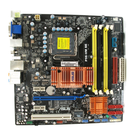
1.5.3 Motherboard layout 24.5cm (9.6in) CPU_FAN KBMS ATX12V LGA775 USB3-6 COM1 SPDIF_O1 E1394 CHA_FAN1 LAN1_USB12 PWR_FAN ® Intel AUDIO Silicon image DET_X1_1 PCIEX1_1 CR2032 3V Lithium Cell CMOS Power DET_X16_1 PCIEX16_1 ATHEROS Attansic ® Intel DET_X1_2 SATA2 SATA1 ICH9 PCIEX1_2 BIOS SATA6 SATA5... -
Page 23: Central Processing Unit (Cpu)
ASUS will shoulder the cost of repair only if the damage is shipment/transit-related. • Keep the cap after installing the motherboard. ASUS will process Return Merchandise Authorization (RMA) requests only if the motherboard comes with the cap on the LGA775 socket. -
Page 24: Installing The Cpu
Installing the CPU To install a CPU: Locate the CPU socket on the motherboard. P5E-VM SE CPU Socket 775 Before installing the CPU, make sure that the cam box is facing towards you and the load lever is on your left. - Page 25 The motherboard supports Intel LGA775 processors with the Intel Enhanced ® ® Memory 64 Technology (EM64T), Enhanced Intel SpeedStep Technology ® (EIST), and Hyper-Threading Technology. Refer to the Appendix for more information on these CPU features. ASUS P5E-VM SE 1-13...
-
Page 26: Installing The Cpu Heatsink And Fan
1.6.2 Installing the CPU heatsink and fan The Intel LGA775 processor requires a specially designed heatsink and fan ® assembly to ensure optimum thermal condition and performance. • When you buy a boxed Intel processor, the package includes the CPU fan ®... - Page 27 Connect the CPU fan cable to the connector on the motherboard labeled CPU_FAN. CPU_FAN P5E-VM SE CPU fan connector Do not forget to connect the CPU fan connector! Hardware monitoring errors can occur if you fail to plug this connector.
-
Page 28: Uninstalling The Cpu Heatsink And Fan
1.6.3 Uninstalling the CPU heatsink and fan To uninstall the CPU heatsink and fan: Disconnect the CPU fan cable from the connector on the motherboard. Rotate each fastener counterclockwise. Pull up two fasteners at a time in a diagonal sequence to disengage the heatsink and fan assembly from the motherboard. - Page 29 The narrow end of the groove should point outward after resetting. (The photo shows the groove shaded for emphasis.) Refer to the documentation in the boxed or stand-alone CPU fan package for detailed information on CPU fan installation. ASUS P5E-VM SE 1-17...
-
Page 30: System Memory
Overview The motherboard comes with four Double Data Rate 2 (DDR2) Dual Inline Memory Modules (DIMM) sockets. The figure illustrates the location of the DDR2 DIMM sockets: P5E-VM SE 240-pin DDR2 DIMM sockets Channel Sockets Channel A DIMM_A1 and DIMM_A2... - Page 31 DDR2-667. If this happens, contact your memory vendor to check the ODT value. • Due to chipset limitation, DDR2-800 with CL=4 will be downgraded to run at DDR2-667 by default setting. If you want to operate with lower latency, adjust the memory timing manually. ASUS P5E-VM SE 1-19...
- Page 32 P5E-VM SE Motherboard Qualified Vendors Lists (QVL) DDR2-800 MHz capability DIMM support Chip Size Vendor Chip No. Part No. Brand 512MB KINGSTON K4T51083QC KVR800D2N5/512 • • • 1024MB KINGSTON Heat-Sink Package 4-4-4-12 KHX6400D2LL/1G • • 1024MB KINGSTON Heat-Sink Package 4-4-4-12 KHX6400D2LLK2/1GN •...
- Page 33 P5E-VM SE Motherboard Qualified Vendors Lists (QVL) DDR2-667 MHz capability DIMM support Chip Size Vendor Chip No. Part No. Brand 512MB KINGSTON D6408TEBGGL3U KINGSTON KVR667D2N5/512 • • • 1024MB KINGSTON D6408TEBGGL3U KINGSTON KVR667D2N5/1G • • • 256MB KINGSTON HYB18T256800AF3S KVR667D2N5/256 •...
- Page 34 Dual-channel memory configuration. • C: Supports four modules inserted into the yellow slots and the black slots as two pairs of Dual-channel memory configuration. Visit the ASUS website for the latest DDR2-800/667/533 MHz QVL. 1-22 Chapter 1: Product Introduction...
-
Page 35: Installing A Dimm
DIMM. Support the DIMM lightly with your fingers when pressing the retaining clips. The DIMM might get damaged when it flips out DDR2 DIMM notch with extra force. Remove the DIMM from the socket. ASUS P5E-VM SE 1-23... -
Page 36: Expansion Slots
Expansion slots In the future, you may need to install expansion cards. The following sub-sections describe the slots and the expansion cards that they support. Make sure to unplug the power cord before adding or removing expansion cards. Failure to do so may cause you physical injury and damage motherboard components. -
Page 37: Interrupt Assignments
– – – – – SATA controller 2 – – – – – – shared – VIA 1394 – – – – shared – – – Azalia – – – – – – shared – ASUS P5E-VM SE 1-25... -
Page 38: Pci Slot
1.8.4 PCI slot The PCI slot support cards such as a LAN card, SCSI card, USB card, and other cards that comply with PCI specifications. Refer to the figure below for the location of the slot. 1.8.5 PCI Express x1 slots This motherboard supports PCI Express x1 network cards, SCSI cards and other cards that comply with the PCI Express specifications. -
Page 39: Jumper
Removing the cap will cause system boot failure! CLRTC Normal Clear RTC P5E-VM SE Clear RTC RAM (Default) • You do not need to clear the RTC when the system hangs due to overclocking. For system failure due to overclocking, use the C.P.R. (CPU Parameter Recall) feature. -
Page 40: 1.10 Connectors
1.10 Connectors 1.10.1 Rear panel connectors PS/2 mouse port (green). This port is for a PS/2 mouse. VGA port. This port is for a VGA monitor or other VGA-compatible devices. LAN (RJ-45) port. Supported by Gigabit LAN controller, this port allows Gigabit connection to a Local Area Network (LAN) through a network hub. - Page 41 S/PDIF cable. 13. USB 2.0 ports 3-6. These four 4-pin Universal Serial Bus (USB) ports are available for connecting USB 2.0 devices. 14. PS/2 keyboard port (purple). This port is for a PS/2 keyboard. ASUS P5E-VM SE 1-29...
-
Page 42: Internal Connectors
NOTE: Orient the red markings on the floppy ribbon cable to PIN 1. PIN 1 P5E-VM SE Floppy disk drive connector IDE connector (40-1 pin PRI_EIDE) The onboard IDE connector is for the Ultra DMA 133/100/66 signal cable. There are three connectors on each Ultra DMA 133/100/66 signal cable: blue, black, and gray. -
Page 43: Serial Ata Hard Disk Drive Connection
SATA2 SATA1 SATA6 SATA5 P5E-VM SE SATA connectors When using the connectors in Standard IDE mode, connect the primary (boot) hard disk drive to the SATA1/2 connector. Refer to the table below for the recommended SATA hard disk drive connections. - Page 44 Never connect a 1394 cable to the USB connectors. Doing so will damage the motherboard! You can connect the front panel USB cable to the ASUS Q-Connector (USB, blue) first, and then install the Q-Connector (USB) to the USB connector onboard if your chassis supports front panel USB ports.
- Page 45 Never connect a USB cable to the IEEE 1394a connector. Doing so will damage the motherboard! You can connect the front panel 1394 cable to the ASUS Q-Connector (1394, red) first, and then install the Q-Connector (1394) to the 1394 connector onboard if your chassis supports front panel 1394 ports.
- Page 46 Rotation +12V P5E-VM SE Fan connectors Only the CPU-FAN connectors support the ASUS Q-FAN 2 feature. Serial port connector (10-1 pin COM1) This connector is for a serial (COM) port. Connect the serial port module cable to this connector, then install the module to a slot opening at the back of the system chassis.
- Page 47 HD Audio-compliant Legacy AC ‘97 audio pin definition pin definition P5E-VM SE Analog front panel connector • We recommend that you connect a high-definition front panel audio module to this connector to avail of the motherboard’s high-definition audio capability. •...
- Page 48 PSON# Ground Ground +3 Volts -12 Volts P5E-VM SE ATX power connectors +3 Volts +3 Volts • For a fully configured system, we recommend that you use a power supply unit (PSU) that complies with ATX 12V Specification 2.0 (or later version) and provides a minimum power of 400 W.
-
Page 49: System Panel Connector
RESET IDE_LED PWRSW Requires an ATX power supply. P5E-VM SE System panel connector • System power LED (2-pin PLED) This 2-pin connector is for the system power LED. Connect the chassis power LED cable to this connector. The system power LED lights up when you turn on the system power, and blinks when the system is in sleep mode. - Page 50 Q-Connector (system panel) You can use ASUS Q-Connector to connect / disconnect chassis front panel cables by only a few steps. Directions below shows how to install ASUS Q-Connector. Step1. Connect correct front panel to ASUS Q-Connector first. You can refer to the marking on Q-Connector itself to know the detail pin definition.
-
Page 51: Chapter 2: Bios Setup
This chapter tells how to change the system settings through the BIOS Setup menus. Detailed descriptions of the BIOS parameters are also provided. Chapter 2: BIOS setup... -
Page 52: Managing And Updating Your Bios
ASUS Update (Updates the BIOS in Windows environment.) ® ASUS EZ Flash 2 (Updates the BIOS using a floppy disk or USB flash disk.) AFUDOS utility (Updates the BIOS using a bootable floppy disk.) ASUS CrashFree BIOS 3 (Updates the BIOS using a bootable floppy disk, USB flash disk or the motherboard support CD when the BIOS file fails or gets corrupted.) - Page 53 To update the BIOS through the Internet: desktop by clicking Start Launch the ASUS Update utility from the Windows ® > Programs > ASUS > ASUSUpdate > ASUSUpdate. The ASUS Update main window appears. Select Update BIOS from the Select the ASUS FTP site nearest...
- Page 54 To update the BIOS through a BIOS file: desktop by clicking Start Launch the ASUS Update utility from the Windows ® > Programs > ASUS > ASUSUpdate > ASUSUpdate. The ASUS Update main window appears. Select Update BIOS from a file option from the drop-down menu, then click Next.
-
Page 55: Creating A Bootable Floppy Disk
Click File from the menu, then select Format. A Format 3 1/2 Floppy Disk window appears. e. Select Create an MS-DOS startup disk from the format options field, then click Start. Copy the original or the latest motherboard BIOS file to the bootable floppy disk. ASUS P5E-VM SE... -
Page 56: Asus Ez Flash 2 Utility
2.1.3 ASUS EZ Flash 2 utility The ASUS EZ Flash 2 feature allows you to update the BIOS without having to go through the long process of booting from a floppy disk and using a DOS-based utility. The EZ Flash 2 utility is built-in the BIOS chip so it is accessible by pressing <Alt>... -
Page 57: Afudos Utility
The utility returns to the DOS prompt after copying the current BIOS file. Updating the BIOS file To update the BIOS file using the AFUDOS utility: Visit the ASUS website (www.asus.com) and download the latest BIOS file for the motherboard. Save the BIOS file to a bootable floppy disk. ASUS P5E-VM SE... - Page 58 A:\>afudos /iP5E-VM SE.ROM The utility verifies the file and starts updating the BIOS. A:\>afudos /iP5E-VM SE.ROM AMI Firmware Update Utility - Version 1.19(ASUS V2.07(03.11.24BB)) Copyright (C) 2002 American Megatrends, Inc. All rights reserved. WARNING!! Do not turn off power during flash BIOS Reading file ..
-
Page 59: Asus Crashfree Bios 3 Utility
2.1.5 ASUS CrashFree BIOS 3 utility The ASUS CrashFree BIOS 3 is an auto recovery tool that allows you to restore the BIOS file when it fails or gets corrupted during the updating process. You can update a corrupted BIOS file using the motherboard support CD, the floppy disk, or the USB flash disk that contains the updated BIOS file. -
Page 60: Bios Setup Program
The BIOS setup screens shown in this section are for reference purposes only, and may not exactly match what you see on your screen. • Visit the ASUS website (www.asus.com) to download the latest BIOS file for this motherboard. 2-10... -
Page 61: Bios Menu Screen
At the bottom right corner of a menu screen are the navigation keys for that particular menu. Use the navigation keys to select items in the menu and change the settings. Some of the navigation keys differ from one screen to another. ASUS P5E-VM SE 2-11... -
Page 62: Menu Items
2.2.4 Menu items The highlighted item on the menu bar displays the specific items for that Use [ENTER], [TAB], System Time [06:22:54] or [SHIFT-TAB] to System Date [Mon 01/28/2008] select a field. menu. For example, selecting Main Legacy Diskette A [1.44M, 3.5 in] Language [English]... -
Page 63: Main Menu
Legacy Diskette A [1.44M, 3.5 in.] Sets the type of floppy drive installed. Configuration options: [Disabled] [720K, 3.5 in.] [1.44M, 3.5 in.] 2.3.4 Language [English] Allows you to select the display language for the BIOS setup screen. Configuration options: [English] ASUS P5E-VM SE 2-13... -
Page 64: Sata 1/2/5/6; Pata Primary Master/Slave
2.3.5 SATA 1/2/5/6; PATA Primary Master/Slave While entering Setup, the BIOS automatically detects the presence of IDE devices. There is a separate sub-menu for each IDE device. Select a device item then press <Enter> to display the IDE device information. BIOS SETUP UTILITY Main SATA 1... -
Page 65: Sata Configuration
Disables or enables device write protection. This will be effective only if device is accessed throuh BIOS. Confiuration option: [Disabled] [Enabled] SATA Detect Time Out (Sec) [35] Selects the time out value for detecting ATA/ATAPI devices. Configuration options: [0] [5] [10] [15] [20] [25] [30] [35] ASUS P5E-VM SE 2-15... -
Page 66: System Information
2.3.7 System Information This menu gives you an overview of the general system specifications. The BIOS automatically detects the items in this menu. BIOS SETUP UTILITY Main AMIBIOS Version : 0103 Build Date : 01/15/08 Processor Type : Intel(R) Core(TM)2 Duo CPU @ 3.00GHz Speed : 3000 MHz Count... -
Page 67: Advanced Menu
Loads the optimal settings for the system. Standard Loads the standard settings for the system. N.O.S. The ASUS Non-delay Overclocking System feature intelligently determines the system load and automatically boosts the performance for the most demanding tasks. ASUS P5E-VM SE... - Page 68 Some of the following items appear when you set AI Overclocking to [Manual] and [N.O.S.] CPU Ratio Setting [Auto] Allows you to set the ratio between CPU core clock and the FSB frequency. Use the <+> and <-> keys to select the ratio values. Configuration options: [Auto] [14.0] [15.0] ~ [23.0] [24.0] FSB Strap to North Bridge [Auto] FSB Strap will be adjusted automatically by FSB Frequency and DRAM Frequency.
- Page 69 CPU Spread Spectrum [Auto] Allows you to enable or disable the CPU spread spectrum. Configuration options: [Auto] [Disabled] PCIE Spread Spectrum [Auto] Allows you to enable or disable the PCIE spread spectrum. Configuration options: [Auto] [Disabled] ASUS P5E-VM SE 2-19...
- Page 70 CPU Voltage [Auto] Allows you to select the CPU voltage. Configuration options: [Auto] [1.7000V] [1.6875V] [1.6750V] [1.6625V] [1.6500V] [1.6375V] [1.6250V] [1.6125V] [1.6000V] [1.5875V] [1.5750V] [1.5625V] [1.5500V] [1.5375V] [1.5250V] [1.5125V] [1.5000V] [1.4875V] [1.4750V] [1.4625V] [1.4500V] [1.4375V] [1.4250V] [1.4125V] [1.4000V] [1.3875V] [1.3750V] [1.3625V] [1.3500V] [1.3375V] [1.3250V] [1.3125V] [1.3000V] [1.2875V] [1.2750V] [1.2625V] [1.2500V] [1.2375V] [1.2250V] [1.2125V] [1.2000V] [1.1875V] [1.1750V] [1.1625V] [1.1500V] [1.1375V] [1.1250V] [1.1125V] [1.1000V] Refer to the CPU documentation before setting the CPU voltage.
-
Page 71: Ai Net 2
The USB Devices Enabled item shows auto-detected values. If no USB device is detected, the item shows None. USB Functions [Enabled] Allows you to enable or disable the USB functions. The following sub-items appear when this item is set to [Enabled]. Configuration options: [Disabled] [Enabled] ASUS P5E-VM SE 2-21... - Page 72 USB 2.0 Controller [Enabled] Allows you to enable or disable the USB 2.0 controller. Configuration options: [Enabled] [Disabled] USB 2.0 Controller Mode [HiSpeed] Allows you to set the USB 2.0 controller mode to HiSpeed (480 Mbps) or FullSpeed (12 Mbps). This item appears only when you enable the USB 2.0 Controller item.
-
Page 73: Cpu Configuration
Configuration options: [Disabled] [Enabled] Execute Disable Bit [Enabled] Allows you to enable or disable the No-Execution Page Protection Technology. Setting this item to [Disabled] forces the XD feature flag to always return to zero (0). Configuration options: [Disabled] [Enabled] ASUS P5E-VM SE 2-23... -
Page 74: Chipset
2.4.5 Chipset The Chipset menu allows you to change the advanced chipset settings. Select an item then press <Enter> to display the sub-menu. BIOS SETUP UTILITY Advanced Advanced Chipset Settings Configure North Bridge features. WARMING: Setting wrong values in below sections may cause system to malfunction. - Page 75 Video Function Configuration Options Fixed Mode DVMT Mode Select [DVMT Mode] DVMT Mode DVMT/FIXED Memory [256MB] DVMT Mode Select [DVMT Mode] Configuration options: [Fixed Mode] [DVMT Mode] DVMT/FIXED Memory [256MB] Configuration options: [128MB] [256MB] [Maximum DVMT] ASUS P5E-VM SE 2-25...
-
Page 76: Onboard Devices Configuration
2.4.6 Onboard Devices Configuration BIOS SETUP UTILITY Advanced Onboard Device Configuraiton Enable or Disable High Definition Audio Controller High Definition Audio [Enabled] Front Panel Type [HD Audio] Onboard 1394 Controller [Enabled] Onboard PCIE GbE LAN [Enabled] LAN Option ROM [Disabled] J-Micron PATA Controller [Enabled] Serial Port1 Address... -
Page 77: Pcipnp
When set to [NO], BIOS configures all the devices in the system. When set to [YES] and if you install a Plug and Play operating system, the operating system configures the Plug and Play devices not required for boot. Configuration options: [NO] [YES] ASUS P5E-VM SE 2-27... -
Page 78: Power Menu
Power menu The Power menu items allow you to change the settings for the Advanced Power Management (APM). Select an item then press <Enter> to display the configuration options. BIOS SETUP UTILITY Main Advanced Power Boot Tools Exit Select the ACPI state Suspend Mode [Auto] used for System... -
Page 79: Apm Configuration
Allows you to enable or disable the PME to wake up from S5 by PCI devices. Configuration options: [Disabled] [Enabled] Power On By PCIE Devices [Disabled] Allows you to enable or disable the PCIE devices to generate a wake event. Configuration options: [Disabled] [Enabled] ASUS P5E-VM SE 2-29... -
Page 80: Hardware Monitor
Power On By PS/2 Keyboard [Disabled] Allows you to disable the Power On by PS/2 keyboard function or set specific keys on the PS/2 keyboard to turn on the system. This feature requires an ATX power supply that provides at least 1A on the +5VSB lead. Configuration options: [Disabled] [Space Bar] [Ctrl-Esc] [Power Key] Power On By PS/2 Mouse [Disabled] When set to [Enabled], this parameter allows you to use the PS/2 mouse to turn on... - Page 81 N/A. Vcore Voltage, 3.3V Voltage, 5V Voltage, 12V Voltage The onboard hardware monitor automatically detects the voltage output through the onboard voltage regulators. Select [Ignored] if you do not want to detect this item. ASUS P5E-VM SE 2-31...
-
Page 82: Boot Menu
Boot menu The Boot menu items allow you to change the system boot options. Select an item then press <Enter> to display the sub-menu. BIOS SETUP UTILITY Main Advanced Power Boot Tools Exit Specifies the Boot Device Priority Boot Device Priority sequence. -
Page 83: Boot Settings Configuration
BIOS performs all the POST items. Configuration options: [Disabled] [Enabled] Full Screen Logo [Enabled] This allows you to enable or disable the full screen logo display feature. Configuration options: [Disabled] [Enabled] Set this item to [Enabled] to use the ASUS MyLogo3 feature. ™ AddOn ROM Display Mode [Force BIOS] Sets the display mode for option ROM. -
Page 84: Security
2.6.3 Security The Security menu items allow you to change the system security settings. Select an item then press <Enter> to display the configuration options. BIOS SETUP UTILITY Boot <Enter> to change Security Settings password. <Enter> again to Supervisor Password :Not Installed disabled password. -
Page 85: Change User Password
Password Check [Setup] When set to [Setup], BIOS checks for user password when accessing the Setup utility. When set to [Always], BIOS checks for user password both when accessing Setup and booting the system. Configuration options: [Setup] [Always] ASUS P5E-VM SE 2-35... -
Page 86: Tools Menu
2.7.1 ASUS EZ Flash 2 Allows you to run ASUS EZ Flash 2. When you press <Enter>, a confirmation message appears. Use the left/right arrow key to select between [Ok] or [Cancel], then press <Enter> to confirm your choice. Please see section 2.1.3 for details. -
Page 87: Asus O.c. Profile
This function can support devices such as USB flash disk or floppy disk with FAT 32/16 format and single partition only. • DO NOT shut down or reset the system while updating the BIOS to prevent the system boot failure! ASUS P5E-VM SE 2-37... -
Page 88: Ai Net 2
2.7.3 Ai Net 2 BIOS SETUP UTILITY Advanced Ai Net 2 Options Pair Status Length Disabled Enhanced Atheros Controller 0 Atheros POST Check LAN cable [Disabled] Select Screen Select Item Change Option General Help Save and Exit Exit v02.58 (C)Copyright 1985-2007, American Megatrends, Inc. Atheros POST Check LAN cable [Disabled] Enables or disables checking of the LAN cable during the Power-On Self-Test (POST). -
Page 89: Exit Menu
Setup menus. When you select this option or if you press <F5>, a confirmation window appears. Select Ok to load default values. Select Exit & Save Changes or make other changes before saving the values to the non-volatile RAM. ASUS P5E-VM SE 2-39... - Page 90 2-40 Chapter 2: BIOS setup...
-
Page 91: Chapter 3: Software Support
This chapter describes the contents of the support CD that comes with the motherboard package. Chapter 3: Software support... -
Page 92: Installing An Operating System
The contents of the support CD are subject to change at any time without notice. Visit the ASUS website (www.asus.com) for updates. 3.2.1 Running the support CD Place the support CD to the optical drive. -
Page 93: Drivers Menu
Installs the Realtek ALC883 audio driver and application. ® If you install drivers separately instead of using ASUS InstAll-Drivers Installation Wizard, make sure to install these drivers in the following order: 1. Intel Chipset Inf Update Program 2. Realtek Audio Driver 3. -
Page 94: Utilities Menu
Installs all of the utilities through the Installation Wizard. ASUS Update Allows you to download the latest version of the BIOS from the ASUS website. Before using the ASUS Update, make sure that you have an Internet connection so you can connect to the ASUS website. - Page 95 You can also install the following utilities from the ASUS Superb Software Library CD. Anti-Virus Utility The anti-virus application detects and protects your computer from viruses that destroys data. You can also download the utility by clicking the Security tab.
-
Page 96: Manual Menu
(www.microsoft.com) for updates. ASUS Motherboard Installation Guide The ASUS Motherboard Installation Guide contains a general and clear instruction on how to install your new ASUS motherboard, FAQs, and how to maintain your 3.2.4 Manual menu The Manual menu contains a list of supplementary user manuals. Click an item to open the folder of the user manual. -
Page 97: Asus Contact Information
3.2.5 ASUS Contact information Click the Contact tab to display the ASUS contact information. You can also find this information on the inside front cover of this user guide. 3.2.6 Other information The icons on the top right corner of the screen give additional information on the motherboard and the contents of the support CD. -
Page 98: Technical Support Form
Browse this CD Displays the support CD contents in graphical format. Technical support Form Displays the ASUS Technical Support Request Form that you have to fill out when requesting technical support. Filelist Displays the contents of the support CD and a brief description of each in text format. -
Page 99: Appendix: Cpu Features
The Appendix describes the CPU features and technologies that the motherboard supports. Appendix: CPU features... -
Page 100: Intel ® Em64T
32-bit operating systems. • The motherboard comes with a BIOS file that supports EM64T. You can download the latest BIOS file from the ASUS website (www.asus.com/ support/download/) if you need to update the BIOS file. See Chapter 2 for details. -
Page 101: Using The Eist
Click Apply, then click OK. 10. Close the Display Properties window. After you adjust the power scheme, the CPU internal frequency slightly decreases when the CPU loading is low. The screen displays and procedures may vary depending on the operating system. ASUS P5E-VM SE... -
Page 102: Intel ® Hyper-Threading Technology
® Intel Hyper-Threading Technology • The motherboard supports Intel Pentium 4 LGA775 processors with ® ® Hyper-Threading Technology. • Hyper-Threading Technology is supported under Windows ® Vista/XP and Linux 2.4.x (kernel) and later versions only. Under Linux, use the Hyper- Threading compiler to compile the code.