
Related Manuals for Acer eMachines eM250 Series


Summary of Contents for Acer eMachines eM250 Series
-
Page 1: Emachines Em250 Series
Series Service Guide Service guide files and updates are available on the ACER/CSD web; for more information, please refer to http://csd.acer.com.tw PRINTED IN TAIWAN... -
Page 2: Revision History
Revision History Please refer to the table below for the updates made to this service guide. Date Chapter Updates... - Page 3 Copyright Copyright © 2009 by Acer Incorporated. All rights reserved. No part of this publication may be reproduced, transmitted, transcribed, stored in a retrieval system, or translated into any language or computer language, in any form or by any means, electronic, mechanical, magnetic, optical, chemical, manual or otherwise, without the prior written permission of Acer Incorporated.
- Page 4 Conventions The following conventions are used in this manual: Denotes actual messages that appear SCREEN MESSAGES on screen. NOTE Gives bits and pieces of additional information related to the current topic. WARNING Alerts you to any damage that might result from doing or not doing specific actions.
- Page 5 DIFFERENT part number code to those given in the FRU list of this printed Service Guide. You MUST use the list provided by your regional Acer office to order FRU parts for repair and service of customer machines.
-
Page 7: Table Of Contents
Table of Contents System Specifications Features ............1 System Block Diagram . - Page 8 Table of Contents Removing the Mainboard ......... .63 Removing the RTC Battery .
- Page 9 Table of Contents External Mouse Failure ......... . .134 Other Failures .
- Page 10 Table of Contents...
-
Page 11: System Specifications
Supports 512 MB / 1 GB / 2 GB soDIMMs for total system memory of up to 2 GB Display and graphics • 10.1" WSVGA high-brightness (typical 180-nit) Acer CrystalBrite™ TFT LCD, 1024 x 600 pixel resolution •... -
Page 12: Privacy Control
1.33 kg (2.95 lbs.) for SKUs with 6-cell battery pack Communication • Integrated webcam, supporting 0.3-megapixel resolution • WLAN: Acer InviLink™ 802.11b/g Wi-Fi CERTIFIED® network connection, supporting Acer SignalUp™ wireless technology • LAN: 10/100 Mbps Fast Ethernet • WPAN: Bluetooth® 2.0+EDR •... -
Page 13: System Block Diagram
System Block Diagram Diamondville SC FCBGA8 437Pins 22x22mm page 4,5 Clock Generator CRT Conn CK505 3 . . 400/533MHz 6 . . page 12 page 14 Memory BUS(DDRII) DDRII-SO-DIMM Calistoga GSE page 11 FCBGA998 1.8V DDRII 400/533 LCD Conn. LVDS Thermal Sensor 27x27mm page 13... -
Page 14: Your Emachines Notebook Tour
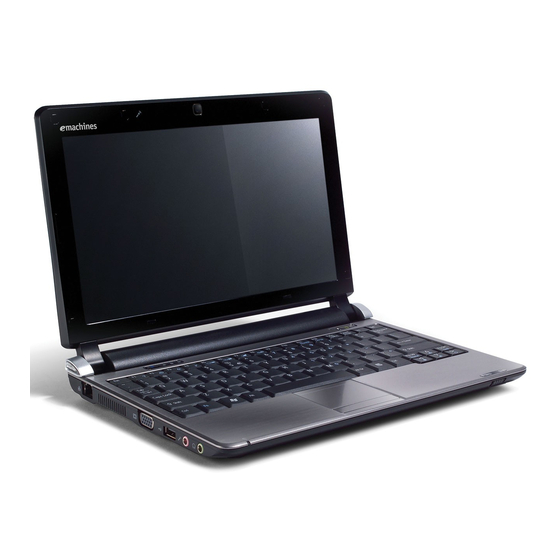
Your eMachines Notebook tour Front View Icon Item Description Webcam Web camera for video communication Microphone Internal microphone for sound recording. Display screen Also called Liquid-Crystal Display (LCD), displays computer output. Bluetooth Enables/disables the Bluetooth function. communication Indicates the status of Bluetooth communication. switch/indicator (only for certain models) Status indicators... -
Page 15: Closed Front View
Icon Item Description Click buttons (left The left and right buttons function like the left and and right) right mouse buttons. Wireless LAN/3G Indicates the status of Wireless LAN/3G communication communication. (only for certain models) indicator Power button/ Turns the computer on and off. indicator Closed Front View Icon... -
Page 16: Right View
Right View Icon Item Description Multi-in-1 card Accepts Secure Digital (SD), MultiMediaCard reader (MMC), Memory Stick (MS), Memory Stick PRO (MS PRO), xD-Picture Card (xD). Note: Push to remove/install the card. Only one card can operate at any given time. USB 2.0 ports Connect to USB 2.0 devices (e.g. -
Page 17: Indicators
Icon Item Description Battery lock Locks the battery in position. Ventilation slots Vents enable the computer to stay cool, even after prolonged use. Note: Do not cover or obstruct the cooling vents. Battery release Releases the battery for removal. latch 3G SIM card slot Accepts a 3G SIM card for 3G connectivity (only for certain models). -
Page 18: Touchpad Basics
TouchPad Basics The following items show you how to use the TouchPad: • Move your finger across the TouchPad (1) to move the cursor. • Press the left (2) and right (3) buttons located beneath the TouchPad to perform selection and execution functions. -
Page 19: Using The Keyboard
Using the Keyboard Your eMachines eM250 has a close-to-full-sized keyboard and an embedded numeric keypad, separate cursor, lock, function and special keys. Lock Keys and embedded numeric keypad The keyboard has three lock keys which you can toggle on and off. Lock key Description Caps Lock... -
Page 20: Windows Keys
Windows Keys The keyboard has two keys that perform Windows-specific functions. Description Windows key Pressed alone, this key has the same effect as clicking on the Windows Start button; it launches the Start menu. It can also be used with other keys to provide a variety of functions: <... -
Page 21: Hot Keys
Icon Function Description <Fn> + <F1> Hotkey help Displays help on hotkeys. <Fn> + <F2> Acer eSettings Launches Acer eSettings Management in Acer Management Empowering Technology. <Fn> + <F3> Acer ePower Launches Acer ePower Management in Acer Management Empowering Technology. -
Page 22: Special Keys
Special Keys You can locate the Euro symbol and the US dollar sign at the upper-center and/or bottom-right of your keyboard. The Euro symbol Open a text editor or word processor. Hold <Alt Gr> and then press the <5> key at the upper-center of the keyboard. NOTE: Some fonts and software do not support the Euro symbol. -
Page 23: Hardware Specifications And Configurations
• Advanced power management features including Enhanced Intel SpeedStep® Technology • Execute Disable Bit support for enhanced security Processor Specifications Cache Core Item Cores Package Acer P/N Speed Speed Tech Size Voltage N270 1.6 GHz 533 MHz 45 nm Micro- 0.9V-... - Page 24 System Memory Item Specification Memory controller Built in Memory size 512MB or 1GB DDR2 RAM (if 2Gb die support is available) DIMM socket number Supports memory size per socket 2 GB Supports maximum memory size 2 GB Supports DIMM type DDR II 533Mhz SDRAM memory interface design Supports DIMM Speed 533Mhz SDRAM...
- Page 25 BIOS Version v0.10 BIOS ROM type Flash BIOS ROM size 1 MB Features • Support ISIPP • Support Acer UI • Support multi-boot • Suspend to RAM (S3)/Disk (S4) • Various hot-keys for system control • Support SMBUS 2.0, PCI2.3 •...
- Page 26 Supports 1.5V~3.3V scalable I/O for HD Audio link • 48-pin LQFP ‘Green’ package LAN Interface Item Specification LAN Chipset Atheros AR8114/AR8132 Features • Supports 10/100 Keyboard Item Specification Type New Acer flat keyboard Total number of keypads 84/88 with 101/102 key emulation Windows logo key Chapter 1...
- Page 27 Item Specification Internal & external keyboard work Plug USB keyboard to the USB port directly: Yes simultaneously Features • 2.0+/- 3mm full stroke keys • Phantom key auto detect • Overlay numeric keypad • Support independent pgdn/pgup/pgup/home/end keys • Support reverse T cursor keys •...
- Page 28 Chapter 1...
-
Page 29: System Utilities
Chapter 2 System Utilities BIOS Setup Utility The BIOS Setup Utility is a hardware configuration program built into your computer’s BIOS (Basic Input/ Output System). Your computer is already properly configured and optimized, and you do not need to run this utility. However, if you encounter configuration problems, you may need to run Setup. -
Page 30: Information
Information The Information screen displays a summary of your computer hardware information. I n s y d e H 2 0 S e t u p U t i l i t y R e v . 3 . 5 Information Main Security... -
Page 31: Main
Main The Main screen allows the user to set the system time and date as well as enable and disable boot option and recovery. I n s y d e H 2 0 S e t u p U t i l i t y R e v . -
Page 32: Security
Security The Security screen contains parameters that help safeguard and protect your computer from unauthorized use. I n s y d e H 2 0 S e t u p U t i l i t y R e v . 3 . 5 Information Main Security... -
Page 33: Setting A Password
Setting a Password Follow these steps as you set the user or the supervisor password: Use the ↑ and ↓ keys to highlight the Set Supervisor Password parameter and press the Enter key. The Set Supervisor Password box appears: S e t S u p e r v i s o r P a s s w o r d E n t e r N e w P a s s w o r d C o n f i r m N e w P a s s w o r d Type a password in the “Enter New Password”... -
Page 34: Changing A Password
Changing a Password Use the ↑ and ↓ keys to highlight the Set Supervisor Password parameter and press the Enter key. The Set Password box appears. S e t S u p e r v i s o r P a s s w o r d E n t e r C u r r e n t P a s s w o r d E n t e r N e w P a s s w o r d C o n f i r m N e w P a s s w o r d... -
Page 35: Boot
Boot This menu allows the user to decide the order of boot devices to load the operating system. Bootable devices includes the USB diskette drives, the onboard hard disk drive and the DVD drive in the module bay. I n s y d e H 2 0 S e t u p U t i l i t y R e v . -
Page 36: Exit
Exit The Exit screen allows you to save or discard any changes you made and quit the BIOS Utility. I n s y d e H 2 0 S e t u p U t i l i t y R e v . -
Page 37: Bios Flash Utility
BIOS Flash Utility The BIOS flash memory update is required for the following conditions: • New versions of system programs • New features or options • Restore a BIOS when it becomes corrupted. Use the Phlash utility to update the system BIOS flash ROM. NOTE: If you do not have a crisis recovery diskette at hand, then you should create a Crisis Recovery Diskette before you use the Phlash utility. -
Page 38: Dos Flash Utility
DOS Flash Utility Perform the following steps to use the DOS Flash Utility: Press F2 during boot to enter the Setup Menu. Select Boot Menu to modify the boot priority order, for example, if using USB HDD to Update BIOS, move USB HDD to position 1. - Page 39 NOTE: If the AC power is not connected, the following message displays. Plug in the AC power to continue. Flash is complete when the message Flash programming complete displays. Chapter 2...
-
Page 40: Winflash Utility
WinFlash Utility Perform the following steps to use the WinFlash Utility: Double click the WinFlash executable. Click OK to begin the update. A progress screen displays. When the process is complete, close all programs and applications and reboot the system. Chapter 2... -
Page 41: Remove Hdd/Bios Password Utilities
Remove HDD/BIOS Password Utilities This section provides you with details about removing HDD/BIOS password methods: Removing HDD Password: If you key in the wrong HDD password three times, an error is generated. To reset the HDD password, perform the following steps: After the error is displayed, select the Enter Unlock Password option on the screen. - Page 42 Removing BIOS Passwords: To clear the User or Supervisor passwords, open the 3G bay door and use a metal instrument to short the RTC_RST jumper as shown below. Cleaning BIOS Passwords To clean the User or Supervisor passwords, perform the following steps: From a DOS prompt, execute clnpwd.exe Press 1 or 2 to clean the desired password shown on the screen.
-
Page 43: Miscellaneous Utilities
Miscellaneous Utilities Using Boot Sequence Selector Boot Sequence Selector allows the boot order to be changes without accessing the BIOS. To use Boot Sequence Selector, perform the following steps: Enter into DOS. Execute BS.exe to display the usage screen. Select the desired boot sequence by entering the corresponding sequence, for example, enter BS2 to change the boot sequence to HDD|CD ROM|LAN|Floppy. - Page 44 Manufacturer (Type1, Offset04h): Acer Product Name (Type1, Offset05h): eMachines eM250 xxxxx Serial Number (Type1, Offset07h): 01234567890123456789 UUID String (Type1, Offset08h): xxxxxxxx-xxxx-xxxx-xxxx-xxxxxxxxxxxx Asset Tag (Type3, Offset04h): Acer Asstag Example 2: Write Product Name to EEPROM Input: dmitools /wp Acer Example 3: Write Serial Number to EEPROM...
- Page 45 Execute MAC.BAT to write MAC information to eeprom. Chapter 2...
- Page 46 Chapter 2...
-
Page 47: Machine Disassembly And Replacement
Chapter 3 Machine Disassembly and Replacement This chapter contains step-by-step procedures on how to disassemble the notebook computer for maintenance and troubleshooting. Disassembly Requirements To disassemble the computer, you need the following tools: Wrist grounding strap and conductive mat for preventing electrostatic discharge •... -
Page 48: General Information
General Information Pre-disassembly Instructions Before proceeding with the disassembly procedure, make sure that you do the following: 1. Turn off the power to the system and all peripherals. 2. Unplug the AC adapter and all power and signal cables from the system. 3. -
Page 49: External Module Disassembly Process
External Module Disassembly Process NOTE: The product previews seen in the disassembly procedures may not represent the final product color or configuration. External Modules Disassembly Flowchart Turn off system and peripherals power Disconnect power and signal cables from system Remove Battery Remove Lower Covers... -
Page 50: Removing The Battery Pack
Removing the Battery Pack 1. Turn the computer over. 2. Slide the battery lock/unlock latch to the unlock position. 3. Slide and hold the battery release latch to the release position (1), then slide out the battery pack from the main unit (2). -
Page 51: Removing The Lower Covers
Removing the Lower Covers 1. See “Removing the Battery Pack” on page 40. 2. Remove the four from the HDD, Memory, and 3G Covers. Step Size Quantity Screw Type Lower Covers M2*4 3. Lift the HDD cover up to remove. Chapter 3... - Page 52 4. Lift the Memory cover up to remove. 5. Lift the 3G cover up to remove. Chapter 3...
-
Page 53: Removing The Hard Disk Drive Module
Removing the Hard Disk Drive Module 1. See “Removing the Lower Covers” on page 41. 2. Remove the single screw securing the HDD Module in place. Step Size Quantity Screw Type HDD Module M2*4 3. Slide the HDD in the direction of the arrow to disconnect the HDD from the interface connector. Chapter 3... - Page 54 4. Lift the hard disk drive module out of the bay. NOTE: To prevent damage to device, avoid pressing down on it or placing heavy objects on top of it. 5. Remove the four screws (two each side) securing the hard disk to the carrier. Step Size Quantity...
-
Page 55: Removing The Dimm Module
Removing the DIMM Module 1. See “Removing the Lower Covers” on page 41. 2. Push out the release latches on both sides of the DIMM socket to release the DIMM module. 3. Remove the DIMM module. Chapter 3... -
Page 56: Removing The 3G Module
Removing the 3G Module IMPORTANT: 3G functionality is not supported by all models. 1. See “Removing the Lower Covers” on page 41. 2. Disconnect the 3G Antenna cables from the 3G Module. IMPORTANT: The Blue cable attaches to the MAIN terminal and the Yellow cable attaches to the AUX terminal. 3. - Page 57 4. Detach the 3G Module from the socket. NOTE: When reattaching the antennas, ensure the cables are tucked into the chassis to prevent damage. Chapter 3...
-
Page 58: Main Unit Disassembly Process
Main Unit Disassembly Process IMPORTANT: Cable paths and positioning may not represent the actual model. During the removal and replacement of components, ensure all available cable channels and clips are used and that the cables are replaced in the same position. NOTE: The product previews seen in the disassembly procedures may not represent the final product color or configuration. -
Page 59: Removing The Keyboard
Removing the Keyboard 1. See “Removing the Battery Pack” on page 40. 2. Turn the computer rightside up and open the lid to the full extent. 3. Unlock the single securing latch above the F8 key by pressing down with plastic tweezers. IMPORTANT: The use of metal tools may damage the outer casing. - Page 60 6. Disconnect the FFC and remove the Keyboard. Chapter 3...
-
Page 61: Removing The Upper Cover
Removing the Upper Cover 1. See “Removing the Keyboard” on page 49. 2. Turn the computer over. Remove the eleven securing screws. Step Size Quantity Screw Type Upper Cover M2*3 (red callouts) Upper Cover M2*4 (green callouts) Upper Cover M2*12 (blue callout) 3. - Page 62 Release the locking latch on A as shown. Disconnect A from the Mainboard. Release the locking latch on B as shown. Disconnect B from the Mainboard. Disconnect C as shown. Chapter 3...
- Page 63 4. Remove the five securing screws from the Upper Cover. Step Size Quantity Screw Type Upper Cover M2*4 CAUTION: Cables are placed inside the Hinge Cover Caps. When disassembling the panel or covers, take care to dislodge the cables from the base to prevent damage. 5.
- Page 64 7. Lift the left side of the Upper Cover away from the Lower Cover. 8. Lift the Upper Cover clear of the Lower Cover. Chapter 3...
-
Page 65: Removing The Power Board
Removing the Power Board 1. See “Removing the Upper Cover” on page 51. 2. Lift the Power Board FFC to detach the adhesive securing it in place. 3. Turn the Upper Cover over and remove the single screw securing the Power Board in place. Step Size Quantity... - Page 66 4. Slide the Power Board to the right to disengage the locating pin. 5. Lift the mylar sheet away from the Upper Cover to allow the Power Board FFC to pass through the cover. 6. Remove the board from the Upper Cover. Chapter 3...
-
Page 67: Removing The Bluetooth Module
Removing the Bluetooth Module 1. See “Removing the Upper Cover” on page 51. 2. Remove the Bluetooth Module cable from the cable channel. Ensure that the cable is free from all cable clips. 3. Lift the Bluetooth Module, left side first, to remove it from the Upper Cover. NOTE: The Bluetooth Module is held in place by a single screw (M2*3) on some models. -
Page 68: Removing The Touchpad Ffc
Removing the TouchPad FFC IMPORTANT: The TouchPad Board cannot be removed individually. To replace the TouchPad Board, replace the entire Upper Cover. 1. See “Removing the Upper Cover” on page 51. 2. Hold the mylar sheet in place and lift the FFC away from the Upper Cover. 3. -
Page 69: Removing The Wlan Board
Removing the WLAN Board 1. See “Removing the Upper Cover” on page 51. 2. Disconnect the Antenna cables from the WLAN Board. NOTE: Cable placement is Black to the MAIN terminal (left) and White to the AUX terminal (right). 3. Remove the single screw securing the WLAN Board in place. Step Size Quantity... - Page 70 4. Remove the WLAN Board from the Mainboard. Chapter 3...
-
Page 71: Removing The Usb Board
Removing the USB Board 1. See “Removing the Upper Cover” on page 51. 2. Remove the single screw securing the USB Board to the Lower Cover. Step Size Quantity Screw Type USB Board M2*4 3. Lift the USB Board, left side first to free the I/O ports from the Lower Cover. IMPORTANT: Do not fully remove the USB Board from the cover;... - Page 72 4. Turn the board over to expose the cable connector. Detach the adhesive strip holding the cable in place. 5. Disconnect the cable from the USB Board. 6. Remove the USB Board from the Lower Cover. Chapter 3...
-
Page 73: Removing The Mainboard
Removing the Mainboard 1. See “Removing the USB Board” on page 61. 2. Disconnect the LVDS, AC, and Speaker cables from the Mainboard. 3. Disconnect the LVDS cable and remove the cable from the cable channel. 4. Disconnect the AC cable as shown. Chapter 3... - Page 74 5. Hold the adhesive strip in place on the Mainboard and remove the AC cable as shown. 6. Disconnect the Speaker cable as shown. 7. Remove the single screw securing the Mainboard to the Lower Cover. Step Size Quantity Screw Type Mainboard M2*4 Chapter 3...
- Page 75 8. Lift the Mainboard right side first and remove it from the Lower Cover. 9. Turn the Mainboard CPU side up, and place it on a clean surface. Detach the adhesive strip holding the USB Board cable in place. 10. Disconnect the USB Board cable as shown. Chapter 3...
-
Page 76: Removing The Rtc Battery
Removing the RTC Battery IMPORTANT: Follow local regulations for disposal of all batteries. 1. See “Removing the Mainboard” on page 63. 2. The RTC Battery is soldered to the Mainboard. To replace the battery, solder the new battery to the connections shown. -
Page 77: Removing The Thermal Module
Removing the Thermal Module 1. See “Removing the Mainboard” on page 63. 2. Disconnect the Fan cable from the Mainboard. 3. Remove the four securing screws from the Thermal Module in numerical order from 4 to 1. Step Size Quantity Screw Type Thermal Module M2*4... - Page 78 4. Lift the Thermal Module clear of the Mainboard. Chapter 3...
-
Page 79: Removing The Speaker Module
Removing the Speaker Module 1. See “Removing the Mainboard” on page 63. 2. Remove the two securing screws (one for each Speaker). Step Size Quantity Screw Type Speaker Module M2*4 3. Lift the left Speaker out of the Lower Cover, rear edge first as shown. Chapter 3... - Page 80 4. Remove the Speaker cable from the cable channel. Ensure that the cable is free from all cable clips. 5. Lift the right Speaker out of the Lower Cover, rear edge first as shown. 6. Lift the Speaker Module clear of the Lower Cover. Chapter 3...
-
Page 81: Removing The Lcd Module
Removing the LCD Module IMPORTANT: Cable paths and positioning may not represent the actual model. During the removal and replacement of the LCD Module, ensure all available cable channels and clips are used and that the cables are replaced in the same position. NOTE: The following procedure outlines the steps to remove the LCD Module on models with 3G functionality. - Page 82 4. Remove the adhesive strips securing the yellow 3G cable in place. 5. Remove the cable from the cable clips. 6. Remove the blue 3G cable from the cable clips as shown. Chapter 3...
- Page 83 7. Remove the two securing screws from the LCD brackets. Step Size Quantity Screw Type LCD Module M2*4 IMPORTANT: Ensure all cables are clear of the lower cover before removing the LCD module. 8. Grasp the module with both hands and lift upwards to remove the LCD Module. Chapter 3...
-
Page 84: Removing The Ac Power Jack
Removing the AC Power Jack 1. See “Removing the Mainboard” on page 63. 2. The AC Power cable runs as shown along the Lower Cover. 3. Remove the AC Power cable from the cable channel. Ensure that the cable is free from all cable clips. 4. -
Page 85: Lcd Module Disassembly Process
LCD Module Disassembly Process IMPORTANT: Cable paths and positioning may not represent the actual model. During the removal and replacement of components, ensure all available cable channels and clips are used and that the cables are replaced in the same position. NOTE: The product previews seen in the disassembly procedures may not represent the final product color or configuration. -
Page 86: Removing The Lcd Bezel
Removing the LCD Bezel 1. See “Removing the LCD Module” on page 71. 2. Remove the four screw caps and screws from the LCD Bezel. NOTE: The two center screw caps at the top of the bezel are for protection only. Step Size Quantity... - Page 87 4. Work down the left side as shown, then pry apart the bottom edge to remove the bezel. 5. Lift up the bezel and remove it from the LCD Module. Chapter 3...
-
Page 88: Removing The Camera Board
Removing the Camera Board 1. See “Removing the LCD Bezel” on page 76. 2. Disconnect the cable from the Camera Board as shown. 3. Remove the Camera Board from the LCD Module. Chapter 3... -
Page 89: Removing The Lcd Panel
Removing the LCD Panel 1. See “Removing the Camera Board” on page 78. 2. Remove the two securing screws from the LCD Panel. Step Size Quantity Screw Type LCD Panel M2*4 3. Remove the LVDS cable from the cable channel in the bracket. 4. - Page 90 5. Remove the Microphone cable from the cable channel as shown. Ensure that the cable is free from all cable clips. 6. Lift the Microphone Module upward to detach the adhesive holding it in place. 7. Remove the LCD Panel from the LCD Module. Chapter 3...
-
Page 91: Removing The Lcd Brackets And Fpc Cable
Removing the LCD Brackets and FPC Cable 1. See “Removing the LCD Panel” on page 79. 2. Turn the LCD panel over on a clean surface. Carefully lift the adhesive tape securing the cable connector to the LCD Panel. 3. Hold the adhesive tape clear of the LCD Panel and disconnect the LCD cable as shown. 4. - Page 92 5. Remove the two screws securing the Hinge Covers to the brackets. NOTE: The LCD Brackets are not identical. Ensure that the correct bracket is used during reassembly. Left Right Bracket Bracket Step Size Quantity Screw Type Hinge Covers M2*3 6.
-
Page 93: Removing The Antennas
Removing the Antennas IMPORTANT: The LCD Module configuration differs depending on supported functions. Only the 3G model is disassembled in this procedure, though the method is the same. For 3G enabled models, the LCD Module appears as follows when the LCD Panel is removed: Blue callout—Main 3G Antenna cable •... - Page 94 1. See “Removing the LCD Panel” on page 79. 2. Lift all the adhesive strips securing the yellow 3G Antenna cable in place and remove the cable from the cable channel. 3. Carefully pry up the Antenna pad, as shown, and remove the pad from the LCD Module. IMPORTANT: A strong adhesive is used to secure the Antenna pad in place.
- Page 95 5. Carefully pry up the Antenna pad, as shown, and remove the pad from the LCD Module. IMPORTANT: A strong adhesive is used to secure the Antenna pad in place. Take care not to bend the pad during removal. 6. Lift all the adhesive strips securing the white and black WLAN Antenna cables in place and remove the cable from the cable channel.
-
Page 96: Lcd Module Reassembly Procedure
LCD Module Reassembly Procedure Replacing the Antennas 1. Remove the protective covering on the Antenna pads. Place the WLAN Antenna pads in the LCD Module and press down to secure the adhesive in place. 2. Run the cables along the edges of the LCD Module using all the available adhesive securing strips. 3. - Page 97 4. Run the cables along the edges of the LCD Module using all the available adhesive securing strips. 5. Remove the protective covering on the Auxiliary 3G Antenna pad. Place the pad in the LCD Module and press down to secure the adhesive in place. 6.
- Page 98 NOTE: The LCD Module appears as shown when the Antennas are replaced correctly. 3G and WLAN Models WLAN Only Models Chapter 3...
-
Page 99: Replacing The Lcd Cable And Brackets
Replacing the LCD Cable and Brackets NOTE: If the LCD Brackets were replaced, ensure that the rubber cable connectors are removed from the faulty brackets and installed on the replacements. 1. Replace the Hinge Covers on the left and right LCD Brackets. IMPORTANT: The left and right Hinge Covers are not identical;... - Page 100 2. Replace the two screws securing the Hinge Covers to the brackets. NOTE: The LCD Brackets are not identical. Ensure that the correct bracket is used during reassembly. Left Right Bracket Bracket 3. replace the four screws (two each side) securing the LCD Brackets to the LCD Panel. 4.
- Page 101 IMPORTANT: Ensure that the LCD Cable runs as shown to avoid trapping when the Bezel is replaced. Chapter 3...
-
Page 102: Replacing The Lcd Panel
Replacing the LCD Panel 1. Place the Microphone Module in to the LCD Module and press down to secure the adhesive holding it in place. 2. Run the Microphone cable down the side of the LCD Module as shown, using all available adhesive and cable clips. -
Page 103: Replacing The Camera Board
4. Ensure the cables and Antennas pass through the hinge wells as shown. 5. Replace the two securing screws. Replacing the Camera Board 1. Align the locating slots on the Camera Module with 2. Place the Camera Module in the LCD Module and the locating pins on the LCD Module. - Page 104 3. Connect the Camera cable as shown. Chapter 3...
-
Page 105: Replacing The Lcd Bezel
Replacing the LCD Bezel 1. Replace the bezel bottom edge first as shown. Ensure that the cables are not trapped between the bezel and LCD Module and pass through the hinge wells. 2. Press down around the edges of the bezel until there are no gaps between the covers. 3. -
Page 106: Main Module Reassembly Procedure
Main Module Reassembly Procedure Replacing the AC Power Jack 1. Place the AC Power Jack in the Lower Cover as 2. Place the cable bundle in to the Lower Cover, shown. Press down to secure it in place. ensuring that the bundle is held in place under the securing clip. -
Page 107: Replacing The Lcd Module
Replacing the LCD Module 1. Place the LCD Module on the Lower Cover and secure it in place with the four screws. 2. Run the blue 3G cable along the cable channel as shown using all available cable clips. Chapter 3... - Page 108 3. Run the cable as shown in to the 3G bay using all available cable clips. 4. Run the yellow 3G cable along the cable channel as shown using all available cable clips. 5. Run the cable as shown in to the 3G bay and secure it in place with adhesive strips. Chapter 3...
- Page 109 6. Run the WLAN Antennas over the yellow 3G Antenna, using the same cable channel and clips. 7. The Lower Cover appears as follows when all the LCD cables and Antennas are correctly placed. Blue callout—Main 3G Antenna cable • Yellow callout—Aux 3G Antenna cable •...
-
Page 110: Replacing The Speaker Module
Replacing the Speaker Module 1. Replace the right Speaker in the Lower Cover bottom edge first to engage the securing clip. 2. Run the speaker cable behind the screw column and along the front edge of the Lower Cover as shown. Ensure that the cable is secured using all the available cable clips. -
Page 111: Replacing The Thermal Module
4. Replace the two securing screws (one in each Speaker). Replacing the Thermal Module IMPORTANT: Ensure all heat pads are in place before replacing the Thermal Module. The following thermal pads are approved for use: Eapus XR-PE • 1. Align the screw holes on the Thermal Module and 2. -
Page 112: Replacing The Mainboard
Replacing the Mainboard 1. Connect the USB Board cable to the Mainboard. 2. Replace the adhesive to secure the cable in place. 3. Turn the Mainboard over and insert it into the Lower 4. Replace the single screw securing the Mainboard to Cover left side first to ensure the I/O ports pass the Lower Cover. - Page 113 7. Run the LVDS cable along the cable channel as 8. Connect the LVDS cable to the Mainboard. shown. Chapter 3...
-
Page 114: Replacing The Usb Board
Replacing the USB Board 1. Connect the USB cable to the connector on the 2. Replace the adhesive securing the USB cable in underside of the USB Board. place. 3. Turn the USB Board over and insert it in to the Lower Cover, right side first. Ensure that the USB ports are accessible through the casing. -
Page 115: Replacing The Wlan Board
4. Lower the USB Board in to the Lower Cover and replace the single securing screw. Replacing the WLAN Board 1. Insert the WLAN Board in to the Mainboard socket, 2. Replace the single securing screw. 3. Connect the WLAN Antennas to the WLAN Board terminals. NOTE: Cable placement is Black to the MAIN terminal (left) and White to the AUX terminal (right). -
Page 116: Replacing The Touchpad Ffc
Replacing the TouchPad FFC 1. Insert the FFC in to the TouchPad connector. 2. Close the locking latch to secure the FFC in place. 3. Press the FFC down on the Upper Cover to secure it in place. Replacing the Bluetooth Module 1. - Page 117 3. Press the Bluetooth Module down to secure it in 4. Run the Bluetooth cable along the cable channel as place. shown using all available cable clips. NOTE: The Bluetooth Module is held in place by a single screw (M2*3) on some models. Chapter 3...
-
Page 118: Replacing The Power Board
Replacing the Power Board 1. Insert the Power Board FFC under the mylar cover as shown. 2. Pull the FFC through the Upper Cover until none of the FFC is visible from the underside. 3. Place the Power Board in the Upper Cover and slide 4. - Page 119 5. Turn the cover over and run the FFC along the Upper Cover and press down to secure the adhesive in place. Chapter 3...
-
Page 120: Replacing The Upper Cover
Replacing the Upper Cover 1. Place the Upper Cover on the Lower Cover rear 2. Press down the Upper Cover at either side to snap it edge first as shown. in to place. 3. Continue pressing down both sides of the Upper Cover and along the bottom edge to snap the covers together. NOTE: Ensure there are no gaps between the Upper and Lower Covers. - Page 121 5. Replace the five securing screws in the Upper Cover. 6. Reconnect the following cables to the Mainboard. Connect A to the Mainboard. Secure the locking latch on A as shown. Chapter 3...
- Page 122 Connect B to the Mainboard. Secure the locking latch on B as shown. Connect C as shown. 7. Turn the computer over and replace the eleven securing screws as shown. NOTE: Ensure the correct screw type is used for each hole: M2*3 (red callout), M2*4 (green callout), and M2*12 (blue callout).
-
Page 123: Replacing The Keyboard
Replacing the Keyboard 1. Turn the computer over. Insert the Keyboard FFC in 2. Close the FFC locking latch as shown. to the Mainboard connector. 3. Turn the Keyboard over and slide it in the direction of the arrow. IMPORTANT: Ensure the four securing pins are correctly located. 4. - Page 124 3. Connect the two Antenna cables to the 3G Module. IMPORTANT: The Blue cable attaches to the MAIN terminal and the Yellow cable attaches to the AUX terminal. Chapter 3...
-
Page 125: Replacing The Dimm Module
Replacing the DIMM Module 1. Insert the DIMM Module in to the DIMM slot. 2. Press the module down to complete the installation. Replacing the Hard Disk Drive Module 1. Insert the HDD in to the HDD Carrier and secure the Carrier to the HDD by replacing the four screws. 2. - Page 126 4. Replace the single screw to secure the HDD in place. Chapter 3...
-
Page 127: Replacing The Lower Covers
Replacing the Lower Covers 1. Replace the 3G Cover and press down around the 2. Replace the Memory Cover and press down around perimeter to snap it in to place. the perimeter to snap it in to place. 3. Replace the HDD Cover and press down around the perimeter to snap it in to place. 4. -
Page 128: Replacing The Battery Pack
Replacing the Battery Pack 1. Slide and hold the battery release latch to the 2. Slide the battery lock/unlock latch to the lock release position (1), then insert the battery pack in to position. the main unit (2). Chapter 3... -
Page 129: Troubleshooting
Common Problems Use the following procedure as a guide for computer problems. NOTE: The diagnostic tests are intended to test only Acer products. Non-Acer products, prototype cards, or modified options can give false errors and invalid system responses. Obtain the failing symptoms in as much detail as possible. -
Page 130: Power On Issue
Power On Issue If the system doesn’t power on, perform the following actions one at a time to correct the problem. Do not replace non-defective FRUs: Start Swap AC/Battery Check AC/Batt only power Check Swap Power Power/B SW/B Whether Swap M/B Computer Shuts down Intermittently If the system powers off at intervals, perform the following actions one at a time to correct the problem. -
Page 131: No Display Issue
No Display Issue If the Display doesn’t work, perform the following actions one at a time to correct the problem. Do not replace non-defective FRUs: START Replace LCD LCD panel/cable ok? go to no power panel/cable Power On? trouble shooting step Replace Ext. -
Page 132: Random Loss Of Bios Settings
Abnormal Video Display If video displays abnormally, perform the following actions one at a time to correct the problem. Reboot the computer. If permanent vertical/horizontal lines or dark spots display in the same location, the LCD is faulty and should be replaced. See “Disassembly Process” on page 38. If extensive pixel damage is present (different colored spots in the same locations on the screen), the LCD is faulty and should be replaced. -
Page 133: Lcd Failure
LCD Failure If the LCD fails, perform the following actions one at a time to correct the problem. Do not replace non- defective FRUs: Start Swap LCD cable Check LCD /LCD panel module? Swap M/B Built-In Keyboard Failure If the built-in Keyboard fails, perform the following actions one at a time to correct the problem. Do not replace non-defective FRUs: START Keyboard FPC... -
Page 134: Touchpad Failure
TouchPad Failure If the TouchPad doesn’t work, perform the following actions one at a time to correct the problem. Do not replace non-defective FRUs: Start Re-assemble the T/P FFC to Check M/B T/P FFC Swap/Re- Check assemble the Logic Upper T/P board or T/P FFC Swap M/B... -
Page 135: Internal Speaker Failure
Internal Speaker Failure If the internal Speakers fail, perform the following actions one at a time to correct the problem. Do not replace non-defective FRUs: Start Re-assemble the SPK cable Check M/B to M/B SPK cable Swap Logic Check lower Logic Lower Swap M/B Sound Problems... - Page 136 Remove and recently installed hardware or software. Restore system and file settings from a known good date using System Restore. If the issue is not fixed, repeat the preceding steps and select an earlier time and date. 10. Reinstall the Operating System. 11.
-
Page 137: Internal Microphone Failure
Internal Microphone Failure If the internal Microphone fails, perform the following actions one at a time to correct the problem. Do not replace non-defective FRUs: Start Re-assemble the MIC cable Check M/B to M/B Mic cable Swap MIC wire Check MIC of LCD module wire of LCD module... -
Page 138: Hdd Not Operating Correctly
HDD Not Operating Correctly If the HDD does not operate correctly, perform the following actions one at a time to correct the problem. Disconnect all external devices. Run a complete virus scan using up-to-date software to ensure the computer is virus free. Run the Windows Vista Startup Repair Utility: insert the Windows Vista Operating System DVD in the ODD and restart the computer. -
Page 139: Usb Failure (Rightside)
USB Failure (Rightside) If the rightside USB port fails, perform the following actions one at a time to correct the problem. Do not replace non-defective FRUs: Start Re-assemble the IO/B Check IO/B CONN to M/B to M/B CONN Swap IO/B Check IO/B Swap M/B Chapter 4... -
Page 140: Wireless Function Test Failure
Wireless Function Test Failure If the wireless function test fails, perform the following actions one at a time to correct the problem. Do not replace non-defective FRUs: Start Re-assemble Check WL the antenna to antenna to WL card WL card Swap The Check antenna... -
Page 141: 3G Function Test Failure
3G Function Test Failure If the 3G function test fails, perform the following actions one at a time to correct the problem. Do not replace non-defective FRUs: Start Re-assemble Check 3G the antenna to antenna to 3G card 3G card Swap The Check antenna... -
Page 142: Switch Failure
Switch Failure If the switches fail, perform the following actions one at a time to correct the problem. Do not replace non- defective FRUs: Start Re-assemble the IO/B FFC Check IO/B to M/B to M/B FFC Swap The IO/B Check IO/B and FFC Swap M/B Chapter 4... -
Page 143: Thermal Units Failure
Thermal Units Failure If the thermal units fail, perform the following actions one at a time to correct the problem. Do not replace non- defective FRUs: START Fan power cable well Connect it well connected? Fan OK? Replace fan Heat sink well Seat it well seated? Replace M/B... -
Page 144: External Mouse Failure
External Mouse Failure If an external Mouse fails, perform the following actions one at a time to correct the problem. Try an alternative mouse. If the mouse uses a wireless connection, insert new batteries and confirm there is a good connection. See the mouse user manual. -
Page 145: Intermittent Problems
Issue” on page 120): Power-off the computer. Visually check them for damage. If any problems are found, replace the FRU. Remove or disconnect all of the following devices: • Non-Acer devices • Printer, mouse, and other external devices • Battery pack •... -
Page 146: Motherboard Cmos Discharge
Motherboard CMOS Discharge If any problems such as incorrect CMOS settings, the CMOS data can be cleared by short-circuiting the CMOS J6 jumpers. Open the 3G bay door and short-circuit the jumpers near the 3G connector, using a metal conductivity tool. Chapter 4... -
Page 147: Post Code Reference Tables
POST Code Reference Tables These tables describe the POST codes and components of the POST process. Sec: NO_EVICTION_MODE_DEBUG EQU 1 (CommonPlatform\sec\Ia32\SecCore.inc) Code Description 0xC2 MTRR setup 0xC3 Enable cache 0xC4 Establish cache tags 0xC5 Enter NEM, Place the BSP in No Fill mode, set CR0.CD = 1, CR0.NW = 0. 0xCF Cache Init Finished Memory:... -
Page 148: Bds & Specific Action
Code Description 0x27 Enable DRAM Channel I/O Buffers 0x28 Enable all clocks on populated rows 0x29 Perform JEDEC memory initialization for all memory rows 0x30 Perform steps required after memory init 0x31 Program DRAM throttling and throttling event registers 0x32 Setup DRAM control register for normal operation and enable 0x33 Enable RCOMP... -
Page 149: Each Peim Entry Point Used In 80_Port
Each PEIM entry point used in 80_PORT Code Description 0x00 0x01 PEI_EVENT_LOG 0xA1 PEI_OEM_SERVICE 0xA2 PEI_SIO_INIT 0xA3 PEI_MONO_STATUS_CODE 0xA4 PEI_CPU_IO_PCI_CFG 0x06 PEI_CPU_IO 0x07 PEI_PCI_CFG 0xA5 PEI_CPU_PEIM 0xA6 PEI_PLATFORM_STAGE1 0xA7 PEI_VARIABLE 0xA8 PEI_SB_INIT 0x0C PEI_CAPSULE 0xAA PEI_PLATFORM_STAGE2 0xAC PEI_SB_SMBUS_ARP_DISABLED 0x0F PEI_HOST_TO_SYSTEM 0x40 PEI_MEMORY_INIT 0x41... - Page 150 Code Description 0xC4 SECURITY_STUB 0xC5 DXE_CPU_IO 0xC6 CF9_RESET 0xC7 PC_RTC 0xC8 STATUS_CODE 0xC9 VARIABLE EMU_VARIABLE 0xD9 DXE_CHIPSET_INIT 0x45 DXE_ALERT_FORMAT 0xD6 PCI_HOST_BRIDGE 0xD7 PCI_EXPRESS 0xD5 DXE_SB_INIT 0xDA IDE_CONTROLLER 0xDB SATA_CONTROLLER 0xDD SB_SM_BUS 0xE7 ISA_ACPI_DRIVER 0xE8 ISA_BUS 0xE9 ISA_SERIAL 0xED BUS_PCI_UNDI 0xEC PCI_BUS 0xF6 BOOT_PRIORITY...
- Page 151 Code Description 0x72 MONITER_KEY 0x73 LEGACY_BIOS 0x75 LEGACY_BIOS_PLATFORM 0x76 PCI_PLATFORM 0x6C ISA_FLOOPY 0x6D PS2_MOUSE 0x6E USB_BOT 0x6F USB_CBI0 0x74 USB_MOUSE 0xFA SETUP_UTILITY 0x90 FW_BLOCK_SERVICE 0x78 SMM_USB_LEGACY 0x86 GRAPHICS_CONSOLE 0x87 TERMINAL 0x8A DATA_HUB_STD_ERR 0x7C 0x7D PARTITION 0x7E ENGLISH 0x7F FRENCH 0x9E HII_DATABASE 0x9F OEM_SETUP_BROWSER...
-
Page 152: Each Smmdriver Entry Point Used In 80_Port
Each SmmDriver entry point used in 80_PORT Code Description 0xD4 SMM_ACCESS 0xDE SMM_CONTROL 0xCC SMM_BASE 0xD2 SMM_RUNTIME 0xDF SB_SMM_DISPATCH 0xD0 SMM_THUNK 0xCA SMM_ACPI_SW_CHILD 0xFE SMM_PLATFORM 0xD8 SMM_GMCH_MBI 0x90 SMM_FW_BLOCK_SERVICE 0x91 SMM_VARIABLE 0x92 SMM_IHISI 0x93 SMM_INT15_MICROCODE 0x94 SMM_PNP 0x95 SMM_INIT_PPM 0xD3 SMM_OEM_SERVICE Chapter 4... -
Page 153: Jumper And Connector Locations
Chapter 5 Jumper and Connector Locations Top View Item Description Item Description To PWR/B connector Left button JP12 Internal keyboard connector Right button JP20 Speaker connector Bluetooth button JP11 Internal track-pad connector LED2 Battery LED JLVDS1 LCD connector LED3 Media LED JBT1 Bluetooth connector LED4... -
Page 154: Bottom View
Bottom View Item Description Item Description JDIM1 DDR2 Socket JMINI2 MINI card (3G) socket JMINI1 MINI card (wireless) socket JP13 Fan connector JCRT1 CRT connector SIM card connector JRJ45 RJ45 LAN connector To Cardreader/B connector JUSB1 External USB connector JHP1 Headphone connector JMIC1 Mic-in connector... -
Page 155: Power Board
Power board Item Description Power button LED1 Power LED Chapter 5... -
Page 156: Card Reader Board
Card reader board Item Description Item Description JUSB1 External USB connector To M/B connector JUSB2 External USB connector 3G/WLAN switch JREAD1 Card reader connector LED2 3G(WWAN) LED JSATA1 HDD connector LED3 Wireless LED Chapter 5... -
Page 157: Clearing Password Check And Bios Recovery
Clearing Password Check and BIOS Recovery This section provide you the standard operating procedures of clearing password and BIOS recovery for eMachines eM250. eMachines eM250 provides one Hardware Open Gap on main board for clearing password check, and one Hotkey for enabling BIOS Recovery. Clearing Password Check Hardware Open Gap Description Item... -
Page 158: Bios Recovery By Crisis Disk
BIOS Recovery by Crisis Disk BIOS Recovery Boot Block: BIOS Recovery Boot Block is a special block of BIOS. It is used to boot up the system with minimum BIOS initialization. Users can enable this feature to restore the BIOS firmware to a successful one once the previous BIOS flashing process failed. -
Page 159: Fru (Field Replaceable Unit) List
Guide. For ACER AUTHORIZED SERVICE PROVIDERS, your Acer office may have a DIFFERENT part number code from those given in the FRU list of this printed Service Guide. You MUST use the local FRU list provided by your regional Acer office to order FRU parts for repair and service of customer machines. -
Page 160: Emachines Em250 Exploded Diagrams
eMachines eM250 Exploded Diagrams Main Assembly Item Description Part Number Left Hinge Cover 42.S6802.002 Upper Cover 60.N9702.001 Mainboard MB.S7206.001 CPU Fan 60.S6802.006 Thermal Module WLAN Card NI.23600.048 Lower Cover 60.S6902.001 Right Hinge Cover 42.S6802.001 USB Board 55.S6802.002 Chapter 6... -
Page 161: Rear Assembly
Rear Assembly Item Description Part Number Memory Door 42.S6802.003 3G Door 42.S6802.005 HDD Door 42.S6802.004 Lower Cover 60.S6902.001 Chapter 6... -
Page 162: Upper Cover Assembly
Upper Cover Assembly Item Description Part Number TouchPad FFC 50.S6802.002 Upper Cover 60.N9702.001 Power Board 55.S6802.001 Chapter 6... -
Page 163: Lower Cover Assembly
Lower Cover Assembly Item Description Part Number Speaker Module 23.S6802.001 Lower Cover 60.S6902.001 AC Power Jack and Cable 50.S6802.003 Chapter 6... -
Page 164: Lcd Assembly
LCD Assembly Item Description Part Number LCD Bezel 60.N9702.004 LCD Panel LK.10105.001 Camera Module 57.S6802.001 LVDS and Microphone Cable 50.S6702.001 Left LCD Bracket 60.S6802.005 Auxiliary 3G Antenna 50.S7202.002 Main 3G Antenna 50.S7202.002 Right LCD Bracket 60.S6802.005 WLAN Antennas 50.S7202.003 LCD Cover 60.N9702.003 Chapter 6... -
Page 165: Emachines Em250 Fru List
FRU List CATEGORY AcerPN Acer Description Adapter AP.03001.001 Adapter DELTA 30W 19V 1.7x5.5x11 Black ADP-30JH BA AP.03003.001 Adapter LITE-ON 30W 19V 1.7x5.5x11 Black PA-1300- 04AC LF AP.0300A.001 Adapter HIPRO 30W 19V 1.7x5.5x11 Black HP-A0301R3 B1LF LF Battery BT.00303.008... - Page 166 CATEGORY AcerPN Acer Description 55.S6802.002 IO BOARD NI.23600.048 Foxconn Wireless LAN Atheros HB63 BG (HM) NI.23600.053 Foxconn Wireless LAN Broadcom 4312H BG (HM) NI.23600.047 Foxconn Wirelss LAN Atheros HB95 1x1 BG (HM) NI.23600.046 Foxconn Wireless LAN Atheros HB93 1x2 BGN (HM) Cable 50.S6802.001...
- Page 167 CATEGORY AcerPN Acer Description 42.S6802.004 HDD DOOR-BLACK 42.S6802.005 MINI CARD DOOR-BLACK 42.S6802.006 XD DUMMY CARD-BLACK HDD/Hard Disk Drive KH.16001.034 HDD SEAGATE 2.5" 5400rpm 160GB ST9160310AS Crockett SATA LF F/W:0303 KH.16001.042 HDD SEAGATE 2.5" 5400rpm 160GB ST9160314AS Wyatt SATA LF F/W:0001SDM1 KH.16004.006...
- Page 168 CATEGORY AcerPN Acer Description Keyboard KB.INT00.513 Keyboard 8KB-FV1 Black Macles Internal Standard 84KS Black US International KB.INT00.544 Keyboard 8KB-FV1 Black Macles Internal Standard 84KS Black Arabic KB.INT00.543 Keyboard 8KB-FV1 Black Macles Internal Standard 85KS Black Belgium KB.INT00.542 Keyboard 8KB-FV1 Black Macles Internal Standard 85KS Black Brazilian Portuguese KB.INT00.541...
- Page 169 CATEGORY AcerPN Acer Description KB.INT00.516 Keyboard 8KB-FV1 Black Macles Internal Standard 85KS Black Turkish KB.INT00.515 Keyboard 8KB-FV1 Black Macles Internal Standard 85KS Black UK KB.INT00.514 Keyboard 8KB-FV1 Black Macles Internal Standard 84KS Black US International w/ Hebrew KB.INT00.548 Keyboard 8KB-FV1 Black Macles Internal Standard 88KS Black Japanese KB.INT00.545...
- Page 170 CATEGORY AcerPN Acer Description KN.2GB04.01 Memory MICRON SO-DIMM DDRII 800 2GB MT16HTF25664HY-800G1 LF 128*8 0.065um KN.2GB09.00 Memory ELPIDA SO-DIMM DDRII 800 2GB EBE21UE8AFSA-8G-F LF 128*8 0.065um KN.2GB0B.01 Memory SAMSUNG SO-DIMM DDRII 800 2GB M470T5663EH3-CF7 LF 128*8 0.055um KN.2GB0G.00 Memory HYNIX SO-DIMM DDRII 800 2GB HYMP125S64CP8-S6 LF 128*8 0.065um...
-
Page 171: Screw List
CATEGORY AcerPN Acer Description Thermal Module 60.S6802.006 THERMAL MODULE Speaker R & L 23.S6802.001 SPEAKER-R&L Miscellaneous 47.S6802.002 WLAN MYLAR 47.N9702.001 HINGE CAP MYLAR R - BLK eMachines 47.N9702.002 HINGE CAP MYLAR L - BLK eMachines 47.S6802.001 LCD SCREW PAD-BLACK Screw List... -
Page 172: Model Definition And Configuration
Appendix A Model Definition and Configuration Appendix A... -
Page 173: Emachines Em250 Series
Series Model eM250-01G16 Acer Country Description Memory 1 Part No 1(GB) LU.N970 eM250-01G16i AOXPHeTUS1 UMACks 1*1G/160/ SO1GBII6 N160GB5 B.004 6L2.2/5R/CBSD_bg_0.3D_GEk_FRB1LU .4KS LU.N970 eM250-01G16i AOXPHeTUS1 UMACks 1*1G/160/ SO1GBII6 N160GB5 B.003 3L2.2/5R/CBSD_bg_0.3D_GEk_FRB1LU .4KS Czech LX.N970 eM250-01G16i AOXPHeTCZ2 UMACks 1*1G/160/ SO1GBII6 N160GB5 B.052... - Page 174 Acer Country Description Memory 1 Part No 1(GB) Philippin LX.N970 eM250-01G16i LINPUSePH1 UMACks 1*1G/160/ SO1GBII6 N160GB5 C.009 BT/6L2.2/5R/CBSD_bg_0.3D_GEk_EN11 .4KS France LX.N970 eM250-01G16i AOXPHeTFR1 UMACks 1*1G/160/ SO1GBII6 N160GB5 B.012 3L2.2/5R/CBSD_bg_0.3D_GEk_FR21 .4KS Switzerl LX.N970 eM250-01G16i SNW7ST32eTCH1 UMACks 1*1G/ SO1GBII6 N160GB5 D.036 160/3L2.2/5R/CBSD_bg_0.3D_GEk_IT41 .4KS...
- Page 175 Acer Country Description Memory 1 Part No 1(GB) Switzerl LX.N970 eM250-01G16i AOXPHeTCH1 UMACks 1*1G/160/ SO1GBII6 N160GB5 B.045 3L2.2/5R/CBSD_bg_0.3D_GEk_IT41 .4KS Middle LX.N970 eM250-01G16i EM AOXPHeTME2 UMACks 1*1G/ SO1GBII6 N160GB5 East B.044 160/3L2.2/5R/CBSD_bg_0.3D_GEk_ES61 .4KS Norway LX.N970 eM250-01G16i AOXPHeTNO1 UMACks 1*1G/160/ SO1GBII6 N160GB5 B.043...
- Page 176 Acer Country Description Memory 1 Part No 1(GB) Cyprus LX.N970 eM250-01G16i AOXPHeTCY1 UMACks 1*1G/160/ SO1GBII6 N160GB5 B.017 3L2.2/5R/CBSD_bg_0.3D_GEk_ES61 .4KS Eastern LX.N970 eM250-01G16i AOXPHeTEU7 UMACks 1*1G/160/ SO1GBII6 N160GB5 Europe B.015 3L2.2/5R/CBSD_bg_0.3D_GEk_SL11 .4KS Luxemb LX.N970 eM250-01G16i AOXPHeTLU3 UMACks 1*1G/160/ SO1GBII6 N160GB5 ourg B.016...
- Page 177 Acer Country Description Memory 1 Part No 1(GB) France LX.N970 eM250-01G16i SNW7ST32eTFR1 UMACks 1*1G/ SO1GBII6 N160GB5 D.024 160/3L2.2/5R/CBSD_bg_0.3D_GEk_FR21 .4KS Finland LX.N970 eM250-01G16i SNW7ST32eTFI2 UMACks 1*1G/ SO1GBII6 N160GB5 D.023 160/3L2.2/5R/CBSD_bg_0.3D_GEk_FI11 .4KS Israel LX.N970 eM250-01G16i SNW7ST32eTIL1 UMACks 1*1G/ SO1GBII6 N160GB5 D.022 160/3L2.2/5R/CBSD_bg_0.3D_GEk_HE11 .4KS...
-
Page 178: Model Em250-01G25I
Acer Country Description Memory 1 Part No 1(GB) ACLA- LX.N970 eM250-01G16i EM AOXPHeTXC3 UMACks 1*1G/ SO1GBII6 N160GB5 Portugu B.002 160/3L2.2/5R/CB_bg_0.3D_GEk_EN61 .4KS ACLA- LX.N970 eM250-01G16i LINPUSeXC2 UMACks 1*1G/160/ SO1GBII6 N160GB5 Portugu C.006 3L2.2/5R/CB_bg_0.3D_GEk_EN63 .4KS Chile LX.N970 eM250-01G16i LINPUSeCL3 UMACks 1*1G/160/ SO1GBII6 N160GB5 C.005... -
Page 179: Model Em250-02G16I
Model eM250-02G16i Acer Country Description Memory 1 Part No 1(GB) India LX.N970 eM250-02G16i LINPUSeIN1 UMACks 1*2G/160/ SO2GBII6 N160GB5 C.023 6L2.6/5R/CBSD_bg_0.3D_GEk_EN11 .4KS India LX.N970 eM250-02G16i LINPUSeIN1 UMACks 1*2G/160/ SO2GBII6 N160GB5 C.022 6L2.2/5R/CBSD_bg_0.3D_GEk_EN11 .4KS India LX.N970 eM250-02G16i LINPUSeIN1 UMACks 1*2G/160/ SO2GBII6 N160GB5 C.020... - Page 180 Appendix A...
-
Page 181: Test Compatible Components
Appendix B Test Compatible Components This computer’s compatibility is tested and verified by Acer’s internal testing department. All of its system ® ® functions are tested under Windows 7 with backwards compatibility to Windows Refer to the following lists for components, adapter cards, and peripherals which have passed these tests. -
Page 182: Windows Xp Environment Test
Windows 7 Environment Test Vendor Type Description Item No. GTM380E 3G GTM380E LC.21300.004 UNDP-1 3G UNDP-1 LC.21300.005 Option GTM382E Option 3G GTM382EL LC.21300.007 GTM380E 3G GTM380E LC.21300.004 UNDP-1 3G UNDP-1 LC.21300.005 Option GTM382E Option 3G GTM382EL LC.21300.007 GTM380E 3G GTM380E LC.21300.004 UNDP-1 3G UNDP-1... - Page 183 Vendor Type Description Item No. SIMPLO 3CELL2.2 Battery SIMPLO UM-2008A Li-Ion 3S1P BT.00307.006 SAMSUNG 3 cell 2200mAh Main COMMON 2.2(F), black, new fuse SIMPLO 3CELL2.2 Battery SIMPLO UM-2008AW Li-Ion 3S1P BT.00307.007 SAMSUNG 3 cell 2200mAh Main COMMON 2.2 (F), white, new fuse (NEC) SANYO 6CELL2.6 Battery SANYO UM-2008B Li-Ion 3S2P...
- Page 184 Vendor Type Description Item No. Camera Suyin 0.3M LDV Suyin Camera Rosa AM.21400.030 Liteon 0.3M LDV Liteon Camera Lily AM.21400.031 Card Reader 5 in 1-Build 5 in 1-Build in MS, MS Pro, SD, SC, XD CR.21500.013 INTEL ATMN270B CPU Intel Atom N270 1.6G 512K 533 2.5W KC.ANB01.270 INTEL ATMN280B...
- Page 185 Vendor Type Description Item No. SAMSUNG SO512MBII Memory SAMSUNG SO-DIMM DDRII 667 KN.5120B.026 512MB M470T6464QZ3-CE6 LF HYNIX SO512MBII Memory HYNIX SO-DIMM DDRII 667 512MB KN.5120G.024 HYMP164S64CP6-Y5 LF 64*16 0.065um NANYA SO1GBII6 Memory NANYA SO-DIMM DDRII 667 1GB KN.1GB03.026 NT1GT64UH8D0FN-3C LF 64*16 0.07um MICRON SO1GBII6 Memory MICRON SO-DIMM DDRII 667 1GB...
- Page 186 Vendor Type Description Item No. NANYA SO1GBII6 Memory NANYA SO-DIMM DDRII 667 1GB KN.1GB03.026 NT1GT64UH8D0FN-3C LF 64*16 0.07um MICRON SO1GBII6 Memory MICRON SO-DIMM DDRII 667 1GB KN.1GB04.010 MT8HTF12864HDY-667G1 LF 64*16 0.065um ELPIDA SO1GBII6 Memory ELPIDA SO-DIMM DDRII 667 1GB KN.1GB09.010 EBE11UE6AESA-6E-F LF 64*16 0.065um SAMSUNG SO1GBII6...
- Page 187 Vendor Type Description Item No. ELPIDA SO1GBII6 Memory ELPIDA SO-DIMM DDRII 667 1GB KN.1GB09.010 EBE11UE6AESA-6E-F LF 64*16 0.065um SAMSUNG SO1GBII6 Memory SAMSUNG SO-DIMM DDRII 667 KN.1GB0B.027 1GB M470T2864EH3-CE6 LF 64*16 0.055um HYNIX SO1GBII6 Memory HYNIX SO-DIMM DDRII 667 1GB KN.1GB0G.022 HMP112S6EFR6C-Y5 LF 64*16 0.055um SAMSUNG SO512MBII...
- Page 188 Appendix B...
-
Page 189: Online Support Information
This section describes online technical support services available to help you repair your Acer Systems. If you are a distributor, dealer, ASP or TPM, please refer your technical queries to your local Acer branch office. Acer Branch Offices and Regional Business Units may access our website. However some information sources will require a user i.d. - Page 190 Appendix C...
-
Page 191: Index
Index Numerics caps lock on indicator 3G Cover Common Problems Removing Replacing 3G Module DIMM Module Removing Removing Replacing Replacing Display display AC Power Jack hotkeys Removing Replacing Antennas Removing Euro Key Replacing External Module Disassembly Flowchart Battery Pack Removing Features Replacing FLASH Utility... - Page 192 Top View Removing Replacing Model Definition Keyboard Removing Replacing No Display Issue Keyboard Failure num lock on indicator LCD Bezel Removing 129, 133 ODD Failure Replacing Online Support Information LCD Brackets Removing Replacing Panel LCD Cable left Removing Replacing PC Card LCD Failure POST Codes LCD Module...
- Page 193 hotkey Touch Pad Failure TouchPad FFC Removing Replacing Troubleshooting Built-in KB Failure Internal Microphone Internal Speakers LCD Failure No Display 129, 133 Other Failures Power Button Power On Touch Pad WLAN Undetermined Problems Upper Cover Removing Replacing USB Board Removing Replacing USB Failure (Rightside) utility...