Table of Contents
Advertisement
Advertisement
Table of Contents

Related Manuals for Asus P5QL SE


Summary of Contents for Asus P5QL SE
- Page 1 P5QL SE...
- Page 2 Product warranty or service will not be extended if: (1) the product is repaired, modified or altered, unless such repair, modification of alteration is authorized in writing by ASUS; or (2) the serial number of the product is defaced or missing.
-
Page 3: Table Of Contents
Contents Notices......................vi Safety.information..................vii About.this.guide..................vii P5QL SE specifications summary.............. ix Chapter.1:.Product.introduction 1.1. Welcome!..................1-1 1.2. Package.contents................1-1 1.3. Special.features................1-1 1.3.1 Product highlights ............1-1 1.3.2 ASUS unique features ............ 1-2 1.3.3... - Page 4 Managing.and.updating.your.BIOS..........2-1 2.1.1 ASUS Update utility ............2-1 2.1.2 Creating a bootable floppy disk ........2-3 2.1.3 ASUS EZ Flash 2 utility ........... 2-3 2.1.4 AFUDOS utility ..............2-4 2.1.5 ASUS CrashFree BIOS 3 utility ........2-6 2.2. BIOS.setup.program..............2-8 2.2.1...
- Page 5 Hardware Monitor ............2-20 2.6. Boot.menu................... 2-21 2.6.1 Boot Device Priority ............2-21 2.6.2 Boot Settings Configuration .......... 2-21 2.6.3 Security ................. 2-22 2.7. Tools.menu.................. 2-23 2.7.1 ASUS EZ Flash 2 ............2-23 2.7.2 AI NET 2................ 2-23 2.8. Exit.menu..................2-24...
-
Page 6: Notices
Notices Federal.Communications.Commission.Statement This device complies with Part 15 of the FCC Rules. Operation is subject to the following two conditions: • This device may not cause harmful interference, and • This device must accept any interference received including interference that may cause undesired operation. -
Page 7: Safety.information
Safety.information Electrical.safety • To prevent electric shock hazard, disconnect the power cable from the electric outlet before relocating the system. • When adding or removing devices to or from the system, ensure that the power cables for the devices are unplugged before the signal cables are connected. If possible, disconnect all power cables from the existing system before you add a device. - Page 8 Refer to the following sources for additional information and for product and software updates. ASUS.websites The ASUS website provides updated information on ASUS hardware and software products. Refer to the ASUS contact information. Optional.documentation Your product package may include optional documentation, such as warranty flyers, that may have been added by your dealer.
-
Page 9: P5Ql Se Specifications Summary
DDR2 1066 / 800 / 667MHz memory modules - Supports up to 8GB system memory * Refer to www.asus.com or this user manual for the Memory QVL (Qualified Vendors Lists) ** When you install a total memory of 4GB or more,... - Page 10 1 x System panel connector BIOS.features 8Mb Flash ROM, AMI BIOS, PnP, DMI 2.0, WfM 2.0, SM BIOS 2.5, ACPI 2.0a, ASUS EZ Flash 2, ASUS CrashFree BIOS 3 Manageability WfM 2.0, DMI 2.0, WOL by PME, WOR by PME, PXE...
-
Page 11: Chapter.1:.Product.introduction
Green.ASUS. This motherboard and its packaging comply with the European Union’s Restriction on the use of Hazardous Substances (RoHS). This is in line with the ASUS vision of creating environment-friendly and recyclable products/packaging to safeguard consumers’ health while minimizing the impact on the environment. -
Page 12: Asus Unique Features
1.3.2. ASUS.unique.features ASUS.EZ.DIY. ASUS EZ DIY feature collection provides you with easy ways to install computer components, update the BIOS or back up your favorite settings. ASUS.CrashFree.BIOS.3. The ASUS CrashFree BIOS 3 allows users to restore corrupted BIOS data from a bootable floppy disk, USB flash disk, or the motherboard Support DVD containing the original BIOS file. -
Page 13: Asus Intelligent Overclocking Features
ON, in sleep mode, or in soft-off mode. This is a reminder that you must shut down the system and unplug the power cable before removing or plugging in any motherboard component. The illustration below shows the location of the onboard LED. P5QL SE P5QL SE CPU socket 775 ASUS P5QL SE... -
Page 14: Motherboard.overview
1.5.2. Screw.holes Place six screws into the holes indicated by circles to secure the motherboard to the chassis. Do not overtighten the screws! Doing so can damage the motherboard. Place.this.side.towards. the.rear.of.the.chassis P5QL SE Chapter 1: Product introduction... -
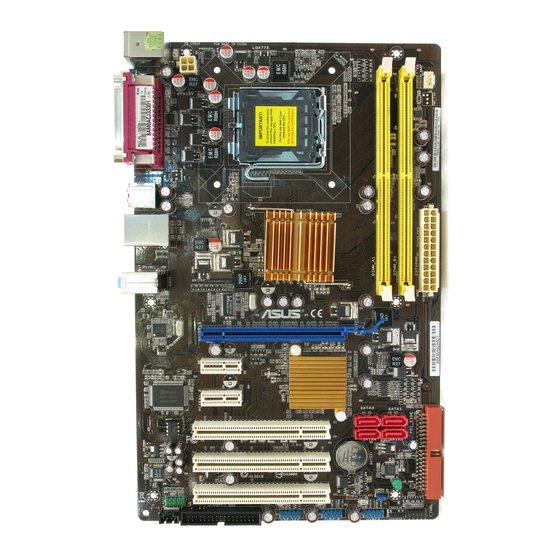
Page 15: Motherboard Layout
SATA3 SATA1 SATA4 SATA2 PCI1 BIOS P5QL SE Lithium Cell PCI2 CMOS Power SB_PWR PCI3 AAFP CLRTC SPDIF_OUT FLOPPY USB1112 USB910 USB78 F_PANEL SPEAKER Refer to 1.10.Connectors for more information about rear panel ports and internal connectors. ASUS P5QL SE... -
Page 16: Layout Contents
Contact your retailer immediately if the PnP cap is missing, or if you see any damage to the PnP cap/socket contacts/motherboard components. ASUS will shoulder the cost of repair only if the damage is shipment/ transit-related. -
Page 17: Installing The Cpu
To install a CPU: Locate the CPU socket on the motherboard. P5QL SE P5QL SE CPU socket 775 Before installing the CPU, ensure that the socket box is facing towards you and the load lever is on your left. Press the load lever with your thumb Retention.tab... - Page 18 Position the CPU over the socket, CPU.notch ensuring that the gold triangle is on the bottom-left corner of the socket then fit the socket alignment key into the CPU notch. Gold. triangle. mark Alignment.key Apply several drops of Thermal Interface Material to the exposed area of the CPU that the heatsink will be in contact with, ensuring that it is spread in an even thin...
-
Page 19: Installing The Cpu Heatsink And Fan
DO.NOT forget to connect the CPU_FAN CPU fan connector! Hardware CPU FAN PWM monitoring errors can occur if CPU FAN IN CPU FAN PWR you fail to plug this connector. P5QL SE P5QL SE CPU fan connector ASUS P5QL SE... -
Page 20: Uninstalling The Cpu Heatsink And Fan
Overview The motherboard comes with two Double Data Rate 2 (DDR2) Dual Inline Memory Modules (DIMM) sockets. The figure illustrates the location of the DDR2 DIMM sockets: P5QL SE P5QL SE 240-pin DDR2 DIMM sockets Channel Sockets Channel A DIMM_A1... -
Page 21: Memory Configurations
• For system stability, use a more efficient cooling system to support a full memory load (2 DIMMs) or overclocking conditions. P5QL SE Motherboard Qualified Vendors Lists (QVL) DDR2-1066MHz.capability DIMM.support. Chip. - Page 22 DDR2-800MHz.capability DIMM. Chip. support Vendor Part.No. Size .Chip.No. Brand Kingston KHX6400D2LL/1G Heat-Sink Package Kingston • • Kingston KHX6400D2LLK2/1GN 512MB Heat-Sink Package Kingston • • Kingston KVR800D2N5/512 512MB V59C1512804QCF25SY032406PECPA Promos • • Kingston KVR800D2N5/1G V59C1512804QCF25S0061904PECJA Promos • • Kingston KHX6400D2K2/2G 1G(Kit of 2) Heat-Sink Package Kingston •...
- Page 23 TMS51B264C081-805EP 512MB MS18T51280-2.5P0710 takeMS • • TAKEMS TMS1GB264C081-805EP MS18T51280-2.5P0716 takeMS • • ASINT SLY2128M8-JGE DDRII1208-GE 8115 ASINT • • ASINT SLZ2128M8-JGE DDRII1208-GE 8115 ASINT • • UMAX D48001GP3-63BJU U2S12D30TP-8E UMAX • UMAX D48002GP0-73BCU U2S24D30TP-8E UMAX • ASUS P5QL SE 1-13...
- Page 24 DDR2-667MHz.capability DIMM. Chip. support Vendor Part.No. Size .Chip.No. Brand Kingston KVR667D2N5/512 512MB HY5PS12821EFP-Y5 Hynix • • Kingston KVR667D2N5/1G HY5PS12821EFP-Y5 Hynix • • Kingston KVR667D2N5/2G 7RE22 D9HNL Micron • • SO1237650821 SBP D6408TR4CG Kingston KVR667D2N5/512 512MB Kingston • • L25USL074905PECNB Kingston KVR667D2N5/2G E1108ACBG-8E-E 0813A90CC Elpida...
-
Page 25: Installing A Dimm
•. B*: Supports one pair of modules inserted into the yellow slots as one pair of dual-channel memory configuration. Visit the ASUS website for the latest DDR2-1066/800/667MHz QVL. 1.7.3. Installing.a.DIMM Unplug the power supply before adding or removing DIMMs or other system components. -
Page 26: Removing A Dimm
A DDR2 DIMM is keyed with a notch so that it fits in only one direction. DO NOT force a DIMM into a socket to avoid damaging the DIMM. Firmly insert the DIMM into the socket until the retaining clips snap back in place and the DIMM is properly seated. -
Page 27: Configuring An Expansion Card
5-10 seconds, then move the cap back to pins 1-2. 3. Plug the power cord and turn ON the computer. 4. Hold down the <Del> key during the boot process and enter BIOS setup to re-enter data. ASUS P5QL SE 1-17... -
Page 28: Connectors
CLRTC P5QL SE Normal Clear RTC (Default) P5QL SE Clear RTC RAM 1.10. Connectors 1.10.1. Rear.panel.connectors PS/2.keyboard.port.(purple). This port is for a PS/2 keyboard. Parallel.port. This 25-pin port connects a parallel printer, a scanner, or other devices. - Page 29 USB 2.0 devices. Serial.port. This 9-pin COM1 port is for pointing devices or other serial devices. 10.. USB.2.0.ports.5.and.6. These two 4-pin Universal Serial Bus (USB) ports are available for connecting USB 2.0 devices. ASUS P5QL SE 1-19...
-
Page 30: Internal Connectors
P5QL SE NOTE:Orient the red markings on the floppy ribbon cable to PIN 1. P5QL SE Floppy disk drive connector Digital.audio.connector.(4-1.pin.SPDIF_OUT) This connector is for an additional Sony/Philips Digital Interface (S/PDIF) port. Connect an S/PDIF Out module cable to this connector, then install the module to a slot opening at the back of the system chassis. - Page 31 IDE ribbon cable to PIN 1. P5QL SE IDE connector Optical.drive.audio.connector.(4-pin.CD) These connectors allow you to receive stereo audio input from sound sources such as a CD-ROM, TV tuner, or MPEG card. P5QL SE P5QL SE Internal audio connector ASUS P5QL SE 1-21...
- Page 32 CPU fan connector! CPU_FAN CPU FAN PWM CPU FAN IN CPU FAN PWR P5QL SE P5QL SE CPU fan connector Only the CPU fan supports the ASUS Q-FAN feature. 1-22 Chapter 1: Product introduction...
- Page 33 AAFP P5QL SE P5QL SE Analog front panel connector • We recommend that you connect a high-definition front panel audio module to this connector to get the motherboard’s high-definition audio capability. • If you want to connect a high-definition front panel audio module to this connector, set the Front.Panel.Type item in the BIOS setup to [HD.Audio];.if you want to connect an...
- Page 34 SPEAKER P5QL SE PIN 1 P5QL SE Speaker Out Connector 10.. ATX.power.connectors.(24-pin.EATXPWR,.4-pin.EATX12V) These connectors are for ATX power supply plugs. The power supply plugs are designed to fit these connectors in only one orientation. Find the proper orientation and push down firmly until the connectors completely fit.
-
Page 35: System Panel Connector
PIN 1 P5QL SE HD_LED RESET P5QL SE System panel connector •. System.power.LED.(2-pin.PLED) This 2-pin connector is for the system power LED. Connect the chassis power LED cable to this connector. The system power LED lights up when you turn on the system power, and blinks when the system is in sleep mode. -
Page 36: Software.support
1.11. Software.support 1.11.1. Installing.an.operating.system This motherboard supports Windows XP/Vista Operating Systems (OS). Always install the ® latest OS version and corresponding updates to maximize the features of your hardware. • Motherboard settings and hardware options vary. Refer to your OS documentation for detailed information. -
Page 37: Chapter.2:.Bios.information
BIOS in the future. Copy the original motherboard BIOS using the ASUS Update or AFUDOS utilities. 2.1.1. ASUS.Update.utility The ASUS Update is a utility that allows you to manage, save, and update the motherboard BIOS in Windows environment. The ASUS Update utility allows you to: ®... - Page 38 Updating.the.BIOS.through.the.Internet To update the BIOS through the Internet: Launch the ASUS Update utility from the Windows desktop by clicking Start.>. ® Programs.>.ASUS.>.ASUSUpdate.>.ASUSUpdate. The ASUS Update main window appears. Select Update.BIOS from.the. Select the ASUS FTP site nearest you Internet from the drop-down menu, to avoid network traffic, or click Auto.
-
Page 39: Creating A Bootable Floppy Disk
2.1.3. ASUS.EZ.Flash.2.utility The ASUS EZ Flash 2 feature allows you to update the BIOS without having to go through the long process of booting from a floppy disk and using a DOS-based utility. The EZ Flash 2 utility is built in the BIOS chip so it is accessible by pressing <Alt>.+.<F2> during the Power-On Self-Test (POST). -
Page 40: Afudos Utility
ASUSTek EZ Flash 2 BIOS ROM Utility V3.25 FLASH TYPE: MXIC 25L8005 Current ROM Update ROM BOARD: P5QL SE BOARD: Unknown VER: 0302 (H:00 B:02) VER: Unknown DATE: 09/09/2008 DATE: Unknown PATH: A:\ Note [Enter] Select or Load [Tab] Switch [V] Drive Info [Up/Down/Home/End] Move [B] Backup [ESC] Exit... - Page 41 Updating the BIOS file To update the BIOS file using the AFUDOS utility: Visit the ASUS website at www.asus.com to download the latest BIOS file for this motherboard. Save the BIOS file to a bootable floppy disk. We recommend that you write the BIOS filename on a piece of paper; you will need to key in the exact BIOS filename at the DOS prompt later.
-
Page 42: Asus Crashfree Bios 3 Utility
2.1.5. ASUS.CrashFree.BIOS.3.utility The ASUS CrashFree BIOS 3 is an auto recovery tool that allows you to restore the BIOS file when it fails or gets corrupted during the update process. You can update a corrupted BIOS file using the motherboard Support DVD, a floppy disk, or USB flash disk that contains the updated BIOS file. - Page 43 BIOS file. Restart the system after the utility completes the update process. • Only the USB flash disk with FAT 32/16 format and single partition supports ASUS CrashFree BIOS 3. The device size should be smaller than 8GB.
-
Page 44: Bios.setup.program
• The BIOS setup screens in this section are for reference only. They may not exactly match what you see on your screen. • Visit the ASUS website at www.asus.com to download the latest BIOS file for this motherboard. Chapter 2: BIOS setup... -
Page 45: Bios Menu Screen
At the bottom right corner of a menu screen are the navigation keys for that particular menu. Use the navigation keys to select items in the menu and change the settings. Some of the navigation keys differ from one screen to another. ASUS P5QL SE... -
Page 46: Menu Items
2.2.4. Menu.items BIOS SETUP UTILITY Main Advanced Power Boot Tools Exit The highlighted item on Use [ENTER], [TAB] or System Time [14:14:35] [SHIFT-TAB] to select the menu bar displays the System Date [Wed 04/16/2008] a field. Legacy Diskette A [1.44M, 3.5 in] specific items for that menu. -
Page 47: Main.menu
IDE device type. Select [CDROM] if you are specifically configuring a CD-ROM drive. Select [ARMD] (ATAPI Removable Media Device) if your device is either a ZIP, LS-120, or MO drive. Configuration options: [Not Installed] [Auto] [CDROM] [ARMD] ASUS P5QL SE 2-11... -
Page 48: Storage Configuration
LBA/Large.Mode.[Auto] Enables or disables the LBA mode. Setting to [Auto] enables the LBA mode if the device supports this mode, and if the device was not previously formatted with LBA mode disabled. Configuration options: [Disabled] [Auto] Block.(Multi-sector.Transfer).M.[Auto] Enables or disables data multi-sectors transfers. When set to [Auto], the data transfer from and to the device occurs multiple sectors at a time if the device supports multi-sector transfer feature. -
Page 49: System Information
Select any one of the preset overclocking configuration options: [MANUAL].- allows you to manually set overclocking parameters. [Auto].- loads the optimal settings for the system. [Overclock Profile] - loads overclocking profiles with optimal parameters for stability when overclocking. ASUS P5QL SE 2-13... - Page 50 The follow items appear only when you set the Ai.Overclocking item to [Manual]. CPU.Frequency.[xxx] Displays the frequency sent by the clock generator to the system bus and PCI bus. Use the <+> and <-> keys to adjust the CPU frequency. You can also type the desired CPU frequency using the numeric keypad.
- Page 51 Setting a very high voltage may damage the component permanently, while setting a very low voltage may cause the system to become unstable. NB.Voltage.[Auto] Allows you to set the Northbridge voltage. Configuration options: [Auto] [1.129V] [1.199V] [1.269V] [1.339V] ASUS P5QL SE 2-15...
-
Page 52: Cpu Configuration
2.4.2 CPU Configuration The items in this menu show the CPU-related information that the BIOS automatically detects. Ratio.CMOS.Setting.[Auto] Sets the ration between CPU core clock and the FSB frequency. Configuration options: [Auto] • If an invalid ratio is set in CMOS, then the actual and set values may differ. •... -
Page 53: Chipset
Allows you to enable or disable the JMB368 controller. Configuration options: [Enabled] [Disabled] Serial.Port1.Address.[3F8/IRQ4] Allows you to select the Serial Port1 base address. Configuration options: [Disabled] [3F8/IRQ4] [2F8/IRQ3] [3E8/IRQ4] [2E8/IRQ3] Parallel.Port.Address.[378] Allows you to select the Parallel Port base addresses. Configuration options: [Disabled] [378] [278] [3BC] ASUS P5QL SE 2-17... -
Page 54: Usb Configuration
Parallel.Port.Mode.[ECP] Allows you to select the Parallel Port mode. Configuration options: [Normal] [Bi-Directional] [EPP] [ECP] ECP Mode DMA Channel [DMA3] Appears only when the Parallel Port Mode is set to [ECP]. This item allows you to set the Parallel Port ECP DMA. Configuration options: [DMA0] [DMA1] [DMA3] Parallel Port IRQ [IRQ7] Allows you to select parallel port IRQ. -
Page 55: Power.menu
Allows you to use the PS/2 keyboard/mouse to generate a wake event. This feature requires an ATX power supply that provides at least 1A on the +5VSB lead. Configuration options: [Disabled] [Enabled] Resume.On.Ring.[Disabled] Allows you to enable or disable RI to generate a wake event. Configuration options: [Disabled] [Enabled] ASUS P5QL SE 2-19... -
Page 56: Hardware Monitor
Resume.On.PCI.Devices.[Disabled] When set to [Enabled], this parameter allows you to wake the system through a PCI LAN or modem card. This feature requires an ATX power supply that provides at least 1A on the +5VSB lead. Configuration options: [Disabled] [Enabled] Resume.On.PCIE.Devices.[Disabled] When set to [Enabled], this parameter allows you to wake the system through a PCI Express card. -
Page 57: Boot.menu
POST items. Configuration options: [Disabled] [Enabled] Full.Screen.Logo.[Enabled] This allows you to enable or disable the full screen logo display feature. Configuration options: [Disabled] [Enabled] Set this item to [Enabled] to use the ASUS MyLogo2 feature. ™ AddOn.ROM.Display.Mode.[Force.BIOS] Sets the display mode for option ROM. Configuration options: [Force BIOS] [Keep Current] Bootup.Num-Lock.[On]... -
Page 58: Security
2.6.3. Security The Security menu items allow you to change the system security settings. Select an item then press <Enter> to display the configuration options. Change.Supervisor.Password Select this item to set or change the supervisor password. The Supervisor.Password item on top of the screen shows the default Not.Installed. After you set a password, this item shows Installed. -
Page 59: Tools.menu
2.7.1. ASUS.EZ.Flash.2 Allows you to run ASUS EZ Flash 2. When you press <Enter>, a confirmation message appears. Use the left/right arrow key to select between [Yes] or [No], then press <Enter> to confirm your choice. See section 2.1.3.ASUS.EZ.Flash.2.utility for details. -
Page 60: Exit.menu
2.8. Exit.menu The Exit menu items allow you to load the optimal or failsafe default values for the BIOS items, and save or discard your changes to the BIOS items. BIOS SETUP UTILITY Main Advanced Power Boot Tools Exit Exit Options Exit system setup after saving the Exit &...