Table of Contents
Advertisement
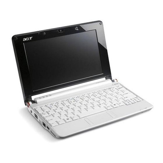
Acer Aspire One AOA150-1570 Disassembly
Model
The Acer Aspire One AOA150-1570 is the model with the 120GB hard drive (not the Flash drive) and
1GB RAM with Windows XP.
Disassembly
Beware of the ESD (ElectroStatic Discharge) hazard. Wear a grounding wrist strap.
Remove the battery.
Remove the 6 screws from the bottom of the case. There are 3 across the front and 3 in the battery
compartment.
Pry up the 2 rear rubber feet and remove the 2 screws underneath them. Stick the feet to the battery for
safekeeping.
Bottom of machine with locations of screws marked
Note: The 3 short screws go in the battery compartment.
Advertisement
Table of Contents

Summary of Contents for Acer Aspire One AOA150
- Page 1 Acer Aspire One AOA150-1570 Disassembly Model The Acer Aspire One AOA150-1570 is the model with the 120GB hard drive (not the Flash drive) and 1GB RAM with Windows XP. Disassembly Beware of the ESD (ElectroStatic Discharge) hazard. Wear a grounding wrist strap.
- Page 2 Remove the keyboard. There are 3 locking tabs at the top of the keyboard, in the top cover, sticking out over the edge of the keyboard. Press them toward the back of the machine with a small flat screwdriver. Gently pry the keyboard up from the top. Be careful not to pop off any keycaps. There are small nibs holding it in place on the sides, and they will resist removal.
- Page 3 When the keyboard comes up, disconnect the keyboard cable by gently pulling up on the right edge of the black cable lock (near the blue part of the cable). When it rotates up, the cable can be pulled free. Lift out the keyboard. Keyboard cable connector...
- Page 4 Disconnect the touchpad cable, which is a smaller version of the keyboard connector, by lifting the black lock mechanism. Touchpad cable connector...
- Page 5 Remove the 6 screws holding the top cover down. Keep track of which screws go where. There are some different sizes. Screw locations in top cover. There are also locking tabs around the edge of the top cover. You will have to pry it up to get it started. Remove the top cover by tilting up the touchpad end and pulling it toward you.
- Page 6 Again, take note of which screws go where. Remove the 1 screw holding the wireless card (the small board in the front). Tilt the wireless card up and remove it from its socket. You do not need to disconnect the antenna wires. Remove the 1 screw holding the mainboard (the large board on the left).
- Page 7 Lift the I/O card and the WIFI card out of the way. Lift the front edge of the mainboard and pull it toward you to get it out from under the left rear tab (under the LCD cable). The hard drive will come with it. You can leave the LCD cable in place (the wide ribbon at the left rear).
- Page 8 The 120GB SATA hard drive is attached to the mainboard with 2 screws. It is also enclosed in a shell attached with 4 screws. Hard drive enclosure with attaching screws, and RAM socket If you are changing the hard drive, remove the 2 screws holding the enclosure in place, and then pull the drive from the SATA socket.
- Page 9 Just for Information The RAM looks like this. You can zoom in to 200% to see the details (the image is higher resolution than it appears here). The RAM stick...
- Page 10 The Hard Drive looks like this. You can zoom in to 200% to see the details (the image is higher resolution than it appears here). The hard drive and its enclosure...
- Page 11 Reassembly Assembly is the exact reverse of the disassembly procedure, but with a couple of cautions. When you replace the mainboard be sure to slip it UNDER the clip at the left rear under the LCD cable. Metal clip over mainboard, and LCD cable Once the mainboard is in place, tuck the LCD cable back down into its spot.
- Page 12 When reinstalling the I/O board, carefully align the WIFI switch to sit in the switch extender. WIFI switch (white tab) sitting in switch extender (black channel) When replacing the top cover, tilt the back down so it will slip under the LCD hinges. Lower the front into place.


