Table of Contents
Advertisement
Advertisement
Table of Contents

Related Manuals for Gigabyte GA-A75M-S2V


Summary of Contents for Gigabyte GA-A75M-S2V
- Page 1 GA-A75M-S2V User's Manual Rev. 1003 12ME-A75MS2V-1003R...
-
Page 3: Identifying Motherboard Revision
The trademarks mentioned in this manual are legally registered to their respective owners. Disclaimer Information in this manual is protected by copyright laws and is the property of GIGABYTE. Changes to the specifications and features in this manual may be made by GIGABYTE with- out prior notice. -
Page 4: Table Of Contents
Table of Contents GA-A75M-S2V Motherboard Layout ................5 GA-A75M-S2V Motherboard Block Diagram ..............6 Chapter 1 Hardware Installation ..................7 Installation Precautions ................... 7 Product Specifications ..................8 Installing the APU ...................11 Installing the Memory ..................12 Installing an Expansion Card ................. 12 Setup of the AMD Dual Graphics Configuration ........... -
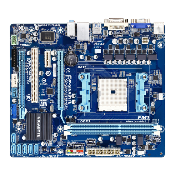
Page 5: Ga-A75M-S2V Motherboard Layout
GA-A75M-S2V Motherboard Layout KB_MS_USB CPU_FAN ATX_12V SYS_FAN Socket FM1 R_USB30 Realtek USB_LAN RTL8111E AUDIO GA-A75M-S2V PCIEX16 M_BIOS PCIEX1 B_BIOS SATA3_5 SATA3_4 PCIEX4 CODEC SATA3_3 SATA3_2 F_AUDIO SATA3_0 SATA3_1 F_USB30 F_USB Box Contents GA-A75M-S2V motherboard Motherboard driver disk Two SATA cables... -
Page 6: Ga-A75M-S2V Motherboard Block Diagram
GA-A75M-S2V Motherboard Block Diagram 1 PCI Express x16 APU CLK+/- (100 MHz) DISP CLK+/- (100 MHz) 1 PCI Express x1 DDR3 2400(O.C.)/1866/ RJ45 AMD APU PCIe CLK 1600/1333/1066 MHz (100 MHz) Realtek Dual Channel Memory RTL8111E DVI-D PCI Express Bus... -
Page 7: Chapter 1 Hardware Installation
Chapter 1 Hardware Installation Installation Precautions The motherboard contains numerous delicate electronic circuits and components which can become damaged as a result of electrostatic discharge (ESD). Prior to installation, carefully read the user's manual and follow these procedures: • Prior to installation, do not remove or break motherboard S/N (Serial Number) sticker or warranty sticker provided by your dealer. -
Page 8: Product Specifications
4 GB. Dual channel memory architecture Š Support for DDR3 2400 (O.C.)/1866/1600/1333/1066 MHz memory modules Š (Go to GIGABYTE's website for the latest supported memory speeds and memory modules.) Onboard APU: Š... - Page 9 Internal 1 x 24-pin ATX main power connector Š Connectors 1 x 4-pin ATX 12V power connector Š 6 x SATA 6Gb/s connectors Š 1 x APU fan header Š 1 x system fan header Š 1 x front panel header Š...
- Page 10 Support for Microsoft Windows 7/Vista/XP Š ® System Form Factor Micro ATX Form Factor; 24.4cm x 21.0cm Š * GIGABYTE reserves the right to make any changes to the product specifications and product-related information without prior notice. Hardware Installation - 10 -...
-
Page 11: Installing The Apu
Read the following guidelines before you begin to install the APU: • Make sure that the motherboard supports the APU. (Go to GIGABYTE's website for the latest APU support list.) • Always turn off the computer and unplug the power cord from the power outlet before installing the APU to prevent hardware damage. -
Page 12: Installing The Memory
• Make sure that the motherboard supports the memory. It is recommended that memory of the same capacity, brand, speed, and chips be used. (Go to GIGABYTE's website for the latest supported memory speeds and memory modules.) • Always turn off the computer and unplug the power cord from the power outlet before installing the memory to prevent hardware damage. -
Page 13: Setup Of The Amd Dual Graphics Configuration
1-6 Setup of the AMD Dual Graphics Configuration Combining the onboard GPU with a discrete graphics card, AMD's Dual Graphics technology can provide significantly advanced display performance for AMD platform. Read the following instructions on configuring a Dual Graphics system. A. System Requirements - AMD A series processor - Windows 7 operating system - An AMD Dual Graphics technology-supported motherboard and correct driver - An AMD Radeon HD 6000 series graphics card that supports AMD Dual Graphics technology (for more... -
Page 14: Back Panel Connectors
Back Panel Connectors USB 2.0/1.1 Port The USB port supports the USB 2.0/1.1 specification. Use this port for USB devices such as a USB key- board/mouse, USB printer, USB flash drive and etc. PS/2 Keyboard/Mouse Port Use this port to connect a PS/2 mouse or keyboard. D-Sub Port (Note 1) The D-Sub port supports a 15-pin D-Sub connector. -
Page 15: Internal Connectors
Line Out Jack (Green) The default line out jack. Use this audio jack for a headphone or 2-channel speaker. This jack can be used to connect front speakers in a 4/5.1/7.1-channel audio configuration. Mic In Jack (Pink) The default Mic in jack. Microphones must be connected to this jack. To enable 7.1-channel audio, you have to use an HD front panel audio module and enable the multi-channel audio feature through the audio driver. - Page 16 1/2) ATX_12V/ATX (2x2 12V Power Connector and 2x12 Main Power Connector) With the use of the power connector, the power supply can supply enough stable power to all the com- ponents on the motherboard. Before connecting the power connector, first make sure the power supply is turned off and all devices are properly installed. The power connector possesses a foolproof design. Connect the power supply cable to the power connector in the correct orientation.
- Page 17 3/4) CPU_FAN/SYS_FAN (Fan Headers) The motherboard has a 4-pin APU fan header (CPU_FAN) and a 4-pin system fan header (SYS_FAN). Each fan header supplies a +12V power voltage and possesses a foolproof insertion design. When con- necting a fan cable, be sure to connect it in the correct orientation. Most fans are designed with color- coded power connector wires.
-
Page 18: Front Panel Header
6) F_PANEL (Front Panel Header) Connect the power switch, reset switch, speaker, chassis intrusion switch/sensor and system status indicator on the chassis to this header according to the pin assignments below. Note the positive and negative pins before connecting the cables. SPEAK- PWR- Power LED Speaker PWR+... - Page 19 7) F_AUDIO (Front Panel Audio Header) The front panel audio header supports Intel High Definition audio (HD) and AC'97 audio. You may connect your chassis front panel audio module to this header. Make sure the wire assignments of the module con- nector match the pin assignments of the motherboard header. Incorrect connection between the module connector and the motherboard header will make the device unable to work or even damage it.
- Page 20 9) F_USB (USB 2.0/1.1 Header) The header conforms to USB 2.0/1.1 specification and can provide two USB ports via an optional USB bracket. For purchasing the optional USB bracket, please contact the local dealer. Pin No. Definition Power (5V) Power (5V) USB DX- USB DY- USB DX+ USB DY+...
-
Page 21: Clear Cmos Jumper
11) COM (Serial Port Header) The COM header can provide one serial port via an optional COM port cable. For purchasing the op- tional COM port cable, please contact the local dealer. Pin No. Definition NDCD- NSIN NSOUT NDTR- NDSR- NRTS- NCTS- NRI- No Pin 12) CLR_CMOS (Clearing CMOS Jumper) Use this jumper to clear the CMOS values (e.g. - Page 22 13) BAT (Battery) The battery provides power to keep the values (such as BIOS configurations, date, and time information) in the CMOS when the computer is turned off. Replace the battery when the battery voltage drops to a low level, or the CMOS values may not be accurate or may be lost. You may clear the CMOS values by removing the battery: 1.
-
Page 23: Chapter 2 Bios Setup
To see more advanced BIOS Setup menu options, you can press <Ctrl> + <F1> in the main menu of the BIOS Setup program. To upgrade the BIOS, use either the GIGABYTE Q-Flash or @BIOS utility. Q-Flash allows the user to quickly and easily upgrade or back up BIOS without entering the operating •... -
Page 24: The Main Menu
The Main Menu Once you enter the BIOS Setup program, the Main Menu (as shown below) appears on the screen. Use ar- row keys to move among the items and press <Enter> to accept or enter a sub-menu. (Sample BIOS Version: F1e) CMOS Setup Utility-Copyright (C) 1984-2011 Award Software MB Intelligent Tweaker(M.I.T.) Load Fail-Safe Defaults ... -
Page 25: Mb Intelligent Tweaker(M.i.t.)
2-3 MB Intelligent Tweaker(M.I.T.) CMOS Setup Utility-Copyright (C) 1984-2011 Award Software MB Intelligent Tweaker(M.I.T.) Item Help IGX Configuration [Press Enter] Menu Level CPU Clock Ratio [Auto] 2300Mhz CPU NorthBridge Freq. [Auto] Core Performance Boost [Enabled] (Note) CPB Ratio [Auto] 2400Mhz (Note) CPU Host Clock Control [Auto] x CPU Frequency (MHz) PCIe Spread Spectrum [Disabled] Set Memory Clock... - Page 26 CPU Clock Ratio Allows you to alter the clock ratio for the installed CPU. The adjustable range is dependent on the CPU being installed. CPU NorthBridge Freq. Allows you to alter the frequency of the CPU North Bridge controller. Core Performance Boost (Note) Allows you to determine whether to enable the Core Performance Boost (CPB) technology, a CPU performance-boost technology.
- Page 27 DRAM Configuration CMOS Setup Utility-Copyright (C) 1984-2011 Award Software DRAM Configuration Item Help DDR3 Timing Items [Auto] SPD Auto Menu Level x 1T/2T Command Timing Auto x CAS# latency Auto x RAS to CAS R/W Delay Auto x Row Precharge Time Auto x Minimum RAS Active Time Auto x TwTr Command Delay Auto...
- Page 28 Four Bank Activate Window Options are: Auto (default), 16T~40T. Bank Interleaving Enables or disables memory bank interleaving. Enabled allows the system to simultaneously access dif- ferent banks of the memory to increase memory performance and stability. (Default: Enabled) ******** System Voltage Optimized ******** System Voltage Control Determines whether to manually set the system voltages.
-
Page 29: Standard Cmos Features
2-4 Standard CMOS Features CMOS Setup Utility-Copyright (C) 1984-2011 Award Software Standard CMOS Features Item Help Date (mm:dd:yy) Thu, Jun 9 2011 Menu Level Time (hh:mm:ss) 22:31:24 IDE Channel 0 Master [None] IDE Channel 0 Slave [None] IDE Channel 1 Master [None] IDE Channel 1 Slave [None] IDE Channel 2 Master [None] IDE Channel 3 Master [None] Halt On... -
Page 30: Advanced Bios Features
2-5 Advanced BIOS Features CMOS Setup Utility-Copyright (C) 1984-2011 Award Software Advanced BIOS Features Item Help IGX Configuration [Press Enter] Menu Level Virtualization [Disabled] AMD K8 Cool&Quiet control [Auto] Hard Disk Boot Priority [Press Enter] EFI CD/DVD Boot Option [Auto] First Boot Device [Hard Disk] Second Boot Device [CDROM] Third Boot Device [USB-HDD] Password Check [Setup] HDD S.M.A.R.T. Capability [Disabled] Away Mode [Disabled] Full Screen LOGO Show [Enabled] Init Display First... -
Page 31: Integrated Peripherals
(Default: Disabled) Full Screen LOGO Show Allows you to determine whether to display the GIGABYTE Logo at system startup. Disabled displays normal POST message. (Default: Enabled) Init Display First Specifies the first initiation of the monitor display from the installed PCI graphics card, PCI Express graphics card, or the onboard graphics. - Page 32 OnChip SATA Port4/5 Type (SATA3_4 and SATA3_5 connectors) This option is configurable only when OnChip SATA Type is set to RAID or AHCI. Configures the oper- ating mode of the SATA3_4 and SATA3_5 connectors. Disables RAID for the SATA controller and configures the SATA controller to PATA mode. (Default) As SATA Type The mode depends on the OnChip SATA Type settings.
-
Page 33: Power Management Setup
Onboard Audio Function Enables or disables the onboard audio function. (Default: Enabled) If you wish to install a 3rd party add-in audio card instead of using the onboard audio, set this item to Disabled. USB Controllers Enables or disables the integrated USB controllers. (Default: Enabled) Disabled will turn off all of the USB functionalities below. - Page 34 PME Event Wake Up Allows the system to be awakened from an ACPI sleep state by a wake-up signal from a PCI or PCIe de- vice. Note: To use this function, you need an ATX power supply providing at least 1A on the +5VSB lead. (Default: Enabled) HPET Support (Note)
-
Page 35: Pc Health Status
PC Health Status CMOS Setup Utility-Copyright (C) 1984-2011 Award Software PC Health Status Item Help Reset Case Open Status [Disabled] Menu Level Case Opened Vcore 1.364V DDR3 1.5V 1.536V +3.3V 3.280V +12V 12.048V Current System Temperature Current CPU Temperature Current CPU FAN Speed 1962 RPM Current SYSTEM FAN Speed 0 RPM... -
Page 36: Load Fail-Safe Defaults
CPU Smart FAN Mode Specifies how to control CPU fan speed. This item is configurable only if CPU Smart FAN Control is set to Enabled. Auto Lets the BIOS automatically detect the type of CPU fan installed and sets the optimal CPU fan control mode. (Default) Voltage Sets Voltage mode for a 3-pin CPU fan. -
Page 37: Set Supervisor/User Password
2-11 Set Supervisor/User Password CMOS Setup Utility-Copyright (C) 1984-2011 Award Software MB Intelligent Tweaker(M.I.T.) Load Fail-Safe Defaults Standard CMOS Features Load Optimized Defaults Advanced BIOS Features Set Supervisor Password Integrated Peripherals Set User Password Power Management Setup Save &... -
Page 38: Save & Exit Setup
2-12 Save & Exit Setup CMOS Setup Utility-Copyright (C) 1984-2011 Award Software MB Intelligent Tweaker(M.I.T.) Load Fail-Safe Defaults Standard CMOS Features Load Optimized Defaults Save to CMOS and EXIT (Y/N)? Y Advanced BIOS Features Set Supervisor Password Integrated Peripherals Set User Password ... -
Page 39: Chapter 3 Drivers Installation
Chapter 3 Drivers Installation • Before installing the drivers, first install the operating system. • After installing the operating system, insert the motherboard driver disk into your optical drive. The driver Autorun screen is automatically displayed which looks like that shown in the screen shot below. - Page 40 Steps: 1. Turn on your computer and press <Delete> to enter BIOS Setup during the POST (Power-On Self-Test). Make sure OnChip SATA Controller is enabled. To enable RAID for the SATA3_0/1/2/3 connectors, set OnChip SATA Type to RAID. To enable RAID for the SATA3_4/SATA3_5 connectors, set OnChip SATA Type to RAID and set OnChip SATA Port4/5 Type to As SATA Type.
-
Page 41: Regulatory Statements
Contravention will be prosecuted. We believe that the information contained herein was accurate in all respects at the time of printing. GIGABYTE cannot, however, assume any responsibility for errors or omissions in this text. Also note that the informa- tion in this document is subject to change without notice and should not be construed as a commitment by GIGABYTE. - Page 42 Appendix - 42 -...
- Page 43 - 43 - Appendix...
- Page 44 WEB address (English): http://www.gigabyte.com WEB address (Chinese): http://www.gigabyte.tw You may go to the GIGABYTE website, select your language in the language list on the top right corner of the website. • GIGABYTE Global Service System To submit a technical or non-technical (Sales/Market- ing) question, please link to: http://ggts.gigabyte.com.tw...