Panasonic AW-RP505 Operating Instructions Manual
Multi hybrid control panel
Hide thumbs
Also See for AW-RP505:
- Operating instructions manual (40 pages) ,
- Service manual (36 pages)
Table of Contents
Advertisement
Quick Links
Download this manual
See also:
Service Manual
Advertisement
Table of Contents

Related Manuals for Panasonic AW-RP505


Summary of Contents for Panasonic AW-RP505
- Page 1 Multi Hybrid Control Panel AW-RP505 Before attempting to connect or operate this product, please read these instructions completely.
- Page 2 For U.S.A CAUTION Warning: RISK OF ELECTRIC SHOCK Do not install this product near any object that burns easily. DO NOT OPEN In case of using a halogen lamp, installation of it near such an object could cause a fire due to the heat generated by the lamp.
-
Page 3: Table Of Contents
CONTENTS FEATURES ......................................2 PRECAUTIONS ....................................3 MAJOR OPERATING CONTROLS AND THEIR FUNCTIONS ......................4 INSTALLATION OF PAN/TILT HEAD ..............................19 CONNECTIONS ....................................22 OPERATING PROCEDURES ................................26 RACK MOUNTING ..................................... 34 SPECIFICATIONS ....................................36 ACCESSORIES ....................................37... -
Page 4: Features
FEATURES • The Multi Hybrid Control Panel AW-RP505 is combined • The maximum cable length from this control panel to with the Multiport Hub (AW-HB505) to control up to five the Multiport Hub is 10 meters. The maximum cable Pan/tilt Heads (AW-PH300) and Color Video Cameras length between the multiport hub and the cameras and (AW-E560). -
Page 5: Precautions
PRECAUTIONS • Use only with AC Adaptor AW-PS301. • Care Pull out the power cable plug, and wipe the control • Handle the control panel with care. panel clean with a dry cloth. If it is extremely dirty, dip Dropping the control panel or subjecting it to a strong a cloth into a diluted solution of kitchen detergent, shock can cause a failure or an accident. -
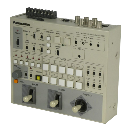
Page 6: Major Operating Controls And Their Functions
MAJOR OPERATING CONTROLS AND THEIR FUNCTIONS Control Panel Note: To control the cameras and M u l t i H y b r i d C o n t r o l P a n e l A W - R P 5 0 5 G / L P H A S E G A I N AUTO/ATW... - Page 7 q Power Indicator [POWER] control panel are sent to the selected camera to Lights red when POWER ON/OFF Switch w is in the update its settings. Do not shift CAM CONT Switch r to the ON position except when changing the ON position, and goes out when the same switch is set camera settings.
- Page 8 u Gain Selection Switch [GAIN, HIGH/MID/LOW] !0 White Balance Ach Selection Switch This switch is valid only when GAIN AGC/MANU [AUTO/ATW, A] Switch y is in the MANU position. Select a camera When this switch is pressed, white balance will be as with CONTROL Switch @2 , set CAM CONT Switch r to stored in Channel A of the camera selected with CON- TROL Switch @2 .
- Page 9 !6 Genlock Phase Control Switch Note: White balance may not be adjustable if there is no white in the image being taken by the camera. [G/L PHASE, ON/OFF] For details, refer to the Operating Instructions for Used to adjust the genlock phase in operating the the Camera.
- Page 10 Switch @2 , set CAM CONT Switch r to the ON posi- adjustment range of over 360°. Before making an adjustment, set CAM CONT Switch r and G/L PHASE tion, then adjust the total pedestal level with T.PED Switch !6 to the ON position. After the adjustment, set Control @0 0 .
- Page 11 Set the switch to the MANU position in storing iris data Caution: In connecting a halogen lamp to the Pan/tilt in PRESET Switch @8 with MEMORY Switch @7 . If the Head AC Adaptor (AW-PS300), make sure that it is switch is in the AUTO position, iris data will not be in the wattage range of 250 to 500W.
- Page 12 To preset them in these buttons, first select a camera at low speed, provided that SPEED SW CHANGE and pan/tilt head with CONTROL Switch @2 2 , then select Switch $9 is in the LOW position. If one of these levers is moved with SPEED Switch @9 depressed when a head pan/tilt position, lens zoom/focus/iris, or cam- SPEED SW CHANGE Switch $9 is in the HIGH position,...
- Page 13 #5 Option Switch [OP, ON/OFF] Note: At the same time as a pan/tilt head is selected with CONTROL Switch @2 2 , the heater or fan of the Controls the option switch terminal on the pan/tilt head selected pan/tilt head is switched on or off AC adapter (AW-PS300) to short circuit or open it.
- Page 14 #7 Focus Lever [FOCUS FAR/NEAR] Note: TILT REVERSE Switch %3 and PAN REVERSE Switch %4 may be used to reverse the operating Used to adjust the focus of the lens that is connected to the pan/tilt head selected with CONTROL Switch @2 2 . direction of the pan/tilt head, but be sure to set the Used to adjust the lens focus at varying speed operating direction of the pan/tilt head with its...
-
Page 15: Rear Panel
REAR PANEL G / L I N PREVIEW MONITOR OUT D C 1 2 V I N M U L T I P O R T H U B AUX CONTROL IN T A L L Y P A N / T I L T C A M E R A CONTROL CONTROL OUT... - Page 16 Ground 8-pin DIN connector pin assignment (as viewed from the rear of the control panel) Zoom Focus Tilt control control control control Example of auxillary control circuit 6.8K ZOOM Iris control FOCUS TILT 6.8K SPEED switch SPEED IRIS Note: Make sure that the lens and pan/tilt head stop Ground GND at the center point of the zoom, focus, pan and tilt controls (or at the lever reset position if the controls have a lever reset function).
- Page 17 $7 Preview Video Output Connector [PREVIEW MONITOR OUT] (BNC Connector) The video signals of the camera selected with CON- TROL Switch @2 are output from this connector so that the selected camera can be visually confirmed. Connect this connector to the monitor video input with a coaxial cable.
-
Page 18: Front Panel
Front Panel T I LT PA N S P E E D . S W Z O O M Z O O M / F O C U S F O C U S R E V E R S E R E V E R S E C H A N G E R E V E R S E... - Page 19 %3 Tilt Reverse Switch [TILT REVERSE, NOR/REV] REV position, the operating directions shown on the panel are reversed. In this case, paste the supplied Changes the tilt direction controlled by PAN/TILT Lever #8 . The pan/tilt head turns up when PAN/TILT Lever #8 seal on the panel.
- Page 20 Note: TILT REVERSE Switch %3 and PAN REVERSE Switch %4 may be used to reverse the operating direction of the pan/tilt head, but be sure to set the operating direction of the pan/tilt head with its mounting direction selection switch during its installation depending on whether the pan/tilt head is mounted on the floor or is suspended.
-
Page 21: Installation Of Pan/Tilt Head
INSTALLATION OF PAN/TILT HEAD • Install the pan/tilt head after carefully reading the Have a strong enough wire rod head and fasten it Operating Instructions for Pan/tilt Head. securely to a firm board, such as of the ceiling. • Have four hex bolts (M6 x 4) ready for mounting the pan/title head. - Page 22 e Place the cover back on the pan/tilt head. • Changing Switch Settings on Pan/tilt Head q Remove the cover from the pan/tilt head. * Be sure not to trap the wires. * Be careful of the Tally Indicator wire. Tally Indicator DESKTOP SW 1...
- Page 23 • Shifting Cable Compensation Switch on Pan/tilt • How to Mount the Lens Head If the distance from the control panel to the pan/tilt • Turn the lens lock ring knob fully counterclockwise. head is longer than 300 meters, set the cable compen- sation switch to the ON position by observing the fol- •...
-
Page 24: Connections
CONNECTIONS • Before making any connection, switch off all the com- • Use the Multiport Hub AW-HB505, the Pan/tilt Head ponents of the system. AW-PH300 and the Color Video Camera AW-E560. (The Color Video Camera WV-E550 cannot be used.) • Use the Control Panel AC Adaptor AW-PS301 (option- To connect the pan/tilt head to the camera, the Camera al), Multiport Hub AC Adaptor AW-PS505 (optional) and Cable AW-CA20T15 (optional) is necessary. - Page 25 • Connect the iris control cable of the motor-driven zoom • Connect the control panel to the multiport hub with the lens to the camera and the remote (zoom/focus control) three coaxial cables (video signal, G/L signal, camera cable to the pan/tilt head. If the remote (zoom/focus control signal) and one 10BASE-T straight cable control) cable of the motor-driven zoom lens is con-...
- Page 26 To Servo Control Zoom Lens IRIS CONTROL Color Video Camera AW-E560 Pan/tilt Head PAGE ITEM DOWN AW-PH300 IRIS (AWC) (ABC) (BAR) G/L IN VIDEO OUT PREVIEW OUT ZOOM/FOCUS VBS/HD G/L THROUGH OUT VIDEO/RGB REMOTE CONTROL G/L IN CAUTION ZOOM/FOCUS EXT DC IN SEE MANUAL CONTROL G / L I N...
- Page 27 • Example of System Configuration POWER POWER PUSH PUSH 1470 Color Monitor WV-CM 1470 Color Monitor WV-CM POWER PUSH Color Monitor WV-CM 1470 POWER PUSH Color Monitor WV-CM 1470 ZOOM/FOCUS CONTROL Color Camera IRIS CONTROL Color Monitor WV-E550A (75 terminator) AW-E560 Camera Cable AW-CA20T15...
-
Page 28: Operating Procedures
OPERATING PROCEDURES 1.Power Up tilting limiter Preset position selection switch Press the power switch on each pan/tilt head AC adapter and the power switch on the multiport hub AC Left panning Lights on limiter completion adapter to the ON position, then press the power P R E S E T of setting. - Page 29 e Right Panning Limiter [8] of PRESET Switch @8 for 5 seconds or more. When Turn the pan/tilt head to the desired right panning limit the desired limit has been set, button [5] of PRESET with PAN/TILT Lever #8 , keep MEMORY Switch @7 Switch @8 lights.
- Page 30 ON position, the settings of the selected camera the video output of the multiport hub is adjusted as will be similarly changed. Set the CAM CONT shown in the figure below. Switch r back to the OFF position before chang- Note: Turning CABLE COMP Y control changes not ing one camera for another with the CONTROL only the Y (luminance) signal level but also the...
- Page 31 • Genlock Adjustment Color Monitor To use the camera in external sync mode, phase adjust- 100% ment is necessary to match the phases with those of the other units and camera. No G/L adjustment is necessary in case of no genlock. +100 +100 •...
- Page 32 a Color Special Effect Generator, for example. Higher G/L PHASE H Control accuracy can be obtained if a vectorscope is used for External genlock color phase adjustment. input signal G/L PHASE (black burst ON/OFF Switch sighal) G/L PHASE ON/OFF Switch G / L P H A S E G/L PHASE Coarse Switch 9 0 °...
- Page 33 • Total Pedestal Adjustment 4. White Balance and Black Balance Total pedestal adjustment is made to adjust the Setting pedestals of two or more cameras. Using an oscillo- 1) Select a camera with the CONTROL Switch @2 on the scope or a waveform monitor, adjust the pedestals to 5 multi hybrid control panel.
- Page 34 • Automatic Black Balance Control (ABC) w Pick up a white object (a white wall or white handker- When ABC Switch !3 of the multi hybrid control panel chief, for example) fully on the screen. Be careful to is pressed, the lens iris is automatically closed to set keep a shiny or bright object out of the screen.
- Page 35 5. Camera and Pan/tilt Head Presetting 6. Various Switch Settings 1) Select a desired operating camera and pan/tilt head Select a desired operating camera and pan/tilt head with with the CONTROL switch @2 . the CONTROL switch @2 , then control the camera and pan/tilt head using PRESET Switch @8 , PAN/TILT Lever #8 , ZOOM Lever #6 , FOCUS Lever #7 , IRIS AUTO/MANU 2) Pick up a desired object with the camera using...
-
Page 36: Rack Mounting
RACK MOUNTING Rack Mounting Holes for connecting plate Rack angle Connecting plate Mounting Screw Mounting Screw -34-... - Page 37 How to Change Rear Panel Direction q Remove the four screws from both sides of the top e Loosen the rear panel screw, turn the rear panel down, cover, and take the top cover off. and fasten it to the bottom. Remove the top cover.
-
Page 38: Specifications
SPECIFICATIONS Source Voltage 12 V DC (DC jack) Power Consumption 12V, 0.5A Preview Video Input 1.0 V[p-p] composite/75Ω (BNC connector) Genlock Input 1.0 V[p-p] black burst 75Ω loop through with auto terminator (BNC connector) Preview Video Output 1.0 V[p-p] composite/75Ω (BNC connector) Genlock Output 75Ω... -
Page 39: Accessories
Dimensions 210 (W) x 88 (H) x 177 (D) mm [8-1/4" (W) x 3-1/2" (H) x 7" (D)] Weight 2.2 kg (4.9 lbs.) Finish AV Ivory painting Weight and dimensions indicated are approximate. Specifications are subject to change without notice. ACCESSORIES Seal ............ - Page 40 Broadcast & Television Systems Company Division of Matsushita Electric Corporation of America Executive Office: One Panasonic Way 2E-6, Secaucus, NJ 07094 Regional Offices: EASTERN ZONE: 43 Hartz Way, Secaucus, NJ 07094 (201) 348-7620 CENTRAL ZONE: 1707 North Randall Road, Elgin, IL 60123 (847) 468-5200...