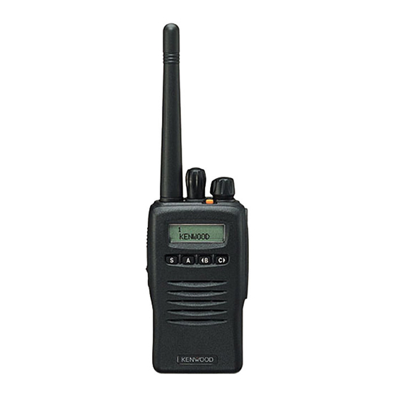
Kenwood TK-2140 Instruction Manual
Vhf/uhf fm transceiver
Hide thumbs
Also See for TK-2140:
- Service manual (45 pages) ,
- Instruction manual (31 pages) ,
- Mode d'emploi (31 pages)

Related Manuals for Kenwood TK-2140


Summary of Contents for Kenwood TK-2140
- Page 1 INSTRUCTION MANUAL VHF FM TRANSCEIVER TK-2140 UHF FM TRANSCEIVER TK-3140 © B62-1476-30 (K) 09 08 07 06 05 04 03...
- Page 2 HANK We are grateful you chose KENWOOD for your land mobile radio applications. We believe this easy-to-use transceiver will provide dependable communications to keep personnel operating at peak efficiency. KENWOOD transceivers incorporate the latest in advanced technology. As a result, we feel strongly that you will be pleased with the quality and features of this product.
- Page 3 For information on Ni-Cd battery recycling in your area, call (toll free) 1-800-8-BATTERY (1-800-822-8837). KENWOOD’s involvement in this program is part of our commitment to preserve our environment and conserve our natural resources.
-
Page 4: Table Of Contents
CONTENTS UNPACKING AND CHECKING EQUIPMENT ....1 ......... 1 UPPLIED CCESSORIES PREPARATION ..........2 ........2 ATTERY RECAUTIONS NSTALLING EMOVING THE PTIONAL ECHARGEABLE ATTERY ....... 7 ACK OR LKALINE ATTERY ...... 8 NSTALLING EMOVING LKALINE ATTERIES ......9 NSTALLING THE PTIONAL NTENNA ........ - Page 5 CONVENTIONAL OPERATION (Trunking Format) ...20 ..........20 RANSMITTING ............20 ECEIVING SYSTEM SCAN (Trunking Format) ......21 ........21 CANNING RUNKED YSTEMS ......21 CANNING ONVENTIONAL YSTEMS ..........22 OCKOUT ..........22 EVERT GROUP SCAN (Trunking Format) ......23 CONVENTIONAL OPERATION (Conventional Format) ..24 ..........24 RANSMITTING ............24 ECEIVING SCAN (Conventional Format) ........25 ..........25 RIORITY...
-
Page 6: Unpacking And Checking Equipment
UNPACKING AND CHECKING EQUIPMENT Note: The following unpacking instructions are for use by your KENWOOD dealer, an authorized KENWOOD service facility, or the factory. Carefully unpack the transceiver. We recommend that you identify the items listed in the following table before discarding the packing material. -
Page 7: Preparation
PREPARATION ATTERY RECAUTIONS ◆ Do not recharge the battery pack if it is already fully charged. Doing so may cause the life of the battery pack to shorten or the battery pack may be damaged. ◆ After recharging the battery pack, disconnect it from the charger. If the charger power is reset (turned ON after being turned OFF), recharging will start again and the battery pack will become overcharged. - Page 8 • Do not incinerate or apply heat to the battery! If the insulator is melted, the gas release vent or safety function is damaged, or the electrolyte is ignited, the battery may generate heat or smoke, rupture, or burst into flame. •...
- Page 9 • Do not use the battery pack if it is damaged in any way! The battery may generate heat or smoke, rupture, or burst into flame. • Do not solder directly onto the battery! If the insulator is melted or the gas release vent or safety function is damaged, the battery may generate heat or smoke, rupture, or burst into flame.
- Page 10 • Do not charge the battery for longer than the specified time! If the battery pack has not finished charging even after the regulated time has passed, stop it. The battery may generate heat or smoke, rupture, or burst into flame. •...
- Page 11 ■ Characteristics of the Li-ion Battery Pack • As the battery pack is charged and discharged repeatedly, the battery capacity decreases. • Even if the battery pack is unused, the battery pack degrades. • It takes a longer time to charge the battery pack in cooler areas.
-
Page 12: Installing / Removing The (Optional ) Rechargeable Battery Pack Or Alkaline Battery Case
NSTALLING EMOVING THE PTIONAL ECHARGEABLE ATTERY ACK OR LKALINE ATTERY 1 Match the guides of the battery pack with the corresponding grooves on the upper rear of the transceiver, then firmly press the battery pack to lock it in place. 2 Flip the safety catch into place to prevent accidentally pressing the release latch... -
Page 13: Installing / Removing Alkaline Batteries
NSTALLING EMOVING LKALINE ATTERIES ◆ Do not install batteries in a hazardous environment where sparks could cause an explosion. ◆ Never discard old batteries in fire; extremely high temperatures can cause batteries to explode. ◆ Do not short circuit the battery case terminals. ◆... -
Page 14: Installing The (Optional ) Antenna
NSTALLING THE PTIONAL NTENNA Screw the antenna into the connector on the top of the transceiver by holding the antenna at its base and turning it clockwise until secure. NSTALLING THE Note: When first installing the belt clip, you must remove the battery pack from the rear of the transceiver. -
Page 15: Nstalling The Over Over The Niversal Onnector
NSTALLING THE OVER OVER THE NIVERSAL ONNECTOR If you are not using the optional KMC-25 speaker/ microphone, install the cover over the univeral connector using the supplied 4 x 6 mm dressed screw. KMC-25) S NSTALLING THE PTIONAL PEAKER ICROPHONE 1 Insert the guide of the speaker/ microphone connector into the groove of the universal connector. -
Page 16: Getting Acquainted
GETTING ACQUAINTED Microphone Speaker q q q q q Antenna connector Connect an (optional) antenna here. w w w w w Rotary encoder Rotate this encoder to activate its programmable function. (System or Group Up/ Down in Trunking Format, and Group or Channel Up/ Down in Conventional Format.) For further details, contact your dealer. - Page 17 r r r r r LED indicator This LED lights red during transmission and green while receiving a signal. During Sel Call Alert, the LED flashes orange. If programmed by your dealer, when the battery pack power is low, the LED flashes red during transmission.
-
Page 18: Display
ISPLAY o i t y t i i h t e l i h t i i g i . s t s t i o l l (▼ i t c ( l l ( l l n i l y l r... -
Page 19: Programmable Auxiliary Functions
PROGRAMMABLE AUXILIARY FUNCTIONS Keys w, t, o and !0 {pages 11 and 12} can be programmed with the auxiliary functions listed in the following table. The keys can only be programmed with functions, depending on whether you are using Conventional Format or Trunking Format. Please contact your dealer for further details on these functions. - Page 20 i t c l a i These functions can be programmed only on key w, the encoder. This function can be programmed only on key t, the Auxiliary (orange) key, and on the programmable function key of the optional KMC-25 speaker/ microphone. This function can be programmed only on key !0 ’...
-
Page 21: Operation Overview
OPERATION OVERVIEW Your dealer can program your transceiver for either Trunking Format or Conventional Format. RUNKING ORMAT This format can handle up to 32 systems with up to 250 groups in each system. The transceiver can be used in both trunked mode and conventional mode. Systems, groups, and their functions are programmed by your dealer. -
Page 22: Operating Basics
OPERATING BASICS ON/ OFF WITCHING OWER Turn the Power switch/ Volume control clockwise to switch the transceiver ON. Turn the Power switch/ Volume control counterclock- wise to switch the transceiver OFF. DJUSTING THE OLUME Rotate the Power switch/ Volume control to adjust the volume. -
Page 23: Time - Out Timer (Tot)
(TOT) IMER The purpose of the Time-out Timer is to prevent any caller from using a channel for an extended period of time. If you continuously transmit for a period of time that exceeds the programmed time, the transceiver will stop transmitting and an alert tone will sound. -
Page 24: Trunked Operation (Trunking Format)
TRUNKED OPERATION (Trunking Format) LACING A ISPATCH 1 Select the desired system and group using the encoder and the System or Group keys. 2 Press the PTT switch, then speak into the microphone. Release the PTT switch to receive. • For best sound quality at the receiving station, hold the microphone approximately 1.5 inches (3 ~ 4 cm) from your mouth. -
Page 25: Conventional Operation (Trunking Format)
CONVENTIONAL OPERATION (Trunking Format) RANSMITTING 1 Select the desired system and group using the encoder and the System or Group keys. 2 Press the key programmed as Monitor to check whether or not the channel is free. • If the channel is busy, wait until it becomes free. 3 Press the PTT switch and speak into the microphone. -
Page 26: System Scan (Trunking Format)
SYSTEM SCAN (Trunking Format) If the Scan function is programmed, systems can be scanned by pressing the key programmed as Scan. When the Scan key is pressed, the SCN indicator and “-SCAN-” or the revert system/ group number, appear on the display and scanning starts. -
Page 27: Scan Lockout
OCKOUT If a programmable auxiliary key is programmed with Scan Del/Add, each system can be locked out of the scan sequence manually. The delete indicator ( s ) will appear on the display when the selected system is locked out. EVERT You can select revert systems and groups using the encoder and the System or Group keys. -
Page 28: Group Scan (Trunking Format)
GROUP SCAN (Trunking Format) Group Scan is available for both trunked and conventional systems. This feature is useful when more than one group is programmed in a system. Group Scan is set by your dealer on request. It scans the revert groups as well as groups that are allowed to be scanned. -
Page 29: Conventional Operation (Conventional Format)
CONVENTIONAL OPERATION (Conventional Format) RANSMITTING 1 Select the desired group and channel using the encoder and the Group or Channel keys. 2 Press the key programmed as Monitor to check whether or not the channel is free. • If the channel is busy, wait until it becomes free. 3 Press the PTT switch and speak into the microphone. -
Page 30: Scan (Conventional Format)
SCAN (Conventional Format) If the Scan function is programmed, groups or channels can be scanned by pressing the key programmed as Scan. Scan can be used as either Single Scan or Multi Scan. Single Scan monitors only the channels of a single group. -
Page 31: 2-Tone Signalling (Conventional Format)
2-TONE SIGNALLING (Conventional Format) 2-Tone Signalling is either activated or deactivated by your dealer. 2-Tone Signalling only opens the squelch when the transceiver receives two tones corresponding to those set up in the transceiver. When the squelch opens, you will be able to hear the caller without any further action. After a correct 2-Tone signal is received and the squelch opens, pressing the key programmed as Monitor will cancel the connection. -
Page 32: Fleetsync™: Alphanumeric 2-Way Paging Function
FleetSync™: ALPHANUMERIC 2-WAY PAGING FUNCTION FleetSync™ is an Alphanumeric 2-way Paging Function, and is a protocol owned by KENWOOD Corporation. FleetSync™ enables a variety of paging functions on your transceiver, some of which depend on dealer programming. UNCTIONS i t c... -
Page 33: Selcall (Selective Calling )
ELCALL ELECTIVE ALLING A Selcall is a voice call to a particular station or to a group of stations. ■ Transmitting 1 Select your desired system and group (or group and channel). 2 Press the A key to enter Selcall Mode. 3 Press the t t t t t B key or C s s s s s key to select the ID of the station you want to call. - Page 34 ■ View the Caller IDs in the Stack Memory If programmed by your dealer, the mail icon ( ) will flash when a Selcall call is received and stacked. 1 Press and hold the A key for more than 1 second to enter Stack Mode.
-
Page 35: Status Message
TATUS ESSAGE You can send and receive 2-digit Status messages (10 ~ 79) which may be decided in your talk group. Messages can contain up to 16 alphanumeric characters. A maximum of 9 received messages can be stored in the stack memory of your transceiver. These saved messages can be reviewed after reception. - Page 36 ■ Receiving The mail icon ( ) will flash and a calling ID or text message will appear when a Status call is received. • The display alternates between the caller ID and the message. Press any key to return to Normal Operation Mode. ■...
-
Page 37: Optional Short Messages Feature
■ Automatic Status Response If you pre-select a status number and then leave the transceier in Status Mode, the transceiver will automatically respond with that status number when a request from the base station is received. (The base station request function is optional.) PTIONAL HORT ESSAGES... -
Page 38: Audible User Feedback Tones
AUDIBLE USER FEEDBACK TONES The transceiver emits various tones to indicate the transceiver’s operating status. Contact your dealer for further information on these tones. l l a l l a l l o...