Table of Contents
Advertisement
Quick Links
Intel® Desktop Board
DQ67SW
Technical Product Specification
January 2011
Order Number: G14714-001US
®
The Intel
Desktop Board DQ67SW may contain design defects or errors known as errata that may cause the product to deviate from published
specifications. Current characterized errata are documented in the Intel Desktop Board DQ67SW Specification Update.
Advertisement
Table of Contents

Related Manuals for Intel BLKDQ67SW


Summary of Contents for Intel BLKDQ67SW
- Page 1 Order Number: G14714-001US ® The Intel Desktop Board DQ67SW may contain design defects or errors known as errata that may cause the product to deviate from published specifications. Current characterized errata are documented in the Intel Desktop Board DQ67SW Specification Update.
-
Page 2: Revision History
“undefined.” Intel reserves these for future definition and shall have no responsibility whatsoever for conflicts or incompatibilities arising from future changes to them. Intel desktop boards may contain design defects or errors known as errata, which may cause the product to deviate from published specifications. Current characterized errata are available on request. -
Page 3: Intended Audience
® Intended Audience The TPS is intended to provide detailed, technical information about the Intel Desktop Board DQ67SW and its components to the vendors, system integrators, and other engineers and technicians who need this level of information. It is specifically not intended for general audiences. - Page 4 Intel Desktop Board DQ67SW Technical Product Specification Other Common Notation Used after a signal name to identify an active-low signal (such as USBP0#) Gigabyte (1,073,741,824 bytes) GB/s Gigabytes per second Gb/s Gigabits per second Kilobyte (1024 bytes) Kbit Kilobit (1024 bits)
-
Page 5: Table Of Contents
1.1.3 Block Diagram ..............13 1.2 Legacy Considerations..............14 1.3 Online Support................14 1.4 Processor ..................14 ® 1.5 Intel Q67 Express Chipset ............... 15 1.6 System Memory ................15 1.6.1 Memory Configurations ............16 1.7 Graphics Subsystem ................ 18 1.7.1... - Page 6 Intel Desktop Board DQ67SW Technical Product Specification ® ® 2.4 Intel Management Engine BIOS Extension (Intel MEBX) Reset Header .................. 55 2.5 Mechanical Considerations ..............57 2.5.1 Form Factor................. 57 2.6 Electrical Considerations ..............58 2.6.1 Power Supply Considerations ..........58 2.6.2...
- Page 7 11. S/PDIF Header ................47 12. Internal Mono Speaker Header ............47 13. Front Panel Audio Header for Intel HD Audio........47 14. Front Panel Audio Header for AC ’97 Audio .......... 48 15. Front Panel USB Header ..............48 16.
- Page 8 Intel Desktop Board DQ67SW Technical Product Specification 28. Recommended Power Supply Current Values ........58 29. Fan Header Current Capability............59 30. Thermal Considerations for Components ..........61 31. Environmental Specifications............. 62 32. BIOS Setup Program Menu Bar............64 33. BIOS Setup Program Function Keys............ 64 34.
-
Page 9: Product Description
• Support for 1 Gb, 2 Gb, and 4 Gb memory technology • Support for up to 32 GB of system memory with four DIMMs using 4 Gb memory technology • Support for non-ECC memory • Integrated graphics support for processors with Intel ® Graphics Technology: Graphics ―... - Page 10 ― Four USB 2.0 ports are implemented with stacked back panel connectors (black) ― Eight USB 2.0 front panel ports are implemented through four dual-port internal headers • Six SATA interfaces through the Intel Q67 Express Chipset with Intel ® Rapid Storage Technology RAID support: ―...
-
Page 11: Board Layout
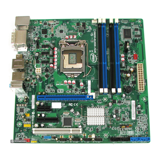
Product Description 1.1.2 Board Layout Figure 1 shows the location of the major components on Intel Desktop Board DQ67SW. Figure 1. Major Board Components Table 2 lists the components identified in Figure 1. -
Page 12: Components Shown In Figure 1
BIOS setup configuration jumper block ® ® Intel Management Engine BIOS Extension (Intel MEBX) Reset header SATA connectors Intel Fast Call for Help (Intel FCFH) header Front panel USB headers (4) IEEE 1394a front panel header S/PDIF header Rear chassis fan header... -
Page 13: Block Diagram
Product Description 1.1.3 Block Diagram Figure 2 is a block diagram of the major functional areas of the board. Figure 2. Block Diagram... -
Page 14: Legacy Considerations
Processor The board is designed to support the Intel Core i7, Intel Core i5, Intel Core i3, and Intel Pentium processors in an LGA1155 socket. Other processors may be supported in the future. This board is designed to support processors with a maximum TDP of 95 W. -
Page 15: Intel Q67 Express Chipset
Intel Q67 Express Chipset The Intel Q67 Express Chipset consisting of the Intel Q67 Platform Controller Hub (PCH) provides interfaces to the processor and the USB, SATA, LPC, audio, network, display, Conventional PCI, and PCI Express. The PCH is a centralized controller for the board’s I/O paths. -
Page 16: Memory Configurations
025414.htm 1.6.1 Memory Configurations The Intel Core i7, Intel Core i5, Intel Core i3, and Intel Pentium processors support the following types of memory organization: • Dual channel (Interleaved) mode. This mode offers the highest throughput for real world applications. Dual channel mode is enabled when the installed memory capacities of both DIMM channels are equal. -
Page 17: Memory Channel And Dimm Configuration
Product Description Figure 3 illustrates the memory channel and DIMM configuration. Figure 3. Memory Channel and DIMM Configuration... -
Page 18: Graphics Subsystem
Intel Desktop Board DQ67SW Technical Product Specification Graphics Subsystem The board supports system graphics through either Intel Graphics Technology or a PCI Express 2.0 x16 add-in graphics card. 1.7.1 Integrated Graphics ® The board supports integrated graphics through the Intel Flexible Display Interface ®... -
Page 19: Pci Express X16 Graphics
Product Description 1.7.2 PCI Express x16 Graphics The Intel Core i7, Intel Core i5, Intel Core i3, and Intel Pentium processors in an LGA1155 socket support discrete add in graphics cards through the PCI Express 2.0 x16 graphics connector: •... -
Page 20: Sata Interfaces
The location of the SATA connectors Figure 10, page 45 1.9.1.1 Serial ATA RAID The board supports the Intel Rapid Storage Technology (Intel RST) which provides the following RAID (Redundant Array of Independent Drives) levels: • RAID 0 - data striping •... -
Page 21: 1.10 Legacy I/O Controller
Rapid Recover Technology (Intel RRT). Intel Rapid Recover Technology is a feature of Intel Rapid Storage Technology. It uses RAID 1 (mirroring) functionality to copy data from a designated master drive to a designated recovery drive. The master drive data can be copied to the recovery drive either continuously or on request. -
Page 22: 1.11 Audio Subsystem
Intel Desktop Board DQ67SW Technical Product Specification 1.11 Audio Subsystem The board supports Intel High Definition Audio through the Realtek ALC888S audio codec as well as the DisplayPort interface. The Realtek ALC888S-based audio subsystem supports the following features: • 8-channel audio with independent multi-streaming stereo. -
Page 23: Back Panel Audio Connector Options
Product Description 1.11.2.1 Analog Audio Connectors The available configurable back panel audio connectors are shown in Figure 4. Item Description Audio line in Audio line out Mic in Figure 4. Back Panel Audio Connector Options The back panel audio connectors are configurable through the audio device drivers. For information about Refer to The back panel audio connectors... -
Page 24: 1.12 Lan Subsystem
• PCI Express power management support • Intel AMT 7.0 1.12.2 LAN Subsystem Software LAN software and drivers are available from Intel’s World Wide Web site. For information about Refer to Obtaining LAN software and drivers Section 1.3, page 14... -
Page 25: Rj-45 Lan Connector With Integrated Leds
Product Description 1.12.3 RJ-45 LAN Connector with Integrated LEDs Two LEDs are built into the RJ-45 LAN connector (shown in Figure 5). Item Description Link/Activity LED (green) Link Speed LED (green/yellow) Figure 5. LAN Connector LED Locations Table 4 describes the LED states when the board is powered up and the LAN subsystem is operating. -
Page 26: 1.13 Real-Time Clock Subsystem
Intel Desktop Board DQ67SW Technical Product Specification 1.13 Real-Time Clock Subsystem A coin-cell battery (CR2032) powers the real-time clock and CMOS memory. When the computer is not plugged into a wall socket, the battery has an estimated life of three years. When the computer is plugged in, the standby current from the power supply extends the life of the battery. -
Page 27: 1.14 Thermal Monitoring
Figure 6 shows the locations of the thermal sensors and fan headers. Item Description Thermal diode, located on processor die Processor fan header Front chassis fan header Thermal diode, located on the Intel Q67 PCH Rear chassis fan header Figure 6. Thermal Sensors and Fan Headers... -
Page 28: 1.15 Platform Management And Security
Intel Desktop Board DQ67SW Technical Product Specification 1.15 Platform Management and Security In addition to Intel AMT the Intel DQ67SW Desktop Board integrates several functions designed to manage the system and lower the total cost of ownership (TCO) of the system. -
Page 29: Intel Vpro™ Technology
Intel 82579LM Gigabit (10/100/1000 Mbits/s) Ethernet LAN controller • BIOS/SPI Flash (64 Mbits) NOTE Software with AMT capability is required to take advantage of Intel AMT platform management capabilities. 1.15.3.1.1 Intel AMT Features The key features of Intel AMT include: •... - Page 30 • System Defense 2. In addition to the in-bound and out-bound packet filtering of the previous generation, System Defense 2 is an Intel AMT feature that uses advanced heuristics to help protect against the propagation of worms through the use of preset packet filters. The number of new connections made to a specific port or IP address are counted over a specific time window.
- Page 31 Refer to http://www.intel.com/technology/platform- Intel Active Management Technology (Intel AMT) technology/intel-amt/index.htm 1.15.3.1.2 Intel AMT Software and Drivers Intel AMT software and drivers are available from Intel’s World Wide Web site. The package usually consists of the following components: ® ® • Intel...
- Page 32 Inside the firewall, this feature adapts Client Initiated Local Access (CILA); outside the firewall it uses Client Initiated Remote Access (CIRA). Many of the features of Intel AMT are available with Intel Fast Call for Help. These include Serial-over-LAN, IDE Redirection, KVM Remote Control and PC Alarm Clock.
-
Page 33: 1.16 Power Management
Product Description 1.15.3.6 Trusted Platform Module (TPM) The Nuvoton WPCT210 TPM version 1.2 revision 103 component is specifically designed to enhance platform security above-and-beyond the capabilities of today’s software by providing a protected space for key operations and other security critical tasks. -
Page 34: Acpi
Intel Desktop Board DQ67SW Technical Product Specification 1.16.1 ACPI ACPI gives the operating system direct control over the power management and Plug and Play functions of a computer. The use of ACPI with this board requires an operating system that provides full ACPI support. ACPI features include: •... -
Page 35: Power States And Targeted System Power
In order to support processor Deep Sx states, ME Power Package 1 (ME On in S0) must be selected in the BIOS setup. However, this will disable Intel AMT Out-of-Band (OOB) support, including the ability to wake the system using Intel AMT. -
Page 36: Wake-Up Devices And Events
Intel Desktop Board DQ67SW Technical Product Specification 1.16.1.2 Wake-up Devices and Events Table 7 lists the devices or specific events that can wake the computer from specific states. Table 7. Wake-up Devices and Events These devices/events can wake up the computer…... -
Page 37: Hardware Support
Product Description 1.16.2 Hardware Support CAUTION Ensure that the power supply provides adequate +5 V standby current if LAN wake capabilities and Instantly Available PC technology features are used. Failure to do so can damage the power supply. The total amount of standby current required depends on the wake devices supported and manufacturing options. -
Page 38: Fan Headers
Intel Desktop Board DQ67SW Technical Product Specification 1.16.2.2 Fan Headers The function/operation of the fan headers is as follows: • The fans are on when the board is in the S0 state • The fans are off when the board is in the S3, S4, or S5 state •... -
Page 39: Instantly Available Pc Technology
Product Description 1.16.2.4 Instantly Available PC Technology CAUTION For Instantly Available PC technology, the +5 V standby line for the power supply must be capable of providing adequate +5 V standby current. Failure to provide adequate standby current when implementing Instantly Available PC technology can damage the power supply. -
Page 40: Location Of The Standby Power Led (Green)
Intel Desktop Board DQ67SW Technical Product Specification 1.16.2.9 +5 V Standby Power LED The green +5 V standby power indicator LED shows that power is still present even when the computer appears to be off. Figure 7 shows the location of the Standby Power indicator LED on the board. -
Page 41: Technical Reference
Technical Reference Memory Resources 2.1.1 Addressable Memory The board utilizes 32 GB of addressable system memory. Typically the address space that is allocated for PCI Conventional bus add-in cards, PCI Express configuration space, BIOS (SPI Flash device), and chipset overhead resides above the top of DRAM (total system memory). -
Page 42: Detailed System Memory Address Map
Intel Desktop Board DQ67SW Technical Product Specification Figure 8. Detailed System Memory Address Map... -
Page 43: Memory Map
Technical Reference 2.1.2 Memory Map Table 8 lists the system memory map. Table 8. System Memory Map Address Range Address Range Size Description 1024 K - 33550336 K 100000 – 7FFC00000 32764 MB Extended memory 960 K - 1024 K F0000 - FFFFF 64 KB Runtime BIOS... -
Page 44: Back Panel Connectors
Intel Desktop Board DQ67SW Technical Product Specification 2.2.1 Back Panel Connectors Figure 9 shows the location of the back panel connectors for the board. Item Description USB 3.0 ports DVI-I connector DVI-D connector DisplayPort connector USB ports eSATA ports IEEE 1394a connector... -
Page 45: Component-Side Connectors And Headers
Technical Reference 2.2.2 Component-side Connectors and Headers Figure 10 shows the locations of the component-side connectors and headers. Figure 10. Component-side Connectors and Headers Table 9 lists the component-side connectors and headers identified in Figure 10. -
Page 46: Front Panel Usb Header
Intel Desktop Board DQ67SW Technical Product Specification Table 9. Component-side Connectors and Headers Shown in Figure 10 Item/callout from Figure 10 Description PCI Conventional bus add-in card connector Front panel audio header PCI Express x4 bus add-in card connector Internal mono speaker header... -
Page 47: Serial Port Header
S/PDIF out Key (no pin) +5V_DC Table 12. Internal Mono Speaker Header Signal Name − Table 13. Front Panel Audio Header for Intel HD Audio Signal Name Signal Name [Port 1] Left channel Ground [Port 1] Right channel PRESENCE# (Dongle present) -
Page 48: Front Panel Audio Header For Ac '97 Audio
Intel Desktop Board DQ67SW Technical Product Specification Table 14. Front Panel Audio Header for AC ’97 Audio Signal Name Signal Name AUD_GND MIC_BIAS AUD_GND FP_OUT_R FP_RETURN_R AUD_5V KEY (no pin) FP_OUT_L FP_RETURN_L NOTE Not all AC ’97 signals are supported; specifically, pins 4, 6, 7, and 10 are not supported. -
Page 49: Processor (4-Pin) Fan Header
Technical Reference Table 18. Processor (4-Pin) Fan Header Signal Name Ground +12 V FAN_TACH FAN_CONTROL Table 19. Front and Rear Chassis Fan Headers 4-Wire Support 3-Wire Support Ground Ground +12 V FAN_POWER FAN_TACH FAN_TACH FAN_CONTROL Table 20. Front Panel IEEE 1394a Header Signal Name Signal Name Data A (positive) -
Page 50: Processor Core Power Connector
Main power – a 2 x 12 connector. This connector is compatible with 2 x 10 connectors previously used on Intel Desktop boards. The board supports the use of ATX12V power supplies with either 2 x 10 or 2 x 12 main power cables. When using a power supply with a 2 x 10 main power cable, pins 11, 12, 23, and 24 must remain unconnected. -
Page 51: Connection Diagram For Front Panel Header
Technical Reference 2.2.2.4 Front Panel Header This section describes the functions of the front panel header. Table 23 lists the signal names of the front panel header. Figure 11 is a connection diagram for the front panel header. Table 23. Front Panel Header Signal Description Signal... -
Page 52: Alternate Front Panel Power Led Header
Intel Desktop Board DQ67SW Technical Product Specification 2.2.2.4.2 Reset Switch Header Pins 5 and 7 can be connected to a momentary single pole, single throw (SPST) type switch that is normally open. When the switch is closed, the board resets and runs the POST. -
Page 53: Connection Diagram For Front Panel Usb Headers
Technical Reference 2.2.2.6 Front Panel USB Headers Figure 12 is a connection diagram for the front panel USB headers. NOTE • The +5 V DC power on the USB headers is fused. • Use only a front panel USB connector that conforms to the USB 2.0 specification for high-speed USB devices. -
Page 54: Bios Configuration Jumper Block
Intel Desktop Board DQ67SW Technical Product Specification BIOS Configuration Jumper Block CAUTION Do not move the jumper with the power on. Always turn off the power and unplug the power cord from the computer before changing a jumper setting. Otherwise, the board could be damaged. -
Page 55: Reset Header
MEBX) Reset Header ® The Intel MEBX reset header (see Figure 14) allows you to reset the Intel AMT configuration to the factory defaults. Momentarily shorting pins 1 and 2 with a jumper (not supplied) will accomplish the following: •... -
Page 56: Intel Mebx Reset Header
Intel Desktop Board DQ67SW Technical Product Specification Figure 14. Intel MEBX Reset Header Table 27. Intel MEBX Reset Header Signals Function PCH.AK24 (PCH_RTCRST_PULLUP) Ground No connection... -
Page 57: Mechanical Considerations
Technical Reference Mechanical Considerations 2.5.1 Form Factor The board is designed to fit into a microATX form-factor chassis. Figure 15 illustrates the mechanical form factor for the board. Dimensions are given in inches [millimeters]. The outer dimensions are 9.60 inches by 9.60 inches [243.84 millimeters by 243.84 millimeters]. -
Page 58: Electrical Considerations
Intel Desktop Board DQ67SW Technical Product Specification Electrical Considerations 2.6.1 Power Supply Considerations CAUTION The +5 V standby line from the power supply must be capable of providing adequate +5 V standby current. Failure to do so can damage the power supply. The total amount of standby current required depends on the wake devices supported and manufacturing options. -
Page 59: Fan Header Current Capability
Technical Reference 2.6.2 Fan Header Current Capability CAUTION The processor fan must be connected to the processor fan header, not to a chassis fan header. Connecting the processor fan to a chassis fan header may result in onboard component damage that will halt fan operation. Table 29 lists the current capability of the fan headers. -
Page 60: Thermal Considerations
Use of a processor heat sink that provides omni-directional airflow to maintain required airflow across the processor voltage regulator area is highly recommended. For a list of chassis that have been tested with Intel desktop boards please refer to the following website: http://www3.intel.com/cd/channel/reseller/asmo-na/eng/tech_reference/53211.htm... -
Page 61: Thermal Considerations For Components
Item Description Processor voltage regulator area Processor Intel Q67 Express Chipset Figure 16. Localized High Temperature Zones Table 30 provides maximum case temperatures for the components that are sensitive to thermal changes. The operating temperature, current load, or operating frequency could affect case temperatures. -
Page 62: Reliability
Intel Desktop Board DQ67SW Technical Product Specification Reliability The Mean Time Between Failures (MTBF) prediction is calculated using component and subassembly random failure rates. The calculation is based on the Telcordia "Reliability Prediction Procedure for Electronic Equipment" (Reference Model Telcordia SR-332 Issue 2, Reference Method Telcordia (Bellcore) Method I, Case 3). -
Page 63: Overview Of Bios Features
Overview of BIOS Features Introduction The board uses an Intel BIOS that is stored in a 64 Mbit (8,192 KB) Serial Peripheral Interface Flash Memory (SPI Flash) device which can be updated using a set of utilities. The SPI Flash contains the BIOS Setup program, POST, LAN EEPROM information, Plug and Play support, and other firmware. -
Page 64: Bios Setup Program Menu Bar
Intel Desktop Board DQ67SW Technical Product Specification Table 32 lists the BIOS Setup program menu features. Table 32. BIOS Setup Program Menu Bar Configura- Maintenance Main tion Performance Security Power Boot Intel ME Exit Clears Displays Configures Configures Sets Configures... -
Page 65: System Management Bios (Smbios)
Overview of BIOS Features System Management BIOS (SMBIOS) SMBIOS is a Desktop Management Interface (DMI) compliant method for managing computers in a managed network. The main component of SMBIOS is the Management Information Format (MIF) database, which contains information about the computing system and its components. -
Page 66: Bios Updates
Intel Desktop Board DQ67SW Technical Product Specification BIOS Updates The BIOS can be updated using either of the following utilities, which are available on the Intel World Wide Web site: ® • Intel Express BIOS Update utility, which enables automated updating while in the Windows environment. -
Page 67: Custom Splash Screen
During POST, an Intel splash screen is displayed by default. This splash screen can be augmented with a custom splash screen. The Intel Integrator’s Toolkit that is available from Intel can be used to create a custom splash screen. Refer to For information about ®... -
Page 68: Boot Options
Intel Desktop Board DQ67SW Technical Product Specification Boot Options In the BIOS Setup program, the user can choose to boot from a hard drive, optical drive, removable drive, or the network. The default setting is for the optical drive to be the first boot device, the hard drive second, removable drive third, and the network fourth. -
Page 69: Hard Disk Drive Password Security Feature
Overview of BIOS Features Hard Disk Drive Password Security Feature The Hard Disk Drive Password Security feature blocks read and write accesses to the hard disk drive until the correct password is given. Hard Disk Drive Passwords are set in BIOS SETUP and are prompted for during BIOS POST. For convenient support of S3 resume, the system BIOS will automatically unlock drives on resume from S3. -
Page 70: Bios Security Features
Intel Desktop Board DQ67SW Technical Product Specification NOTE Hard Disk Drive Password Security is not supported in PCH RAID mode. Secured hard disk drives attached to the system when the system is in PCH RAID mode will not be accessible due to the disabling of BIOS Hard Disk Drive Password support. -
Page 71: Supervisor And User Password Functions
Overview of BIOS Features Table 37 shows the effects of setting the supervisor password and user password. This table is for reference only and is not displayed on the screen. Table 37. Supervisor and User Password Functions Password Password Password Supervisor to Enter During... - Page 72 Intel Desktop Board DQ67SW Technical Product Specification...
-
Page 73: Error Messages And Beep Codes
Error Messages and Beep Codes Speaker The board-mounted piezoelectric speaker provides audible error code (beep code) information during POST. For information about Refer to The location of the onboard speaker Figure 1, page 11 BIOS Beep Codes Whenever a recoverable error occurs during POST, the BIOS causes the board’s piezoelectric speaker to beep an error message describing the problem (see Table 38). -
Page 74: Front-Panel Power Led Blink Codes
Intel Desktop Board DQ67SW Technical Product Specification Front-panel Power LED Blink Codes Whenever a recoverable error occurs during POST, the BIOS causes the board’s front panel power LED to blink an error message describing the problem (see Table 39). Table 39. Front-panel Power LED Blink Codes... -
Page 75: Port 80H Post Codes
Error Messages and Beep Codes Port 80h POST Codes During the POST, the BIOS generates diagnostic progress codes (POST codes) to I/O port 80h. If the POST fails, execution stops and the last POST code generated is left at port 80h. This code is useful for determining the point where an error occurred. Displaying the POST codes requires a PCI bus add-in card, often called a POST card. - Page 76 Intel Desktop Board DQ67SW Technical Product Specification Table 42. Port 80h POST Codes Port 80 Code Progress Code Enumeration ACPI S States 0x00,0x01,0x02,0x03,0x04,0x05 Entering S0, S2, S3, S4, or S5 state 0x10,0x20,0x30,0x40,0x50 Resuming from S2, S3, S4, S5 Security Phase (SEC)
- Page 77 Error Messages and Beep Codes Table 42. Port 80h POST Codes (continued) Port 80 Code Progress Code Enumeration PEIMs/Recovery 0x31 Crisis Recovery has initiated 0x33 Loading recovery capsule 0x34 Start recovery capsule/ valid capsule is found CPU Initialization CPU PEI Phase 0x41 Begin CPU PEI Init 0x42...
- Page 78 Intel Desktop Board DQ67SW Technical Product Specification Table 42. Port 80h POST Codes (continued) Port 80 Code Progress Code Enumeration 0x60 BDS driver entry point initialize 0x61 BDS service routine entry point (can be called multiple times) 0x62 BDS Step2...
- Page 79 Error Messages and Beep Codes Table 42. Port 80h POST Codes (continued) Port 80 Code Progress Code Enumeration Removable Media 0xB8 Resetting removable media 0xB9 Disabling removable media 0xBA Detecting presence of a removable media (IDE, CDROM detection etc.) 0xBB Enabling/configuring a removable media DXE Core 0xE4...
-
Page 80: Typical Port 80H Post Sequence
Intel Desktop Board DQ67SW Technical Product Specification Table 43. Typical Port 80h POST Sequence POST Code Description Initializing a chipset component Reading SPD from memory DIMMs Detecting presence of memory DIMMs Configuring memory Testing memory Loading recovery capsule Entered DXE phase... -
Page 81: Regulatory Compliance And Battery Disposal Information
Electromagnetic Compatibility (EMC) standards • Product certification markings 5.1.1 Safety Standards The Intel Desktop Board DQ67SW complies with the safety standards stated in Table 44 when correctly installed in a compatible host system. Table 44. Safety Standards Standard Title CSA/UL 60950-1 Information Technology Equipment –... -
Page 82: European Union Declaration Of Conformity Statement
European Union Declaration of Conformity Statement ® We, Intel Corporation, declare under our sole responsibility that the product Intel Desktop Board DQ67SW is in conformity with all applicable essential requirements necessary for CE marking, following the provisions of the European Council Directive 2004/108/EC (EMC Directive), 2006/95/EC (Low Voltage Directive), and 2002/95/EC (ROHS Directive). -
Page 83: Product Ecology Statements
恰当的重复使用处理。 请参考http://www.intel.com/intel/other/ehs/product_ecology 了解此计划的详情,包括涉及产品之范围、回收地点、运送指导、条款和条件等。 Deutsch Als Teil von Intels Engagement für den Umweltschutz hat das Unternehmen das Intel Produkt-Recyclingprogramm implementiert, das Einzelhandelskunden von Intel Markenprodukten ermöglicht, gebrauchte Produkte an ausgewählte Standorte für ordnungsgemäßes Recycling zurückzugeben. Details zu diesem Programm, einschließlich der darin eingeschlossenen Produkte, verfügbaren Standorte, Versandanweisungen, Bedingungen usw., finden Sie auf der... - Page 84 Français Dans le cadre de son engagement pour la protection de l'environnement, Intel a mis en œuvre le programme Intel Product Recycling Program (Programme de recyclage des produits Intel) pour permettre aux consommateurs de produits Intel de recycler les produits usés en les retournant à...
-
Page 85: Emc Regulations
şartlar v.s dahil bütün ayrıntılarını ögrenmek için lütfen http://www.intel.com/intel/other/ehs/product_ecology Web sayfasına gidin. 5.1.4 EMC Regulations The Intel Desktop Board DQ67SW complies with the EMC regulations stated in Table 45 when correctly installed in a compatible host system. Table 45. EMC Regulations Regulation Title... - Page 86 • Consult the dealer or an experienced radio/TV technician for help. Any changes or modifications to the equipment not expressly approved by Intel Corporation could void the user’s authority to operate the equipment. Tested to comply with FCC standards for home or office use.
- Page 87 Regulatory Compliance and Battery Disposal Information Japan VCCI Statement Japan VCCI Statement translation: This is a Class B product based on the standard of the Voluntary Control Council for Interference from Information Technology Equipment (VCCI). If this is used near a radio or television receiver in a domestic environment, it may cause radio interference.
-
Page 88: Energy Star* 5.0, E-Standby, And Erp Compliance
Compliance The US Department of Energy and the US Environmental Protection Agency have continually revised the ENERGY STAR requirements. Intel has worked directly with these two governmental agencies in the definition of new requirements. Intel Desktop Board DQ67SW meets the following program requirements in an... -
Page 89: Regulatory Compliance Marks (Board Level)
Regulatory Compliance and Battery Disposal Information 5.1.6 Regulatory Compliance Marks (Board Level) Intel Desktop Board DQ67SW has the regulatory compliance marks shown in Table 46. Table 46. Regulatory Compliance Marks Description Mark UL joint US/Canada Recognized Component mark. Includes adjacent UL file number for Intel Desktop Boards: E210882. -
Page 90: Battery Disposal Information
Intel Desktop Board DQ67SW Technical Product Specification Battery Disposal Information CAUTION Risk of explosion if the battery is replaced with an incorrect type. Batteries should be recycled where possible. Disposal of used batteries must be in accordance with local environmental regulations. - Page 91 Regulatory Compliance and Battery Disposal Information PRECAUCIÓN Existe peligro de explosión si la pila no se cambia de forma adecuada. Utilice solamente pilas iguales o del mismo tipo que las recomendadas por el fabricante del equipo. Para deshacerse de las pilas usadas, siga igualmente las instrucciones del fabricante.
- Page 92 Intel Desktop Board DQ67SW Technical Product Specification AWAS Risiko letupan wujud jika bateri digantikan dengan jenis yang tidak betul. Bateri sepatutnya dikitar semula jika boleh. Pelupusan bateri terpakai mestilah mematuhi peraturan alam sekitar tempatan. OSTRZEŻENIE Istnieje niebezpieczeństwo wybuchu w przypadku zastosowania niewłaściwego typu baterii.
- Page 93 Regulatory Compliance and Battery Disposal Information...
- Page 94 Intel Desktop Board DQ67SW Technical Product Specification...