Chamberlain Elite RSW12V Installation Manual
Vehicular swing gate operator
Hide thumbs
Also See for Elite RSW12V:
- Quick start (2 pages) ,
- User manual (8 pages) ,
- Wiring diagram (2 pages)
Table of Contents
Advertisement
RSW12V
V E H I C U L A R S W I N G G A T E O P E R A T O R
I N S T A L L A T I O N M A N U A L
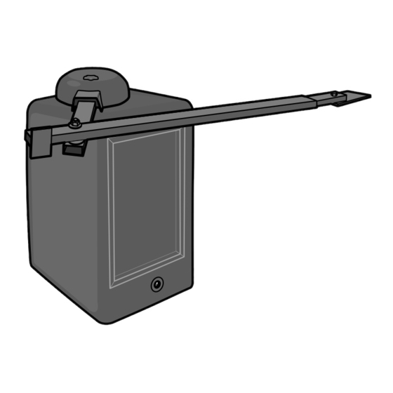
Your model may look different than the model illustrated in this manual.
STOP
THIS PRODUCT IS TO BE
INSTALLED AND SERVICED BY
A TRAINED GATE SYSTEMS
TECHNICIAN ONLY.
Visit www.liftmaster.com to
locate a professional installing
dealer in your area.
UL325
compliant
& RSW12VH
™
IMPORTANT NOTE: The gate operation may be
limited until the battery is fully charged.
This model is for use on vehicular
passage gates ONLY and not intended
for use on pedestrian passage gates.
This model is intended for use in
Class I and Class II vehicular swing
gate applications.
UL991
compliant
™
Advertisement
Table of Contents
Troubleshooting

Related Manuals for Chamberlain Elite RSW12V


Summary of Contents for Chamberlain Elite RSW12V
- Page 1 A TRAINED GATE SYSTEMS This model is intended for use in TECHNICIAN ONLY. Class I and Class II vehicular swing Visit www.liftmaster.com to gate applications. locate a professional installing dealer in your area. UL325...
-
Page 2: Table Of Contents
TABLE OF CONTENTS PROGRAMMING SAFETY Remote Controls Safety Symbol and Signal Word Review Keyless Entry UL325 Model Classifications Erase All Codes Safety Installation Information Alternate Radio Receiver Installation Gate Construction Information Required Safety Protection Devices Important Safety Information ADDITIONAL FEATURES 25-26 Timer-To-Close INTRODUCTION... -
Page 3: Ul325 Model Classifications
SAFETY » UL325 MODEL CLASSIFICATIONS CLASS I – RESIDENTIAL VEHICULAR GATE OPERATOR A vehicular gate operator (or system) intended for use in a home of one-to four single family dwellings, or a garage or parking area associated therewith. CLASS II – COMMERCIAL/GENERAL ACCESS VEHICULAR GATE OPERATOR A vehicular gate operator (or system) intended for use in a commercial location or building such as a multi-family housing unit (five or more single family units) hotel,... -
Page 4: Safety Installation Information
SAFETY » SAFETY INSTALLATION INFORMATION 1. Vehicular gate systems provide convenience and security. Gate systems are 8. Controls intended for user activation must be located at least 6 feet (1.8 m) comprised of many component parts. The gate operator is only one away from any moving part of the gate and where the user is prevented from component. -
Page 5: Gate Construction Information
SAFETY » GATE CONSTRUCTION INFORMATION Vehicular gates should be installed in accordance with ASTM F2200: Standard Specification for Automated Vehicular Gate Construction. For a copy, contact ASTM directly at 610-832-9585 or www.astm.org. GENERAL REQUIREMENTS Gates shall be constructed in accordance with the provisions given for the 3.1.4 Positive stops shall be required to limit travel to the designed fully open and appropriate gate type listed, refer to ASTM F2200 for additional gate types. -
Page 6: Required Safety Protection Devices
SAFETY » REQUIRED SAFETY PROTECTION DEVICES To prevent SERIOUS INJURY or DEATH from a moving gate: • Entrapment protection devices MUST be installed to protect anyone who may • Locate entrapment protection devices to protect between moving gate and RIGID come near a moving gate. -
Page 7: Important Safety Information
SAFETY » IMPORTANT SAFETY INFORMATION INSTALLATION To prevent SERIOUS INJURY or DEATH from a moving gate: • Pinch points must be guarded at all times. Install enclosed-style gate tracks and • Entrapment protection devices MUST be installed to protect anyone who may roller guards. - Page 8 • To reduce the risk of FIRE or INJURY to persons use ONLY LiftMaster part • ALWAYS keep people and objects away from the gate. NO ONE SHOULD CROSS 29-NP712 for replacement batteries.
-
Page 9: Introduction
INTRODUCTION » OPERATOR SPECIFICATIONS + CARTON INVENTORY + HARDWARE INVENTORY OPERATOR SPECIFICATIONS This model is intended for use in vehicular swing gate applications: Gate Classifications: CLASS I & II Main Supply (Motor): 12 Vdc Accessory Power: 12 V nominal Class II battery voltage source is limited to: •... -
Page 10: Installation
INSTALLATION » SITE PREPARATION + TYPES OF INSTALLATIONS SITE PREPARATION BEFORE installing the operator, be sure to check the following: • Gate is constructed and installed according to ASTM F2200 standards • Gate fits specifications of operator • National and local building codes •... -
Page 11: Standard Installation
INSTALLATION » STANDARD INSTALLATION CONCRETE PAD AND OPERATOR ATTACHMENT MOUNTING FOOTPRINT 14" 13.6" 12.2" 4 Concrete Anchors 17" 1/2" x 3 1/2" NOTE: An alternative to a concrete pad is to post mount the 6" Above Ground operator (refer to accessories). - Page 12 INSTALLATION » STANDARD INSTALLATION POSITION THE GATE BRACKET SAMPLE STANDARD INSTALLATION IS SHOWN ON PREVIOUS PAGE. Gate Hinge Center D MINUS 10" Long Arm 10" Short Arm DISTANCE Concrete Pad Dimension ( ) thru ( ) are from the center of one pivot point to the center of another pivot point. Caution: If the gate is longer than 18 feet, follow CHART A: A-2 If this dimension is...
-
Page 13: Compact Installation Only
INSTALLATION » COMPACT INSTALLATION ONLY DETERMINE LOCATION FOR CONCRETE PAD TOP VIEW OF OPERATOR AND GATE AND OPERATOR DO NOT run the operator until instructed. Gate Hinge Center Refer to the illustration to determine the measurements and location of the concrete pad. - Page 14 INSTALLATION » COMPACT INSTALLATION ONLY SHORTEN THE OPERATOR ARM For a compact installation the operator arm will have to be shortened. Take the operator arm apart and remove the inner sleeves from the outer tubing. Cut the outer tubing of the operator arm to the lengths shown. Put the arm back together and adjust the arm to the measurements LONG ARM SECTION as shown.
-
Page 15: Standard And Compact Installation
INSTALLATION » STANDARD INSTALLATION + COMPACT INSTALLATION WELD THE OPERATOR ARM Once the operator arm measurements are verified: Weld the gate bracket to the gate. Weld the short arm section. Weld the long arm section. NOTE: Completely weld around the outer tubing and bracket. SECURE THE OPERATOR ARM TO THE OUTPUT SHAFT Position the operator arm onto the output shaft so that the pin slides into... -
Page 16: Power Wiring
WIRING » POWER WIRING POWER WIRING This operator can be powered by the internal receptacle, an external receptacle or a solar panel (not provided). INTERNAL RECEPTACLE 120 VAC POWER WIRE (STRANDED COPPER WIRE) Wire Gauge 16 - 100 feet (30 m) Wire Gauge 10 - 1000 feet (305 m) CHGR CTRL... -
Page 17: Connect Batteries
For solar applications, a minimum of 20W solar panels and two 7AH batteries are recommended. For Zone 3 cold weather sites, one 33AH battery is recommended. We recommend LiftMaster low power draw accessories to minimize power draw, refer to accessory page. -
Page 18: Primary/Secondary Operators
WIRING » PRIMARY / SECONDARY OPERATORS PRIMARY/SECONDARY OPERATORS NOTE: Use the Dual Gate Wiring Kit. Refer to the accessory page for more information. Before digging, contact local underground utility locating companies. Choose one operator to be the primary and the other operator to be the secondary. PRIMARY OPERATOR NOTES: •... -
Page 19: Adjustment
ADJUSTMENT » LEARN LIMITS To reduce the risk of SEVERE INJURY or DEATH: • Without a properly installed safety reversal system, persons (particularly small • NEVER use force adjustments to compensate for a binding or sticking gate. children) could be SERIOUSLY INJURED or KILLED by a moving gate. •... - Page 20 ADJUSTMENT » LEARN LIMITS SINGLE GATE LEFT-HAND SIDE Close the gate. Make sure the operator arm is properly seated on the output shaft (the pin must fit into the slot). Make sure the handle is released on the operator arm and the learn limit cam is touching the learn limit switch. PROGRAM OPEN Manually open the gate to the desired open position.
- Page 21 ADJUSTMENT » LEARN LIMITS SINGLE GATE RIGHT-HAND SIDE Close the gate. Make sure the operator arm is properly seated on the output shaft (the pin must fit into the slot). Make sure the handle is released on the operator arm and the learn limit cam is touching the learn limit switch. PROGRAM OPEN Manually open the gate to the desired open position.
- Page 22 ADJUSTMENT » LEARN LIMITS DUAL GATE (LEFT-SIDE PRIMARY OPERATOR) Close the gates. Make sure the operator arm is properly seated on the output shaft (the pin must fit into the slot) of both operators and the learn limit cam is touching the learn limit switch on both operators.
- Page 23 ADJUSTMENT » LEARN LIMITS DUAL GATE (RIGHT-SIDE PRIMARY OPERATOR) Close the gates. Make sure the operator arm is properly seated on the output shaft (the pin must fit into the slot) of both operators and the learn limit cam is touching the learn limit switch on both operators.
-
Page 24: Force Adjustment
ADJUSTMENT FORCE ADJUSTMENT + TEST » FORCE ADJUSTMENT The operator is equipped with an obstruction sensing feature. If the gate encounters an obstruction the operator will automatically reverse direction for a short time and stop. Based on the length and weight of the gate it may be necessary to make force SINGLE BUTTON adjustments. -
Page 25: Programming
PROGRAMMING » REMOTE CONTROLS + KEYLESS ENTRY + ERASE ALL CODES + ALTERNATE RADIO RECEIVER INSTALLATION A combined total of 50 remote controls and keyless entry PINs can be programmed to the operator. For highest level of security, we recommend the Security✚ ®... -
Page 26: Additional Features
If the Timer-to-Close feature is enabled and you would like the gate to remain open, open the gate fully, then press the reset button. The next command given by a LiftMaster remote control or SINGLE BUTTON on the control board will close the gate and return the operator to normal operation. -
Page 27: Entrapment Protection Devices
ADDITIONAL FEATURES » ENTRAPMENT PROTECTION DEVICES To prevent SERIOUS INJURY or DEATH from a moving gate: • Entrapment protection devices MUST be installed to protect anyone who may • Locate entrapment protection devices to protect between moving gate and RIGID come near a moving gate. -
Page 28: Operation And Maintenance
OPERATION AND MAINTENANCE » MANUAL DISCONNECT + RESET BUTTON + REMOTE CONTROL + SLEEP MODE MANUAL DISCONNECT Release the handle on the operator arm to allow the gate to be opened and closed manually. On a dual gate application the handle must be released on both operators. To resume normal function tighten the handle by pushing it down. -
Page 29: Maintenance
BATTERY The battery should be replaced every three years. Use only LiftMaster part 29-NP712 for replacement batteries. The operator comes with one 7AH battery. A second 7AH (29-NP712) battery may be added or one 33AH (A12330SGLPK) may be used in place of the 7AH batteries. -
Page 30: Troubleshooting
TROUBLESHOOTING » DIAGNOSTIC ERROR CODES CHART The operator is programmed with self-diagnostic capabilities. The diagnostic LED will flash a number of times then pause signifying it has found a potential issue. Consult Diagnostic Error Codes Chart below. Operator is in sleep mode - Normal Operation CONTINUOUS FLASHES (HEARTBEAT) POWER ON Stop is not connected. -
Page 31: Troubleshooting Chart
TROUBLESHOOTING » TROUBLESHOOTING CHART • Power not connected. Make sure the AC/Solar input is connected and that at least one battery is connected OPERATOR DOES with the corresponding fuse intact. NOT RUN. DIAGNOSTIC LED • Low or defective battery. Check the battery to make sure that the red wire goes to the positive terminal of the battery and the NOT ON. -
Page 32: Troubleshooting Chart
TROUBLESHOOTING » TROUBLESHOOTING CHART • Battery not connected. At least one charged battery must be connected for the operator remote control to operate. Verify battery OPERATOR DOES NOT fuse is intact. Check battery connections and battery voltage to be above 11.5Vdc. Replace batteries if necessary. RESPOND TO COMMAND. -
Page 34: Accessories
™ Single-button to 4-button, visor or key chain. Additionally, Passport remote controls are ideal for integration with Telephone ™ Entry and Access Control Systems. Contact your authorized LiftMaster dealer for details. 3-BUTTON SECURITY✚ REMOTE CONTROL ® The 3-button remote control can be programmed to control the operator. Includes visor clip. -
Page 35: Accessories
ACCESSORIES WIRELESS ACCESS CONTROL RECEIVER Access control receiver for up to 450 Security✚ remote controls. ® Model STAR450-315 HEATER Keeps operator, gearbox and batteries at suitable temperature when outside temperature is below 0°F for extended periods of time. Models HTRKITRSW (for Swing operator, includes bracket for optimal heater location) and G6518CSW (Swing replacement heater only) LOOP DETECTOR Low power loop detectors. -
Page 36: Warranty
WARRANTY LIFTMASTER THREE YEAR LIMITED WARRANTY The Chamberlain Group, Inc. warrants to the first purchaser of this product, for the structure in which this product is originally installed, that it is free from defect in materials and/or workmanship for a period of THREE years from the date of purchase. The proper operation of this product is dependent on your compliance with the instructions regarding installation, operation, maintenance and testing.