Table of Contents
Advertisement
Quick Links
Download this manual
See also:
User Manual
Advertisement
Table of Contents

Related Manuals for Fujitsu XG700 - Switch


Summary of Contents for Fujitsu XG700 - Switch
- Page 1 P3N1-E041-01EN XG700 Hardware Guide...
-
Page 2: Preface
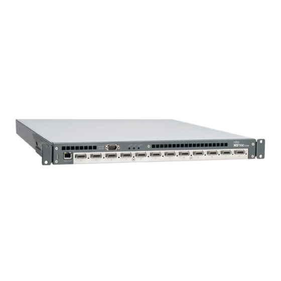
Preface You have purchased the XG700, a compact, 12 port 10 Gigabit Ethernet layer 2 switch that achieves unsurpassed standards of high throughput and low-latency performance. This manual explains the procedures required to install your XG700 and should be read and understood before you start using your XG700. -
Page 3: For Safe Use Of The Xg700
For Safe Use of the XG700 This manual contains important information to ensure the safe use of your XG700. Be sure to thoroughly read and understand its contents before attempting to use the XG700. After reading, store this manual in a safe place for future reference. PFU has made every effort to ensure the safety of the user and others, and to prevent property damage. - Page 4 This symbol indicates the possibility of serious or fatal injury if the XG700 is WARNING not used properly. For your safety and that of others, please follow these guidelines. Category Warning Danger of Never attempt to disassemble, dismantle, upgrade, or recycle the XG700 by yourself. electric shock Do not place objects on the XG700, as there is a risk of electric shock, fire, and/or damage.
- Page 5 This symbol indicates the possibility of minor or moderate personal injury, as CAUTION well as damage to the XG700 and/or to other users and their property, if the XG700 is not used properly. Category Caution Danger of device Do not place the XG700 on its side or stack up multiple XG700s. Doing so may damage the XG700. damage Do not install the XG700 in an unstable place (such as on a slanted surface or a place subjected to vibrations).
-
Page 6: No Self Maintenance
• Use of this hardware guide, the XG700, its firmware, and the management software are the responsibility of the user. • Fujitsu and its partners accept no responsibility for any errors or data loss arising from use of the XG700. Before using the XG700, it should be understood that the XG700 is not guaranteed against failure for any more than the original purchase price. -
Page 7: Electromagnetic Compatibility
Do not use the XG700 for High Safety Required Use without otherwise ensuring the safety level required. Fujitsu and its related companies assume no liability whatsoever for damages arising from use of the XG700 by the user in high-safety applications, and for any claims or compensation for damages by the user or a third party. -
Page 8: About This Manual
About This Manual This section explains who this manual is aimed at, describes the layout of the manual, and gives a description of the symbols used in this manual. Targeted reader and expected knowledge This manual is written for an administrator who has responsibility for network system configu- ration, maintenance, and management. -
Page 9: Symbols Used In This Manual
Company names and products names referred in this manual are registered trademarks or trademarks of respective companies. The trademark ™ and ® have been omitted from this manual. Product Information The latest product information including technical information, update information, are avail- able from the following web site: http://www.pfu.fujitsu.com/products/xg About This Manual... -
Page 10: Table Of Contents
Contents Preface ......................1 For Safe Use of the XG700 ................2 Warning notations ....................2 No self maintenance ..................5 Warning label ..................... 5 Safety precautions ..................... 5 For security ......................5 Electromagnetic compatibility ................6 Safety ......................... 6 Static electricity ....................6 High safety ...................... - Page 11 Appendix ..................... 35 Appendix-A Specifications ...................36 Product Specifications ................36 Installation Specifications ................36 Contents...
-
Page 12: Chapter 1 Installation
Installation This chapter lists the items that should be in the XG700 package, describes the names and functions of the various components of the XG700. 1-1 Parts List....................12 1-2 XG700 Components ................14 1-3 Labels .....................17... -
Page 13: Parts List
Parts List Before proceeding, check that all of the following parts were included in your XG700 package. Contact the vendor's service department if any parts are missing and/or the manual has any miss- ing or wrongly collated pages. Keep the hardware guide (this manual) and the CD-ROM in a safe place. XG700 CD-ROM Power code... - Page 14 • Rack Mounting Brackets Brackets for mounting the XG700 in a rack. Attach each rack mounting bracket to the right and left sides of the XG700, and fasten to the rack posts with the rack screws (large). • Rack Mounting Bracket BR A bracket for mounting the XG700 in a rack.
-
Page 15: Xg700 Components
XG700 Components This section explains the names and functions of the various XG700 components, including the various indicator LEDs. XG700 front The following explains the names and functions of the components at the front of the XG700. Dump Switch (Dump) Mng-LAN Speed LED Alarm LED (Alarm) - Page 16 XG700 rear The following explains the names and functions of the components at the rear of the XG700. Rear Fan Unit Power Unit Power Unit Power Switch Power Switch Power Inlet Power Inlet Rear Fan LED Power Unit LED Power Unit LED •...
- Page 17 Display LEDs There are three main indicator LEDs on the front of the XG700: Power LED, Alarm LED, and Status LED. The following explains the LED display under various conditions. XG700 Condition Power Alarm Status Starting up Power just turned on System starting up Off *1 Blinking...
-
Page 18: Labels
Labels A warning sticker, product nameplate, product ID label, and MAC label are to be found in various places on the XG700. Warning Sticker Top view of XG700 Product ID Label MAC Label Product Nameplate Right view of XG700 Warning sticker Obey the following warning: Labels... - Page 19 * * * * * 0 1 2 3 4 5 6 7 8 9 Serial Number SER NO. P * * * * * * 0 1 2 3 4 5 6 7 8 9 1 50/60Hz **** Kg 100-240V *** **** A/INPUT PFU Limited MADE IN JAPAN a FUJITSU company Product ID Label This indicates the model and serial number. MODEL ***** Model ********* SER. NO Serial Number MAC Label This indicates the MAC address:...
-
Page 20: Chapter 2 Installation And Operation
Installation and Operation This chapter explains how the user should proceed from installation to operation of the XG700. 2-1 Installation Overview ................20 2-2 Installation Procedure ................21 2-2-1 Installation requirements............21 2-2-2 Installing the XG700 in a rack............23 2-2-3 Uninstalling the XG700 from a rack ...........26 2-3 Cable Connection ...................27 2-3-1 Connecting cables ..............27 2-3-2 Connecting the power cords ............28... -
Page 21: Installation Overview
Installation Overview This section reviews the flow of work as the user proceeds from installation to operation of the XG700. Install the XG700 and the proceed with normal operation as follows: Check the components "1-1 Parts List" Check the set up area and install the XG700 "For Safe Use of the XG700", "2-2 Installation Procedure"... -
Page 22: Installation Procedure
Installation Procedure This chapter describes the installation requirements and installation procedure. 2-2-1 Installation requirements Before installing the XG700, read " For Safe Use of the XG700 (P.2)" and comply with the installation requirements described below. Space requirements When installing the XG700, a certain amount of installation space is necessary. When installing the rack, the indicated space (800mm of both the front and rear of the rack) should be reserved as a service area. - Page 23 Set up requirements Only use the XG700 under the temperature, humidity and other environmental conditions specified in "A.2 Installation Specifications (P.36)". Using the XG700 outside the following ranges can shorten the lifetime or cause the failure of the XG700. Temperature (5 - 40°C) Humidity (20 - 80%RH) When installing the XG700 in a rack, note the following.
-
Page 24: Installing The Xg700 In A Rack
2-2-2 Installing the XG700 in a rack The following explains how to install the XG700 in a 19-inch rack. Take the XG700 out of its box. Fix the cage nuts and rails to the rack posts. [When the rack has square post holes] Rack Post Rack Screws (Large) Rack Screws... - Page 25 [When the rack has round post holes] Rack Post Rack Screws (Large) Rack Post Rack Nut Rack Screws (Large) Rack Post Rail R Rail L Refer to Detail A Rack Nut Rack Nut Clip the rack nuts onto the Rack Post rack post so that the holes are lined up.
- Page 26 Fix the four rack mounting brackets to the XG700. Each of the four rack mounting brackets (left, right, back-left, back-right) has three holes that should line up with matching holes on the sides of the XG700, as shown in the diagram. Attach each rack mounting bracket using the countersunk bracket screws provided.
-
Page 27: Uninstalling The Xg700 From A Rack
This completes the rack installation procedure. Rack Post Rack Post Console RS-232 Mng-LAN 2-2-3 Uninstalling the XG700 from a rack The following explains how to uninstall the XG700 from a rack. Undo the rack screws that were used to fasten the XG700 to the rack. Rack Screws (Small) Rack Screws (Small) Rack Screws (Large) -
Page 28: Cable Connection
Cable Connection This section explains how to connect the cables and power cords. 2-3-1 Connecting cables The cables need to be connected to the XG700 Xenpak modules. Connect the cables to the XG700. Connect the cables to the Xenpak modules (Port 1 - Port 12) on the front of XG700. Console RS-232 Mng-LAN... -
Page 29: Connecting The Power Cords
2-3-2 Connecting the power cords After connecting the peripheral units, connect the XG700 power cords. WARNING • Do not touch the power plug with wet hands, as there is a risk of electric shock. • Do not damage or remodel the power cords, as this may cause electric shock or fire. - Page 30 Connect the power cord to the power outlet. Insert the plug at the other end of the power cord into the power strip or wall socket. WARNING • Unplug the XG700 during thunder-storms. Continued use under these conditions risks lightning damage to the XG700, and may cause a fire. •...
-
Page 31: Basic Operation
Basic Operation This section explains the basic operation of XG700. 2-4-1 Turning the XG700 on CAUTION Do not move, shock, or vibrate the XG700 while it is on. Turn the power switch to the "on" position by pressing the [ ] side. The Power LED (Green) on the front of the XG700 should turn on. -
Page 32: Chapter 3 Troubleshooting
Troubleshooting This chapter describes what you should do when your XG700 has problems. 3-1 Start-up Problems...................32 3-2 Hardware Problems................33... -
Page 33: Start-Up Problems
Start-up Problems The following errors may occurs when the XG700 is started up. If the cause of the error cannot be resolved, contact the vendor's service department. The following explains some general errors that can occur. Check if any of these match your prob- lem. -
Page 34: Hardware Problems
Hardware Problems This section explains what should be done when a fan, temperature, power supply, or memory error occurs. Contact the vendor's service department when the following errors occurred. Fan error When a problem is detected with a fan, the front panel Alarm LED lights up in orange, the LED of the fan unit in which the error has occurred lights up in orange, and an error is recorded in the event log. - Page 35 Troubleshooting...
-
Page 36: Appendix
Appendix This appendix explains XG700 specifications. Appendix-A Specifications ................36 A.1 Product Specifications ..............36 A.2 Installation Specifications..............36... -
Page 37: Product Specifications
Appendix-A Specifications This section details the specifications of XG700. A.1 Product Specifications The product specifications of the XG700 are as follows: Items Overview 10 Gigabit ports Port1 - Port12 IEEE802.3ak compliant 10 Gigabit Ethernet port X 12 Serial Port RS-232C D-SUB9 X 1 Console connection port Management LAN Mng-LAN... - Page 38 XG700 Hardware Guide P3N1-E041-01EN Date of issue: September 2005 Issuing authority: PFU LIMITED Printed in Japan • Contents of this manual are not to be reproduced without permission from PFU. • The contents of this manual may be updated without notice. •...