Table of Contents
Advertisement
Advertisement
Table of Contents

Related Manuals for Acer Veriton X4610G


Summary of Contents for Acer Veriton X4610G
- Page 1 Acer Veriton X4610/X4610G/X4618G Service Guide PRINTED IN TAIWAN...
-
Page 2: Revision History
Revision History Please refer to the table below for the updates made on this service guide. Date Chapter Updates... - Page 3 Copyright Copyright © 2011 by Acer Incorporated. All rights reserved. No part of this publication may be reproduced, transmitted, transcribed, stored in a retrieval system, or translated into any language or computer language, in any form or by any means, electronic, mechanical, magnetic, optical, chemical, manual or otherwise, without the prior written permission of Acer Incorporated.
- Page 4 Disclaimer The information in this guide is subject to change without notice. Acer Incorporated makes no representations or warranties, either expressed or implied, with respect to the contents hereof and specifically disclaims any warranties of merchantability or fitness for any particular purpose.
- Page 5 Conventions The following conventions are used in this manual: Denotes actual messages that appear on screen. SCREEN MESSAGES Gives additional information related to the current topic. NOTE Alerts you to any physical risk or system damage that might result from doing WARNING or not doing specific actions.
-
Page 6: Fru Information
Service Guide Coverage This Service Guide provides you with all technical information relating to the BASIC CONFIGURATION decided for Acer's "global" product offering. To better fit local market requirements and enhance product competitiveness, your regional office MAY have decided to extend the functionality of a machine (e.g. add-on card, modem, or extra memory capability). -
Page 7: Table Of Contents
Table of Contents System Tour Features Block Diagram System Components Front Panel Rear Panel Hardware Specifications and Configurations Power Management Function(ACPI support function) System Utilities CMOS Setup Utility Entering CMOS setup Navigating Through the Setup Utility Main System Disassembly and Assembly Disassembly Requirements Pre-disassembly Procedure Removing the Side Panel... - Page 8 Install the Front Bezel Install the Side Panel System Troubleshooting Hardware Diagnostic Procedure System Check Procedures Power System Check System External Inspection System Internal Inspection Beep Codes Checkpoints BIOS Recovery Jumper and Connector Information M/B Placement Jumper Setting Setting Jumper FRU (Field Replaceable Unit) List Veriton X4610/X4610G/X4618G Exploded Diagram Veriton X4610/X4610G/X4618G FRU List...
-
Page 9: System Tour
Chapter 1 System Tour Features Below is a brief summary of the computer’s many feature: NOTE: The features listed in this section is for your reference only. The exact configuration of the system depends on the model purchased. Operating System Microsofte Windows 7 Professional •... -
Page 10: Hard Disk Drive
Support Intel Flex Memory Mode. • Capacity support: • 1GB/2GB/4GB DDR3 1.5V 1333/1066 Un-buffered Non-ECC DIMM support. • 1 GB to 16GB Max memory support(using 4Gb tech). • DDR3 1.5V 1066/1333. • Design Criteria: • Should meet Intel Sandy Bridge Family design guide. •... -
Page 11: Usb Ports
RAID/AHCI/IDE mode option • Default AHCI mode. • Controller: Intel 82579LM Gbt LAN controller/PHY. • RJ-45 Back panel port with Link/Activity LEDs. • Need support Wake up on LAN function. • Audio Chip : HD audio codec ALC662-VC HD codec 5.1 •... -
Page 12: System Bios
Rear I/O connectors 1 D-Sub port • 1 DVI-D port • 6 USB 2.0 ports • 2 USB 3.0 ports(reserve by BOM option, default w/o) • 1 RJ45 LAN port • 3 mini audio jacks • At least five HD audio in/output •... -
Page 13: Power Supply
Power supply Maximum power rating should satisfy the minimal requirement of system spec. • Protection circuits are required on over voltage, short circuit, over current,and over power protection. • Safety and EMI certification is required as system certification. • Quotation required on non-PFC 110/220V manual switch, PFC 220V, full range, and Energy Start 5.0 •... -
Page 14: Block Diagram
Block Diagram Chapter 1... -
Page 15: System Components
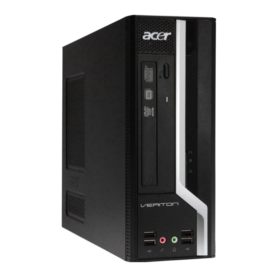
System Components This section is a virtual tour of the system’s interior and exterior components. Front Panel Component Acer logo Optical drive button ODD activity indicator Optical drive USB 2.0 ports Microphone-in jack Headphone/Speaker-out/line-out jack CF I/II (CompactFlash Type I/II) slot XD(XD-Picture)/SD(Secure Digital)/PRO slot LAN activity indicator HDD activity indicator... -
Page 16: Rear Panel
Rear Panel Component Fan aperture PS2 keyboard connector DVI-D port D-Sub VGA port USB 2.0 ports Microphone jack Line-out jack Expansion slot(graphics card ect.) line-in jack Serial port Parallel port RJ45 LAN port Serial port PS2 mouse connector Power connector Chapter 1... -
Page 17: Hardware Specifications And Configurations
Hardware Specifications and Configurations Processor Item Specification Processor Type Intel Sandy Bridge Processor Socket Type Intel Socket LGA 1155 pin 1333 MHz Minimum operating speed 0 MHz (If Stop CPU Clock in Sleep State in BIOS Setup is set to Enabled.) BIOS Item Specification... -
Page 18: Memory Combinations
Memory Combinations Slot Memory Total Memory Slot 1 1GB/2GB/4GB 1G ~4GB Slot 2 1GB/2GB/4GB 1G ~4GB Slot 3 1GB/2GB/4GB 1G ~4GB Slot 4 1GB/2GB/4GB 1G ~4GB Maximum System Memory Supported 1G~16GB System Memory Item Specification Memory slot number 4 slot Support Memory size per socket 1GB/2GB/4GB Support memory type... -
Page 19: Sata Interface
SATA Interface Item Specification SATA controller Intel Q65 Number of SATA channel SATA X4(6Gb/s*2SATAIII and 3Gb/s*2SATAII) Support mode RAID/AHCI/IDE mode option USB Port Item Specification Universal HCI USB 2.0/1.1 USB Class Support legacy keyboard for legacy mode USB Connectors Quantity Ports Quantity: 14 6 back rear ports(USB2.0 * 6 ports) •... -
Page 20: Power Management Function(Acpi Support Function)
Power Management Function(ACPI support function) Device Standby Mode Independent power management timer for hard disk drive devices(0-15 minutes,time step=1minute). • Hard Disk drive goes into Standby mode(for ATA standard interface). • Disable V-sync to control the VESA DPMS monitor. • Resume method:device activated (keyboard for DOS, keyboard &mouse for Windows. -
Page 21: System Utilities
Chapter 2 System Utilities CMOS Setup Utility CMOS setup is a hardware configuration program built into the system ROM, called the complementary metal- oxide semiconductor (CMOS) Setup Utility. Since most systems are already properly configured and optimized, there is no need to run this utility. You will need to run this utility under the following conditions. When changing the system configuration settings •... -
Page 22: Entering Cmos Setup
Entering CMOS setup Turn on the server and the monitor. If the server is already turned on, close all open applications, then restart the server. During POST, press Delete. If you fail to press Delete before POST is completed, you will need to restart the server. The Setup Main menu will be displayed showing the Setup’s menu bar. -
Page 23: Main
Main The Setup Main menu includes the following main setup categories. Parameter Description System BIOS Version Version number of the BIOS setup utility. Build Date Date when the BIOS setup utility was built Processor Type of CPU installed on the system. Core Frequency Core speed of the CPU installed on the system. - Page 24 Advanced Parameter Description Miscellaneous Press Enter to access the Miscellaneous submenu Advanced Chipset Configuration Press Enter to access the Advanced Chipset Configuration submenu Integrated Peripherals Press Enter to access the Integrated Peripherals submenu PC Health Status Press Enter to access the PC Health Status submenu Chapter 2...
- Page 25 Miscellaneous Parameter Description Option AHCI Port1/3/4 Displays the status of auto detection of the AHCI device. Clock to All DIMM/ This item allows you to enable or disable the Clock to all DIMM/PCI/PCIE. Enabled PCI/PCIE Disabled Spread Spectrum If you enable spread spertrum, it can significantly reduce the EMI (Electro- Enabled Magneticinterface) generated by the system and voltage according to its Disabled...
-
Page 26: Advanced Chipset Configuration
Advanced Chipset Configuration Intel EIST This item allows users to enable or disable the EIST (Enhanced Intel Enabled SpeedStep technology). Disabled Intel Turbo Boost This item allows users to enable or disable the Intel Turbo Boost. Enabled Disabled Intel AES-NI Enables or disables Advanced Encryption Standard New Instructions Enabled (AES-NI). -
Page 27: Integrated Peripherals
Integrated Peripherals Parameter Description Option Onboard SATA Controller Enables or disables the onboard SATA controller. Enabled Disabled Onboard SATA Mode Select an operating mode for the onboard SATA. Native IDE AHCI Onboard USB Controller Enables or disables the onboard USB controller. Enabled Disabled Legacy USB Support... - Page 28 Parameter Description Option Parallel Port Address Use this item to enable or disable the onboard COM2 serial port, and to Disabled assign a portaddress. Parallel Port Mode Use this item to select the parallel port mode. You can select Normal Normal (StandardParallel Port), ECP (Extended Capabilities Port), EPP (Enhanced Parallel Port), orBpp (Bi-Directional Parallel Port).
-
Page 29: Pc Health Status
PC Health Status Parameter Description Option System Shutdown This item enables or disables you to set the shutdown temperature of Enabled Temperature the system. Disabled CPU Shutdown Temperature This item enables or disables you to set the shutdown temperature of Enabled the CPU. - Page 30 Power Parameter Description Option ACPI Suspend Mode Select an ACPI state. S3 (STR) S1 (POS) Deep Power Off Mode Select the Deep power off Mode Enabled Disabled Power On by RTC Alarm Enables or Disables to wake up the system by RTC Alarm Function Enabled Disabled Power On by PCIE Devices...
- Page 31 Security Parameter Description Option Supervisor Password This item indicates whether a supervisor password has been set. If the password has been installed, Installed displays. If not, Not Installed displays. User Password This item allows you to change user password. HDD Password This item indicates whether a HDD password has been set.
- Page 32 Setting a supervisor password Use the up/down arrow keys to select Change Supervisor Password menu then press Enter. A password box will appear. Type a password then press Enter. The password may consist up to six alphanumeric characters (A-Z, a-z, 0-9) Retype the password to verify the first entry then press Enter again.
-
Page 33: Boot Options
Boot Options 1st/2nd/3rd/4th/5th Boot Specifies the boot order from the available devices. Device Hard Disk CD^DVD Removable Device EFI Device Priority Press Enter to access the EFI Device Priority submenu and specify the boot device priority sequence from available EFI devices. Hard Disk Drive Priority Press Enter to access the Hard Disk Drive Priority submenu and specify the boot device priority sequence from available hard drives. - Page 34 Exit Parameter Description Save & Exit Setup When you have completed the system configuration changes, select this option to leave the BIOS Setup Utility and reboot the computer, so the new system configuration parameters can Save & Exit Setup Enter take effect.
-
Page 35: System Disassembly And Assembly
Chapter 3 System Disassembly and Assembly This chapter contains step-by-step procedures on how to disassemble and assembly the desktop computer for maintenance and troubleshooting. Disassembly Requirements To disassemble the computer, you need the following tools: Wrist grounding strap and conductive mat for preventing electrostatic discharge •... -
Page 36: Pre-Disassembly Procedure
Pre-disassembly Procedure Before proceeding with the disassembly procedure, perform the steps listed below: Turn off the system and all the peripherals connected to it. Unplug the power cord from the power outlets. Unplug the power cord from the system. Unplug all peripheral cables from the system. Place the system unit on a flat, stable surface. -
Page 37: Removing The Side Panel
Removing the Side Panel Remove the three screws located on the rear edge of the side panel. Slide the side panel toward the back of the chassis until the tabs on the cover disengage with the slots on the chassis. Lift the side panel away from the server and put it aside for reinstallation later. -
Page 38: Removing The Front Bezel
Removing the Front Bezel Release the front bezel from the chassis interior. Pull the bezel away from the chassis. Chapter 3... -
Page 39: Removing The Heat Sink Fan Assembly
Removing the Heat Sink Fan Assembly WARNING:The heat sink becomes very hot when the system is on. NEVER touch the heat sink with any metal or with your hands. Use a long-nosed screwdriver to loosen the four screws on the heat sink, in the order as shown below. Note :CPU Fan has been highlighted with the yellow circle as above image shows.Please detach the CPU Fan and follow local regulations for disposal. - Page 40 Lay down the heat sink fan assembly, in an upright position, on top of the optical drive, as shown below, then disconnect the fan cable from the mainboard. Remove the heat sink fan assembly from the chassis then lay it down in an upright position—with the thermal patch facing upward.
-
Page 41: Removing The Processor
Removing the Processor IMPORTANT:Before removing a processor from the mainboard, make sure to create a backup file of all important data. Release the load lever(1). Lift the load lever and load plate to the fully open, upright position (2) and (3). Chapter 3... - Page 42 Pull out the processor from the socket. IMPORTANT: If you are going to install a new processor, note the arrow on the corner to make sure the processor is properly oriented over the socket. Chapter 3...
-
Page 43: Removing The Wireless Lan Card
Removing the Wireless LAN Card Remove the two screws that secures the card to the chassis. Lift the guard card hook to the fully open. Gently pull the card to remove it from the mainboard. Note: Circuit boards >10 cm² has been highlighted with the yellow rectangle as above image shows. Please detach the Circuit boards and follow local regulations for disposal. -
Page 44: Removing The Vga Card
Removing the VGA Card Gently pull the card to remove it from the mainboard. Note: Circuit boards >10 cm² has been highlighted with the yellow rectangle as above image shows. Please detach the Circuit boards and follow local regulations for disposal. Chapter 3... -
Page 45: Removing The Memory Modules
Removing the Memory Modules IMPORTANT:Before removing any DIMM from the memory board, make sure to create a backup file of all important data. Press the holding clips on both sides of the DIMM slot outward to release the DIMM(1). Gently pull the DIMM upward to pull it away from the M/B(2). Note: Circuit boards >10 cm²... -
Page 46: Removing The Optical Drive
Removing the Optical Drive Disconnect the data and power cables from the rear of the optical drive. Slide lock handle toward the right until the lock handle no removing as show below. Pull the drive out of the drive bay. Chapter 3... -
Page 47: Removing The Hard Disk Drive
Removing the Hard Disk Drive Disconnect the data and power cables from the rear of the hard drive. Use two fingers to press the HDD bracket then pull the bracket up. Take out the HDD module. Use a hand to open out the HDD bracket until the hook of HDD bracket away from the HDD screw bore. - Page 48 Remove the HDD-ODD bracket. Remove the screw that secures the HDD bracket to the chassis. Remove the two screws from chassis. Lift the bracket up and turn it over. Chapter 3...
- Page 49 Release the HDD data cables away from Chassis clip. Disconnect the other end of the HDD data cable and ODD data cable from the mainboard. Chapter 3...
-
Page 50: Removing The Com Port Cable And Printer Port Cable
Removing the COM2 Port Cable and Printer Port Cable Remove the COM2 port cable. Disconnect the COM2 port cable from motherboard. Remove the two screws as below shown. Pull the COM2 port cable form the chassis. Chapter 3... - Page 51 Remove the printer port cable. Disconnect the printer port cable from motherboard. Remove the two screws according to the following picture. Pull the printer port cable from the chassis. Chapter 3...
-
Page 52: Removing The Power Supply
Removing the Power Supply Disconnect the 4-pin and 24-pin power supply cables from the mainboard. Remove the screw that secures the power supply to the chassis. Chapter 3... - Page 53 Remove the two screws that secure the power supply to the rear panel. Lift the power supply module out of the chassis. Chapter 3...
-
Page 54: Removing The Internal Speaker
Removing the Internal Speaker Open the cable clip, then release the audio cable and internal speaker cable. Disconnect the internal speaker cables from the mainboard. Remove the screw that secure the internal speaker to the chassis. Chapter 3... - Page 55 Take the speaker out of chassis. Chapter 3...
-
Page 56: Removing The Mainboard
Removing the Mainboard Open the cable retention clip,then take out these cables. Disconnect the card reader cable and front USB cable from the mainboard. Disconnect the Front panel cable, OBR cable,chassis intrusion alarm cable and front audio cable from the mainboard. - Page 57 Remove the cable cilp from the chassis. Remove the six screws that secure the mainboard to the chassis. Note: Circuit boards >10 cm² has been highlighted with the yellow rectangle as above image shows. Please detach the Circuit boards and follow local regulations for disposal. Chapter 3...
- Page 58 Lift the board from the chassis. Punching in IO Shield then you can remove it. Remove the RTC battery. Note:RTC battery has been highlighted with the yellow circle as above image shows.Please detach the RTC battery and follow local regulations for disposal. Chapter 3...
-
Page 59: Removing The Intrusion Alarm Cable Assembly
Removing the Intrusion Alarm Cable Assemby Removing the two screws from the chassis. Release the intrusion alarm assembly from the chassis. Chapter 3... -
Page 60: Removing The Power Switch,Obr And Led Cable Assembly
Removing the Power Switch,OBR and LED Cable Assembly Release these cables away from Chassis clip. Release the locking tabs from the chassis interior(1),then Pull the OBR and LED cable assembly from the chassis(2). Chapter 3... - Page 61 Release the cable away from Chassis clip. Release the locking tabs from the chassis interior(1) and Pull the power button assembly from the chassis(2). Chapter 3...
-
Page 62: Removing The Front I/O And Card Reader Boards
Removing the Front I/O and Card Reader Boards Removing the screw from chassis. Pull the front I/O and USB assembly from chassis. Remove the card reader board. Remove the two screws that secure the card reader board to the bracket. Chapter 3... - Page 63 Pull the card reader board out of the bracket. Remove the front I/O board. Remove the two screws that secure the I/O board to the bracket. Pull the I/O board out of the bracket. Chapter 3...
-
Page 64: Assembly Requirements
Assembly Requirements To assemble the computer, you need the following tools: Wrist grounding strap and conductive mat for preventing electrostatic discharge • Flat-blade screwdriver • Philips screwdriver • Hex screwdriver • Plastic flat-blade screwdriver • Plastic tweezers • NOTE: The screws for the different components vary in size. During the assembly process, group the screws with the corresponding components to avoid mismatch when putting back the components. -
Page 65: Assembly Procedure
Assembly Procedure Before proceeding with the assembly procedure, perform the steps listed below: Turn off the system and all the peripherals connected to it. Unplug the power cord from the power outlets. Unplug the power cord from the system. Unplug all peripheral cables from the system. Place the system unit on a flat, stable surface. -
Page 66: Install The Processor
Install the Processor Release the load lever. Lift the load lever and load plate to the fully open,then take out the CPU cover. Put the CPU in the seat and close the load plate and load lever. NOTE: When you install the processor, note the arrow on the corner to make sure the processor is properly oriented over the socket. -
Page 67: Install The Heat Sink Fan Assembly
Install the Heat Sink Fan Assembly Use a long-nosed screwdriver to fix the four screws on the heat sink, in the order as shown below. Connect the fan cable to the mainboard. Chapter 3... -
Page 68: Install The Memory
Install the Memory Open the holding clips on both sides of the DIMM slot outward. Press down the memory. IMPORTANT:pls refer to below installing memory rule. DIMM1 DIMM2 DIMM3 DIMM4 Remark:A and B show different size of memory, size:A>B Chapter 3... -
Page 69: Romoving The Side Panel
Removing the Side Panel Remove the four screws located on the rear edge of the side panel. Slide the side panel toward the back of the chassis until the tabs on the cover disengage with the slots on the chassis. Lift the side panel away from the server and put it aside for reinstallation later. -
Page 70: Romoving The Front Bezel And The Odd Bracket
Remove the Front Bezel and the ODD Bracket Remove the front panel.(Refer to “Removing the Front Bezel” on page 30) Remove the ODD bracket. Remove the screw. Remove the two screws. Pull the ODD bracket from the chassis. Chapter 3... -
Page 71: Romoving The Outside Connector Slice
Remove Outside Connect Slice Punching in PCI Shelf slice then you can remove it. At the same time, punching in the COM2 port and print cover on rear plate of the chassis then you can remove it. Install the I/O Shielding Install I/O shielding into chassis. -
Page 72: Install The Main Board
Install the Main Board Put M/B in the chassis aligning the M/B I/O connector with I/O shielding. Fix1~ 8 pcs screws into the corresponding hole. NOTE: Make sure the I/O spring touching M/B after installing. Chapter 3... -
Page 73: Install The Internal Speaker
Install the Internal Speaker Insert hook of one end internal speaker into chassis, then fix the screw of other end internal speaker. Connect the cable of internal speaker to main board. Chapter 3... -
Page 74: Connect The Cable
Connect the Cable Paste the clip to Bottom of chassis. Connect the ATX 24Pin Power cable and ATX 4Pin Power cable to main board. Connector the card reader USB cable/front USB cable/HDD data cable/ODD data cable/intrusion cable to motherboard. Chapter 3... - Page 75 Connector the front panel/front Audio cable/OBR cable to motherboard. Use chassis cable clip to fix front USB cable &front panel cable &audio cable & card reader USB & HDD data cables(1), then use cable clip to fix front audio cable and internal speaker cable. Let HDD SATA data cable pass through the three chassis clips.
-
Page 76: Install The Optical Drive Bracket
Install the Optica Drive Bracket Install down the optica drive bracket. Fix the two screws. Fix the screw. Chapter 3... -
Page 77: Install The Hard Disk Drive
Install the Hard Disk Drive Take out HDD bracket from chassis, Hook of HDD bracket as shonw below. Open out the HDD bracket, install the HDD. NOTE: The hook of HDD bracket must level at both sides screw bore of HDD. Install the HDD into the bracket. - Page 78 Connect the data cable and power cable to the rear of the hard disk drive. Chapter 3...
-
Page 79: Install The Optical Drive
Install the Optica Drive When prepare to install the optica drive, check the Lock handle whether open state. if not, open the Lock handle. Install the ODD into the bracket. Chapter 3... - Page 80 Close the Lock handle. Connect the power cables and data cable to the rear of the optical drive. Chapter 3...
-
Page 81: Install The Vga Card
Install the VGA Card Lift the guard card hook to the fully open. Open the VGA card latch, then press down the VGA card. Chapter 3... -
Page 82: Install The Wireless Lan Card
Install the Wireless LAN Card Press down the wireless Lan card. Close the guard card hook, then fix the two screws. Chapter 3... -
Page 83: Install The Printer Port Cable And Com2 Port Cable
Install the the Printer Port and COM Port Cable Cable Install the printer port cable. Push the printer port cable to the chassis. Ffix the two screws according to the following picture. Connect the printer port cable to motherboard. Chapter 3... - Page 84 Install the COM port cable. Push the COM port cable to chassis. Fix the two screws as shown below. Connect the COM port cable to main board. Chapter 3...
-
Page 85: Install The Front Bezel
Install the Front Bezel Install the panel onto chassis and then check if it is Installed OK. Chapter 3... -
Page 86: Install The Side Panel
Install the Lift Side Panel Install the side Panel, then fix two Screws. Chapter 3... -
Page 87: System Troubleshooting
Chapter 4 System Troubleshooting This chapter provides instructions on how to troubleshoot system hardware problems. Hardware Diagnostic Procedure IMPORTANT:The diagnostic tests described in this chapter are only intended to test Acer products. Non- Acerproducts, prototype cards, or modified options can give false errors and invalid systemresponses. -
Page 88: System Check Procedures
System Check Procedures Power System Check If the system will power on, skip this section. Refer to System External Inspection. If the system will not power on, do the following: Check if the power cable is properly connected to the system and AC source. •... -
Page 89: Beep Codes
Beep Codes Beep codes are used by the BIOS to indicate a serious or fatal error to the end user. Beep codes are used when an error occurs before the system video has been initialized. Beep codes will be generated by the system board speaker, commonly referred to as the PC speaker. -
Page 90: Checkpoints
Checkpoints A checkpoint is either a byte or word value output to I/O port 80h.The BIOS outputs checkpoints throughout bootblock and Power-On Self Test (POST) to indicate the task the system is currently executing. Checkpoint sare very useful in aiding software developers or technicians in debugging problems that occur during the pre- boot process. - Page 91 Checkpoint Description Restore CPUID value back into register. Give control to BIOS POST (ExecutePOSTKernel). See POST Code Checkpoints section of document for more information. System is waking from ACPI S3 state. E1-E8 EC- OEM memory detection/configuration error. This range is reserved for chipset vendors & system manufacturers.
-
Page 92: Bootblock Recovery Code Checkpoints
Bootblock Recovery Code Checkpoints The Bootblock recovery code gets control when the BIOS determines that a BIOS recovery needs to occur because the user has forced the update or the BIOS checksum is corrupt. The following table describes the type of checkpoints that may occur during the Bootblock recovery portion of the BIOS. NOTE: Checkpoints may differ between different platforms based on system configuration. -
Page 93: Bios Recovery
BIOS Recovery AMIBIOS supports a "recovery flash" mode, which can be used to flash update a BIOS from the boot block. This is used to update a BIOS image without the need to boot to an operating system. The following is the process that user should follow to flash BIOS ROM. -
Page 94: Jumper And Connector Information
Chapter 5 Jumper and Connector Information M/B Placement Chapter 5... - Page 95 LABEL COMPONENTS LGA1155 socket for Intel® Sandy Bridge processor family SYS_FAN System cooling fan connector CPU_FAN CPU cooling fan connector DIMM1~4 240-Pin DDR3 SDRAM slots (Channel A: DIMM4, DIMM2 Channel B: DIMM3, DIMM1) ATX_POWER Standard 24-pin ATX power connector F_USB3 Front panel USB header (card reader) F_USB1~2,4 Front panel USB headers...
-
Page 96: Jumper Setting
Jumper Setting The section explains how to set jumper for correct configuration of the mainboard. Setting Jumper Use the motherboard jumpers to set system configuration options. Jumpers with more Than one pin are numbered. When setting the jumpers, ensure that the jumper caps are Placed on the correct pins. The illustrations show a 2-pin jumper. -
Page 97: Jumper Settings
Jumper Settings Jumper Type Description Setting (default) CLR_CMOS 3-pin CLEAR CMOS 1-2: NORMAL 2-3: CLEAR Before clearing the CLR_CMOS CMOS, make sure to turn the system off. ME_DISABLE 3-pin Disable ME 1-2: NORMAL 2-3: ME disable BIOS_WP 3-pin BIOS Flash 1-2: BIOS_WP protect 2-3: NORMAL... -
Page 98: Checking Connector
Checking Connector Connecting Optional Devices F_AUDIO: Front Panel Audio heade This header allows the user to install auxiliary front-oriented microphone and line-out ports for easier access. Signal Name Signal Name PORT-F_L AUGND PORT-F_R AUD_FP_DET PORT-E_R F_R_A SenseB PORT -E_L F_L_A Chapter 5... - Page 99 SATA1: Serial ATA connectors These connectors are used to support the Serial ATA devices for the highest datatransfer rates (6.0 Gb/s), simpler disk drive cabling and easier PC assembly. It doubles the transfer rate of current SATA 3.0Gb/s interface. Signal Name Signal Name Ground Ground...
- Page 100 SPDIFO: SPDIF out header This is an optional header that provides an SPDIFO (Sony/Philips Digital Interface)output to digital multimedia device through optical fiber or coaxial connector. Signal Name SPDIFOUT COM2: Onboard serial port header Connect a serial port extension bracket to this header to add a second serial port to your system Signal Name Function...
- Page 101 Connecting Case Components CPU_FAN: CPU cooling FAN Power Connector Signal Name Function System Ground +12V Power +12V Sense Sensor Control CPU FAN control SYS_FAN: System Cooling FAN Power Connector Signal Name Function System Ground +12V Power +12V Sense Sensor Chapter 5...
- Page 102 ATX_ POWER: ATX 24-pin Power Connector Signal Name Signal Name +3.3V +3.3V +3.3V -12V PS_ON PWR OK +5VSB +12V +12V +3.3V ATX12V: ATX 12V Power Connector Signal Name Ground Ground +12V +12V SPK: Internal speaker Signal Name Signal Name Output_L Output_R Ground Chapter 5...
- Page 103 Front Panel Header The front panel header (F_PANEL) provides a standard set of switch and LED headers commonly found on ATX or micro-ATX cases. Refer to the table below for information: Signal Function Signal Function GLED0 MSG LED HDD_LED Hard disk LED GLED1 MSG LED Ground...
-
Page 104: Fru (Field Replaceable Unit) List
Chapter 6 FRU (Field Replaceable Unit) List This chapter offers the FRU (Field Replaceable Unit) list in global configuration of the Veriton X4610/Veriton X4610G/Veriton X4618G desktop computer. Refer to this chapter whenever ordering the parts to repair or for RMA (Return Merchandise Authorization). NOTES: When ordering FRU parts, check the most up-to-date information available on your regional web •... -
Page 105: Veriton X4610/X4610G/X4618G Exploded Diagram
Veriton X4610/X4610G/X4618G Exploded Diagram This section will be updated when more information becomes available. NOTE: ITEM NAME Q’TY ITEM NAME Q’TY CHASSIS BEZEL TOP-PANEL Card reader PCB MODULE POWER SUPPLY HDD-SWITCH-HOLDER MOTHER BOARD SWITCH HOLDER ODD-HDD-BRAKET MODULE INTRUSSION-SWITCH LINE-CLIP RUBBER FOOT CD-ROM HDD MODULE USB PLATE... -
Page 106: Veriton X4610/X4610G/X4618G Fru List
Veriton X4610/X4610G/X4618G FRU List Exploded Category Description Part Number Diagram Item MB Kit MB Kit VX4610 Intel Q65 Intel 82579LM Acer Logo MB.VCW07.00 uATX W/ IO Bracket W/O 1394 V1.0 LF Chassis Chassis HX092E xSFF, IO-shielding design; HS.13100.170 Option:COM2/LPT; for Veriton Bezel XSFF BEZEL for New Veriton X Serial w/o CR PZ.11900.141... - Page 107 Exploded Category Description Part Number Diagram Item M378B5773CH0-CH9 256*8 46nm KN.2GB0B.029 NT2GC64B88B0NF-CG 256*8 50nm KN.2GB03.022 ACR256X64D3U1333C9 LF 128*8 0.07um KN.2GB07.002 AD63I1B1624EU KN.2GB0C.007 Memory SAMSUNG SO-DIMM DDRIII 1333 4GB KN.4GB0B.010 M471B5273CH0-CH9 LF 256*8 46nm "HDD HGST 3.5"" 7200rpm 160GB KH.16007.027 HDS721016CLA382 ( Jupiter) SATA II 8MB LF F/ W:3EA"...
- Page 108 Exploded Category Description Part Number Diagram Item HDD SEAGATE 3.5" 7200rpm 1000GB KH.01K01.016 ST31000524AS(Pharaoh 6G) SATA III 32MB LF F/ W:JC45 "HDD WD 3.5"" 5400rpm 1500GB WD15EADS- KH.15K08.001 22P8B0 ( GP500 ) SATA 32MB LF F/W:01.00A01" HDD WD 3.5" 7200rpm 320GB WD3200AAKX- KH.32008.023 221CA0(XL500-1D 6G) SATA III 16MB LF F/ W:15.01H15...
- Page 109 Exploded Category Description Part Number Diagram Item 81D685-469018 NV G315 512MB (64BIT) DDR3 VG.ECS31.5L2 DVI HDMI LP BRACKET ROHS (Samsung) AMD RADEON HD5450 512MB (64BIT) DDR3 VG.ECS54.511 DVI HDMI VGA LP BRACKET ROHS Modem D-1156E#/A10A (Low-profile), Modem PCI-Ex1 FX.10100.003 card, LSI Universal Modem (PCI-E) 56K V.92 - Concorde (C40) VD56UL, Modem USB dongle 56K modem W/O FX.10100.023...
- Page 110 Exploded Category Description Part Number Diagram Item PSU DELTA DPS-220UB-5A 220W Active PFC PY.22009.011 100-127V/220-240V "CPB09-D220E (FR 220W, ES)" PY.2200F.006 Printer port cable Printer port cable W/O ATX bracket of HX series PA.14000.025 chassis COM2 port cable COM2 port cable W/O ATX bracket of HX series PC.13400.043 chassis USB 3.0 Add-on card...
- Page 111 Exploded Category Description Part Number Diagram Item Primax mouse RF2.4 MORFF9UO black color; MS.11200.078 with receiver(nano dangle)DGRFF9 Lite-on RF2.4 SM-9063B with receiver(nano MS.11200.073 dangle) SD-9080 Primax Optical mouse PS2 MOFGKO MS.11200.082 Logitech Optical mouse PS2 M-S0004-O MS.11200.080 Keyboard Keyboard PRIMAX KBRF36211 RF2.4 104KS KB.RF40P.001 Black US Keyboard PRIMAX KBRF36211 RF2.4 104KS...
- Page 112 Exploded Category Description Part Number Diagram Item Keyboard PRIMAX KBRF36211 RF2.4 105KS KB.RF40P.019 Black Belgium Keyboard PRIMAX KBRF36211 RF2.4 105KS KB.RF40P.020 Black Icelandic Keyboard PRIMAX KBRF36211 RF2.4 105KS KB.RF40P.021 Black Norwegian Keyboard PRIMAX KBRF36211 RF2.4 104KS KB.RF40P.022 Black Hebrew Keyboard PRIMAX KBRF36211 RF2.4 105KS KB.RF40P.023 Black Polish Keyboard PRIMAX KBRF36211 RF2.4 105KS...
- Page 113 Exploded Category Description Part Number Diagram Item Keyboard PRIMAX KBRF36211 RF2.4 106KS KB.RF40P.041 Black Korean Keyboard PRIMAX KBRF36211 RF2.4 105KS KB.RF40P.083 Black Spanish Latin Keyboard LITE-ON SK-9660B RF2.4 104KS Black KB.RF40B.042 Keyboard LITE-ON SK-9660B RF2.4 104KS Black KB.RF40B.043 Traditional Chinese Keyboard LITE-ON SK-9660B RF2.4 104KS Black KB.RF40B.044 Simplified Chinese...
- Page 114 Exploded Category Description Part Number Diagram Item Keyboard LITE-ON SK-9660B RF2.4 105KS Black KB.RF40B.062 Norwegian Keyboard LITE-ON SK-9660B RF2.4 104KS Black KB.RF40B.063 Hebrew Keyboard LITE-ON SK-9660B RF2.4 105KS Black KB.RF40B.064 Polish Keyboard LITE-ON SK-9660B RF2.4 105KS Black KB.RF40B.065 Slovenian Keyboard LITE-ON SK-9660B RF2.4 105KS Black KB.RF40B.066 Slovak Keyboard LITE-ON SK-9660B RF2.4 104KS Black...
- Page 115 Exploded Category Description Part Number Diagram Item Keyboard PRIMAX PR1101U USB 104KS Black KB.USB0P.085 Keyboard PRIMAX PR1101U USB 104KS Black KB.USB0P.086 Chinese Keyboard PRIMAX PR1101U USB 104KS Black KB.USB0P.087 Simplified Chinese Keyboard PRIMAX PR1101U USB 104KS Black KB.USB0P.088 US International Keyboard PRIMAX PR1101U USB 104KS Black KB.USB0P.089 Arabic/English...
- Page 116 Exploded Category Description Part Number Diagram Item Keyboard PRIMAX PR1101U USB 105KS Black KB.USB0P.107 Slovenian Keyboard PRIMAX PR1101U USB 105KS Black KB.USB0P.108 Slovak Keyboard PRIMAX PR1101U USB 104KS Black KB.USB0P.109 Russian Keyboard PRIMAX PR1101U USB 105KS Black KB.USB0P.110 Hungarian Keyboard PRIMAX PR1101U USB 104KS Black KB.USB0P.111 Greek Keyboard PRIMAX PR1101U USB 105KS Black...
- Page 117 Exploded Category Description Part Number Diagram Item Keyboard PRIMAX PR1101 PS/2 104KS Black KB.PS20P.120 Arabic/English Keyboard PRIMAX PR1101 PS/2 104KS Black KB.PS20P.121 Thailand Keyboard PRIMAX PR1101 PS/2 104KS Black KB.PS20P.122 Spanish Keyboard PRIMAX PR1101 PS/2 105KS Black KB.PS20P.123 Portuguese Keyboard PRIMAX PR1101 PS/2 107KS Black KB.PS20P.124 Brazilian Portuguese Keyboard PRIMAX PR1101 PS/2 109KS Black...
- Page 118 Exploded Category Description Part Number Diagram Item Keyboard PRIMAX PR1101 PS/2 105KS Black KB.PS20P.143 Danish Keyboard PRIMAX PR1101 PS/2 104KS Black KB.PS20P.144 Czech Keyboard PRIMAX PR1101 PS/2 105KS Black KB.PS20P.145 Romanian Keyboard PRIMAX PR1101 PS/2 105KS Black KB.PS20P.146 Turkish Keyboard PRIMAX PR1101 PS/2 105KS Black KB.PS20P.147 Turkish-Q Keyboard PRIMAX PR1101 PS/2 105KS Black...