Table of Contents
Advertisement
Quick Links
Download this manual
See also:
Configuration Manual
Advertisement
Chapters
Table of Contents

Related Manuals for Asus RS700-X7/PS4


Summary of Contents for Asus RS700-X7/PS4
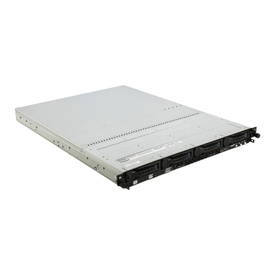
- Page 1 RS700-X7/PS4 1U Rackmount Server User Guide...
- Page 2 ASUSTeK COMPUTER INC. (“ASUS”). ASUS provides this manual “as is” without warranty of any kind, either express or implied, including but not limited to the implied warranties or conditions of merchantability or fitness for a particular purpose. In no...
-
Page 3: Table Of Contents
Installing an expansion card to the riser card bracket ... 2-14 2.5.2 Configuring an expansion card ........2-16 Cable connections ..............2-17 SATA/SAS backplane cabling ........... 2-18 Removable/optional components ..........2-19 2.8.1 System fans ..............2-19 2.8.2 Installing ASUS PIKE RAID card (optional) ....2-20... - Page 4 Internal connectors ..............4-8 Internal LEDs ................4-19 Chapter 5: BIOS setup Managing and updating your BIOS ..........5-2 5.1.1 ASUS CrashFree BIOS 3 utility ........5-2 5.1.2 ASUS EZ Flash Utility ............. 5-3 5.1.3 BUPDATER utility............5-4 BIOS setup program ..............5-6 5.2.1...
- Page 5 Contents 5.4.8 USB Configuration ............5-26 5.4.9 Trusted Computing ............5-27 5.4.10 ACPI Settings ..............5-28 5.4.11 WHEA Configuration ............. 5-28 5.4.12 APM setting ..............5-29 5.4.13 Serial Port Console Redirection ........5-30 5.4.14 Onboard LAN Configuration .......... 5-33 5.4.15 ME Subsystem ..............
- Page 6 WG82574L Gigabit Adapters Driver installation .... 7-28 ® Management applications and utilitiesinstallation ....7-32 7.8.1 Running the support DVD ..........7-32 7.8.2 Drivers menu ..............7-32 7.8.3 Utilities menu ..............7-33 7.8.4 Make disk menu ............7-33 7.8.5 Contact information ............7-33 ASUS contact information ...............A-1...
-
Page 7: Notices
Notices Federal Communications Commission Statement This device complies with Part 15 of the FCC Rules. Operation is subject to the following two conditions: • This device may not cause harmful interference, and • This device must accept any interference received including interference that may cause undesired operation. -
Page 8: Safety Information
Safety information Electrical Safety • Before installing or removing signal cables, ensure that the power cables for the system unit and all attached devices are unplugged. • To prevent electrical shock hazard, disconnect the power cable from the electrical outlet before relocating the system. •... -
Page 9: About This Guide
About this guide Audience This user guide is intended for system integrators, and experienced users with at least basic knowledge of configuring a server. Contents This guide contains the following parts: Chapter 1: Product introduction This chapter describes the general features of the server, including sections on front panel and rear panel specifications. - Page 10 Refer to the following sources for additional information, and for product and software updates. ASUS Server Web-based Management (ASWM) user guide This manual tells how to set up and use the proprietary ASUS server management utility. ASUS websites The ASUS websites worldwide provide updated information for all ASUS...
- Page 11 Chapter 1 This chapter describes the general features of the chassis kit. It includes sections on front panel and rear panel specifications.
-
Page 12: Chapter 1: Product Introduction
14 characters such as xxS0xxxxxxxxxx shown as the figure below. With the correct serial number of the product, ASUS Technical Support team members can then offer a quicker and satisfying solution to your problems. -
Page 13: System Specifications
1.3 System specifications The ASUS RS700-X7/PS4 Series is a 1U barebone server system featuring the ASUS Z9PR-D12/4L server board. The server supports Intel ® LGA2011 processors, plus other latest technologies through the chipsets onboard. Model Name RS700-X7/PS4 1 x Socket LGA2011... - Page 14 Out of Band Remote Onboard ASMB6-iKVM for KVM-over-IP support Management Hardware Solution Software ASUS ASWM Enterprise Dimension (HH x WW x DD) 615mm x 444mm x 43.4mm Net Weight Kg (CPU, DRAM & 15 Kg HDD not inclu ded) Power Supply...
-
Page 15: Front Panel Features
The ports for the USB, VGA, and Gigabit LANs do not appear on the rear panel if the motherboards are not present. This port is for ASUS ASMB5-iKVM controller card only. ASUS RS700-X7/PS4... -
Page 16: Internal Features
Internal features The barebone server includes the basic components as shown. Power supply and power PCI Express slot Riser Card ASUS Z9PR-D12/4L server board System fans SAS / SATA backplane (hidden) HDD tray 1—Connect to SATA1 port (SATA 6Gb/s) HDD tray 2—Connect to... -
Page 17: Led Information
2. With ASMB6-iKVM installed: a hardware monitor event is indicated Normal status Location Location switch is pressed (Press the location switch again to turn off) No LAN connection LAN LEDs Blinking LAN is transmitting or receiving data LAN connection is present ASUS RS700-X7/PS4... -
Page 18: Lan (Rj-45) Leds
1.7.2 LAN (RJ-45) LEDs SPEED LED ACT/LINK LED ACT/LINK LED SPEED LED Status Description Status Description No link 10 Mbps connection GREEN Linked ORANGE 100 Mbps connection BLINKING Data activity GREEN 1 Gbps connection 1.7.3 HDD status LED HDD status LED SATA HDD LED Description GREEN This installed Serial ATA HDD is in good condition... - Page 19 Chapter 2 This chapter lists the hardware setup procedures that you have to perform when installing or removing system components.
-
Page 20: Chapter 2: Hardware Setup
Chassis cover Removing the rear cover Loosen the two thumbscrews on the rear panel to release the rear cover from the chassis. Thumbscrews Firmly hold the cover and slide it toward the rear panel for about half an inch until it is disengaged from the chassis. -
Page 21: Central Processing Unit (Cpu)
ASUS shoulders the repair cost only if the damage is shipment/transit-related. • Keep the cap after installing the motherboard. ASUS will process Return Merchandise Authorization (RMA) requests only if the motherboard comes with the cap on the LGA2011 socket. - Page 22 Press the left load lever with your thumb (A), then move it to the left (B) until it is released from the retention tab. Load lever To prevent damage to the socket pins, do not remove the PnP cap unless you are installing a CPU. Slightly lift the load lever in the direction of the arrow.
- Page 23 The CPU fits in only one correct orientation. DO NOT force the CPU into the socket to prevent bending the connectors on the socket and damaging the CPU! Remove the PnP cap (H) from the CPU socket and close the load plate (I). ASUS RS700-X7/PS4...
- Page 24 Push down the right load lever (J), ensuring that the edge of the load plate is fixed by the lever (K). Insert the right load lever under the retention tab. 10. Push down the left load lever (L), and then insert the lever under the retention tab (M).
- Page 25 If so, skip this step. The Thermal Interface Material is toxic and inedible. DO NOT eat it. If it gets into your eyes or touches your skin, wash it off immediately, and seek professional medical help. ASUS RS700-X7/PS4...
-
Page 26: Installing The Cpu Heatsink And Airduct
2.2.2 Installing the CPU heatsink and airduct To install the CPU heatsink Remove the protection sticker on the back of the CPU heatsink. Protection sticker Place the heatsink on top of the installed CPU, ensuring that the four fasteners match the holes on the motherboard. -
Page 27: System Memory
• • • • • *Refer to ASUS Server AVL for latest update. • Start installing the DIMMs from slot A1 and C1 (light blue). • Always install DIMMs with the same CAS latency. For optimum compatibility, it is recommended that you obtain memory modules from the same vendor. - Page 28 2 CPU Configuration 1 DIMMs • 2 DIMMs • • 3 DIMMs • • • 4 DIMMs • • • • 5 DIMMs • • • • • 6 DIMMs • • • • • • 7 DIMMs • • • • •...
-
Page 29: Installing A Dimm
Press the retaining clip outward to unlock the DIMM. Remove the DIMM from the socket. Support the DIMM lightly with your fingers when pressing the retaining clips. The DIMM might get damaged when it flips out with extra force. ASUS RS700-X7/PS4 2-11... -
Page 30: Hard Disk Drives
Hard disk drives The system supports four hot-swap SATA/SAS hard disk drives and two SATAIII hard disk drives*. The hard disk drive installed on the drive tray connects to the motherboard SATA/SAS ports via the SATA/SAS backplane. *Install the two SATAIII hard disk drives to HDD tray 1 and 2. Refer to page 1-6 for details. - Page 31 Push the tray lever until it clicks, and secures the drive tray in place. The drive tray is correctly placed when its front edge aligns with the bay edge. Repeat steps 1 to 6 if you wish to install a second SATA/SAS drive. ASUS RS700-X7/PS4 2-13...
-
Page 32: Expansion Slot
Expansion slot 2.5.1 Installing an expansion card to the riser card bracket The barebone server comes with a riser card bracket. You need to remove the bracket if you want to install PCI Express x8 or x16 expansion cards. To install a PCI Express x8 or x16 card: Firmly hold the riser card bracket, then pull it up to detach it from the PCI Express x16 slot on the... - Page 33 PCI Express x16 slot on the motherboard. Press the riser card bracket until the golden connectors completely fit the slot and the bracket aligns with the rear panel. Connect the cable(s) to the card, if applicable. ASUS RS700-X7/PS4 2-15...
-
Page 34: Configuring An Expansion Card
2.5.2 Configuring an expansion card After installing the expansion card, configure the it by adjusting the software settings. Turn on the system and change the necessary BIOS settings, if any. See Chapter 5 for information on BIOS setup. Assign an IRQ to the card. Refer to the following tables. Install the software drivers for the expansion card. -
Page 35: Cable Connections
System auxiliary panel connector (from motherboard to front I/O board) System panel connector (from motherboard to front I/O board) SAS connectors (for ASUS PIKE only; from motherboard to SATA/SAS backplane) Serial General Purpose Input/Output connectors (SATA: from motherboard SGPIO1 to SATA/SAS backplane SATA_SGPIO_CON1 connector... -
Page 36: Sata/Sas Backplane Cabling
SATA/SAS backplane cabling SAS_SGPIO_CON1 connector* Connects a 8-pin SGPIO_SEL jumper: plug from power pins 1-2 (Onboard) supply pins 2-3 (Add-on card) Connects the data cables Connect the SATAII/SAS HDDs connected to the motherboard * For PIKE RAID solution, ensure to connect SAS_SGPIO_CON1 to support PIKE card SAS RAID function. -
Page 37: Removable/Optional Components
Or you may need to install the optional components into the system. This section tells how to remove/install the following components: System fans ASUS PIKE RAID card (optional) Ensure that the system is turned off before removing any components. 2.8.1... -
Page 38: Installing Asus Pike Raid Card (Optional)
2.8.2 Installing ASUS PIKE RAID card (optional) Follow the steps below to install an optional ASUS RAID card on your motherboard. Locate the PIKE RAID card slot on the motherboard, then remove the screw beside the PIKE1 slot. Align the golden fingers of the... - Page 39 Chapter 3 This chapter describes how to install the optional components and devices into the barebone server.
-
Page 40: Chapter 3: Installation Options
Friction Rail Kit Installation Guide Your friction rail kit package contains: • One pair of rack rails • One pair of fixing latches • 4 latch screws, 4 rail screws and 4 rail washers Rail Washers Rail screws Latch screws Front end Fixing latches Rack rails... - Page 41 Secure the front and rear ends of the rail with two rack screws and washers. Repeat step 3 to 5 to attach the rack rail on the other side of the rack. ASUS RS700-X7/PS4...
- Page 42 When mounting the server to the rack, ensure to include the side knots on the two sides of the server in the rack rail holders, as shown in the right figure. Do not install the rail kit in the following situation: DO NOT place the rail hook on a thick lip DO NOT install the rail to the outer side of of the mounting hole.
- Page 43 Chapter 4 This chapter includes the motherboard layout and brief descriptions of the jumpers and internal connectors.
-
Page 44: Motherboard Layout
Motherboard layout Layout contents Jumpers Page Clear RTC RAM (CLRTC1) VGA controller setting (3-pin VGA_SW1) LAN controller setting (3-pin LAN_SW1, LAN_SW2, LAN_SW3, LAN_SW4) RAID configuration utility selection (3-pin RAID_SEL1) ME firmware force recovery setting (3-pin ME_RCVR1) DDR3 Thermal event setting (3-pin DIMMTRIP1) PMBus 1.2 PSU select jumper (3-pin SMART_PSU1) Chapter 4: Motherboard information... - Page 45 System panel connector (20-1 pin PANEL1) 4-17 Auxiliary panel connector (20-2 pin AUX_PANEL1) 4-18 Internal LEDs Page Standby power LED (SB_PWR1) 4-19 BMC LED (BMC_LED1) 4-19 CATT Error LED (CATERR_LED1) 4-20 Location LED (LOCLED2) 4-20 CPU Warning LED (ERR_CPU1/2) 4-21 ASUS RS700-X7/PS4...
-
Page 46: Jumpers
Jumpers Clear RTC RAM (CLRTC1) This jumper allows you to clear the Real Time Clock (RTC) RAM in CMOS. You can clear the CMOS memory of date, time, and system setup parameters by erasing the CMOS RTC RAM data. The onboard button cell battery powers the RAM data in CMOS, which include system setup information such as system passwords. -
Page 47: Vga Controller Setting (3-Pin Vga_Sw1)
1–2 to activate the VGA feature. LAN controller setting (3-pin LAN_SW1-4) These jumpers allow you to enable or disable the onboard Intel ® 82574L Gigabit LAN controllers. Set to pins 1-2 to activate the Gigabit LAN feature. ASUS RS700-X7/PS4... -
Page 48: Me Firmware Force Recovery Setting (3-Pin Me_Rcvr1)
LSI MegaRAID or Intel RSTe selection jumper (3-pin RAID_SEL1) This jumper allows you to select the PCH SATA RAID mode to use LSI MegaRAID software or Intel Rapid Storage Technology enterprise 3.0 RAID. ® Place the jumper caps over pins 1–2 if you want to use the LSI MegaRAID software RAID Utility (default). -
Page 49: Ddr3 Thermal Event Setting (3-Pin Dimmtrip1)
DDR3 thermal event setting (3-pin DIMMTRIP1) This jumper allows you to enable/disable DDR3 DIMM thermal sensing event pin. PMBus 1.2 PSU select jumper (3-pin SMART_PSU1) This jumper allows you to select PSU PMBus version, Set to pins 1-2 for PMBus, set to pins 2-3 for Others. ASUS RS700-X7/PS4... -
Page 50: Internal Connectors
Internal connectors Serial ATA connectors (SATA 6Gb/s: 7-pin SATA1, SATA2 [Blue]) (SATA 3Gb/s: 7-pin SATA3, SATA4, SATA5, SATA6 [Black]) Supported by the Intel C602-A PCH chipset, these connectors are for the ® Serial ATA signal cables for Serial ATA hard disk drives that allows up to 6Gb/s of data transfer rate. -
Page 51: Sata Connectors - Isas Connectors (7-Pin Isas1, Isas2, Isas3, Isas4 [Gray])
ATA 3.0 Gb/s hard disk drives and optical disk drives via Serial ATA 3.0 Gb/s signal cables. SAS connectors— PSAS connectors (7-pin PSAS1–8 [Light Blue]) Supported by the ASUS PIKE Card, these connectors are for the SAS signal ® cables for SAS hard disk drives that allows up to 6Gb/s of data transfer rate. -
Page 52: Hard Disk Activity Led Connector (4-Pin Hdled1)
Hard disk activity LED connector (4-pin HDLED1) This LED connector is for the storage add-on card cable connected to the SATA or SAS add-on card. The read or write activities of any device connected to the SATA or SAS add-on card causes the front panel LED to light up. -
Page 53: Vga Connector (10-1 Pin Vga_Hdr1)
DO NOT forget to connect the fan cables to the fan connectors. Insufficient air flow inside the system may damage the motherboard components. • These are not jumpers! DO NOT place jumper caps on the fan connectors! • All fans feature the ASUS Fan Speed Control technology. ASUS RS700-X7/PS4 4-11... -
Page 54: Lan Led Connector (Lan34_Led1)
LAN LED connector (LAN34_LED1) This LED connector supports LAN3 and LAN4 LEDs. The LAN LEDs function only when the motherboard is installed in a server system. 4-12 Chapter 4: Motherboard information... -
Page 55: (8-1 Pin Psgpio1/2, Isgpio1, Sgpio1)
The SGPIO 1 connectors are used for the Intel Rapid Storage Technology Enterprise SGPIO interface that controls the LED pattern generation, device information and general purpose data. • The PSGPIO 1/2 connectors are used for PIKE card. • The ISGPIO 1 connector is for SATA connectors—ISAS connectors. ASUS RS700-X7/PS4 4-13... -
Page 56: Serial Port Connectors (10-1 Pin Com1/Com2)
10. Serial port connectors (10-1 pin COM1/COM2) These connectors are for the serial (COM) ports. Connect the serial port module cable to one of these connectors, then install the module to a slot opening at the back of the system chassis. Only COM1 functions when BMC is Enabled. -
Page 57: Eatx Power Connectors (24-Pin Eatxpwr1, 8-Pin Eatx12V1)
• This motherboard supports EATX2.0 PSU or later version. • Ensure that your power supply unit (PSU) can provide at least the minimum power required by your system. ASUS RS700-X7/PS4 4-15... -
Page 58: Power Supply Smbus Connector (5-Pin Psusmb1)
13. Power Supply SMBus connector (5-pin PSUSMB1) This connector allows you to connect SMBus (System Management Bus) to the power supply unit to read PSU information. Devices communicate with an SMBus host and/or other SMBus devices using the SMBus interface. 4-16 Chapter 4: Motherboard information... -
Page 59: System Panel Connector (20-1 Pin Panel1)
BIOS settings. Pressing the power switch for more than four seconds while the system is ON turns the system OFF. Reset button (2-pin RESET) This 2-pin connector is for the chassis-mounted reset button for system reboot without turning off the system power. ASUS RS700-X7/PS4 4-17... -
Page 60: Auxiliary Panel Connector (20-2 Pin Aux_Panel1)
15. Auxiliary panel connector (20-2 pin AUX_PANEL1) This connector is for additional front panel features including front panel SMB, locator LED and switch, chassis intrusion, and LAN LEDs. Front panel SMB (6-1 pin FPSMB) These leads connect the front panel SMBus cable. LAN activity LED (2-pin LAN13_LED, LAN24_LED) These leads are for Gigabit LAN activity LEDs on the front panel. -
Page 61: Internal Leds
LED. Baseboard Management Controller LED (BMC_LED1) The BMC LED works with the ASUS ASMB6 management device and indicates its initiation status. When the PSU is plugged and the system is OFF, ASUS ASMB6 management device starts system initiation for about one (1) minute. -
Page 62: Catt Error Led (Caterr_Led1)
CATT Error LED (CATTERR_LED1) Indicates that the system has experienced a fatal or catastrophic error and cannot continue to operate. Location LED (LOCLED2) This LED allows you to know the server location. 4-20 Chapter 4: Motherboard information... -
Page 63: Cpu Warning Led (Err_Cpu1/2)
CPU warning LED (ERR_CPU1/2) The CPU warning LEDs light up to indicate an impending failure of the corresponding CPU. ASUS RS700-X7/PS4 4-21... - Page 64 4-22 Chapter 4: Motherboard information...
- Page 65 Chapter 5 This chapter tells how to change the system settings through the BIOS Setup menus. Detailed descriptions of the BIOS parameters are also provided.
-
Page 66: Chapter 5: Bios Setup
5.1.1 ASUS CrashFree BIOS 3 utility The ASUS CrashFree BIOS 3 is an auto recovery tool that allows you to restore the BIOS file when it fails or gets corrupted during the updating process. You can update a corrupted BIOS file using a USB flash drive that contains the updated BIOS file. -
Page 67: Asus Ez Flash Utility
5.1.2 ASUS EZ Flash Utility The ASUS EZ Flash Utility feature allows you to update the BIOS without having to use a DOS-based utility. Before you start using this utility, download the latest BIOS from the ASUS website at www.asus.com. -
Page 68: Bupdater Utility
Updating the BIOS file To update the BIOS file using the BUPDATER utility: Visit the ASUS website at www.asus.com and download the latest BIOS file for the motherboard. Save the BIOS file to a bootable USB flash disk drive. Copy the BUPDATER utility (BUPDATER.exe) from the ASUS support website at support.asus.com to the bootable USB flash disk drive you created... - Page 69 DO NOT shut down or reset the system while updating the BIOS to prevent system boot failure! The utility returns to the DOS prompt after the BIOS update process is completed. Reboot the system from the hard disk drive. The BIOS update is finished! Please restart your system. C:\> ASUS RS700-X7/PS4...
-
Page 70: Bios Setup Program
The BIOS setup screens shown in this section are for reference purposes only, and may not exactly match what you see on your screen. • Visit the ASUS website (www.asus.com) to download the latest BIOS file for this motherboard. Chapter 5: BIOS setup... -
Page 71: Bios Menu Screen
For changing the security settings Tool For configuring options for special functions Exit For selecting the exit options To select an item on the menu bar, press the right or left arrow key on the keyboard until the desired item is highlighted. ASUS RS700-X7/PS4... -
Page 72: Menu Items
5.2.3 Menu items The highlighted item on the menu bar displays the specific items for that menu. For example, selecting Main shows the Main menu items. The other items (Event Logs, Advanced, Monitor, Boot, Tool, and Exit) on the menu bar have their respective menu items. -
Page 73: Main Menu
00:E0:18:02:20:DC ESC: Exit Onboard LAN4 MAC: 00:E0:18:02:20:DD Version 2.14.1219. Copyright (C) 2011 American Megatrends, Inc. 5.3.1 System Date [Day xx/xx/xxxx] Allows you to set the system date. 5.3.2 System Time [xx:xx:xx] Allows you to set the system time. ASUS RS700-X7/PS4... -
Page 74: Advanced Menu
Advanced menu The Advanced menu items allow you to change the settings for the CPU and other system devices. Be cautious when changing the settings of the Advanced menu items. Incorrect field values can cause the system to malfunction. Aptio Setup Utility - Copyright (C) 2011 American Megatrends, Inc. Main Advanced Server Mgmt... - Page 75 SuSE Linux 9.2, Redhat Enterprise 3 Update 3). Configuration options: [Disabled] [Enabled] Server Class [Custom] Use Intel recommended prefetch settings. Configuration options: [Enterprise] [High Performance(HPC)] [Custom] Hardware Prefetcher [Enabled] This Item allows you to turn on/off the mid level cache(L2) streamer prefetcher. Configuration options: [Disabled] [Enabled] ASUS RS700-X7/PS4 5-11...
-
Page 76: Cpu Power Management Configuration
Adjacent Cache Line Prefetch [Enabled] This Item allows you to turn on/off prefetching of adjacent cache lines. Configuration options: [Disabled] [Enabled] DCU Streamer Prefetcher [Enabled] This Item allows you to enable/disable L1 data prefetcher. Configuration options: [Disabled] [Enabled] DCU IP Prefetcher [Enabled] This Item allows you to enable/disable L1 data prefetcher. Configuration options: [Disabled] [Enabled] Intel Virtualization Technology [Enabled] When enabled this item, a VMM can utilize the additional hardware capabilities... - Page 77 <+> and <-> keys to adjust the value. Recommended short duration power1 1.2 * Long Duration Short duration power limit Allows you to set short duration power limit in watts. Use the <+> and <-> keys to adjust the value. ASUS RS700-X7/PS4 5-13...
-
Page 78: Chipset Configuration
5.4.3 Chipset Configuration Aptio Setup Utility - Copyright (C) 2011 American Megatrends, Inc. Advanced QPI Configuration Page QPI Configuration Memory Configuration CPU II0 Bridge Configuration PCH Configuration Intel(R) VT for Directed I/O Configuration QPI Configuration Aptio Setup Utility - Copyright (C) 2011 American Megatrends, Inc. Advanced Enable/Disable Isoc Current QPI Link Speed... - Page 79 Channel Interleaving [Auto] Select different channel interleaving setting. Configuration options: [Auto] [1 Way] [2 Way] [3 Way] [4 Way] Rank Interleaving [Auto] Select different rank interleaving setting. Configuration options: [Auto] [1 Way] [2 Way] [4 Way] [8 Way] ASUS RS700-X7/PS4 5-15...
- Page 80 Patrol Scrub [Disabled] Allows you to enable/disable Patrol Scrub. Configuration options: [Disabled] [Enabled] Demand Scrub [Enabled] Allows you to enable/disable demand scrubing feature. Configuration options: [Enabled] [Disabled] Data Scrambling [Enabled] Allows you to enable/disable data scrambling. Configuration options: [Enabled] [Disabled] Device Tagging [Disabled] Allows you to enable/disable device tagging.
-
Page 81: Dimm Information
Configuration options: [Disabled] [Enabled] DCA Support [Enabled] Allows you to enable/disable DCA support. Configuration options: [Disabled] [Enabled] VGA Priority [offboard] Allows you to decide priority between onboard and 1st offboard video device found. Configuration options: [Onboard] [Offboard] ASUS RS700-X7/PS4 5-17... - Page 82 PCH Configuration Aptio Setup Utility - Copyright (C) 2011 American Megatrends, Inc. Advanced Support for PCH Compatibility Name Patsburg Revision ID(CRID) Stepping 06 (C1 Stepping) functionality. SB Chipset Configuration PCH Compatibility RID [Disabled] Deep Sx [Disabled] SCU devices [Enabled] Onboard SATA RAID Oprom [Enabled] High Precision Event Timer Configuration High Precision Timer...
- Page 83 The following item appears only when you set Intel(R) VT-d to [Enabled]. Coherency Support [Disabled] Allows you to enable/disable VT-d Engine Coherency support. Configuration options: [Disabled] [Enabled] ATS Support [Disabled] Allows you to enable/disable VT-d Engine address translation services (ATS) support. Configuration options: [Disabled] [Enabled] ASUS RS700-X7/PS4 5-19...
-
Page 84: Pch Sata Configuration
5.4.4 PCH SATA Configuration Aptio Setup Utility - Copyright (C) 2011 American Megatrends, Inc. Advanced (1)IDE Mode. (2)AHCI Mode. SATA Port1 Not Present (3)RAID Mode. SATA Port2 Not Present SATA Port3 Not Present SATA Port4 Not Present SATA Port5 Not Present SATA Port6 Not Present SATA Mode [AHCI Mode]... -
Page 85: Pch Scu Configuration
Not Present →←: Select Screen Select Item ↑↓: Enter: Select Item +/-: Change Opt. F1: General Help F2: Previous Values F5: Optimized Defaults F10: Save & Exit ESC: Exit Version 2.14.1219. Copyright (C) 2011 American Megatrends, Inc. ASUS RS700-X7/PS4 5-21... -
Page 86: Pci Subsystem Settings
5.4.6 PCI Subsystem Settings Aptio Setup Utility - Copyright (C) 2011 American Megatrends, Inc. Advanced In case of multiple Option PCI Bus Driver Version V 2.05.00 ROMs (Legacy and EFI Compatible), specifies what PCI Option ROM Handling PCI option ROM to lanuch. PCI ROM Priority [EFI Compatible ROM] PCI Common Setting... -
Page 87: Pci Express Settings
Version 2.14.1219. Copyright (C) 2011 American Megatrends, Inc. PCI Express Link Register Settings ASPM Support [Disabled] Allows to set the ASPM level. Configuration options: [Disabled] [Auto] [Force L0s] [Force L0s] Force all links to L0s state. [Auto] BIOS auto configure. [Disabled] Disabled ASPM. ASUS RS700-X7/PS4 5-23... - Page 88 PCIE Slot Option Rom Configuration Aptio Setup Utility - Copyright (C) 2011 American Megatrends, Inc. Advanced Enables or disables boot Legacy 0pROM Support option for legacy mass Launch Storage 0pROM [Enabled] storage device with option ROM. PCIE1 Option Rom [Enabled] PCIE2 Option Rom [Enabled] PCIE3 Option Rom [Enabled] PCIE4 Option Rom...
-
Page 89: Intel Txt(Lt-Sx) Configuration
This is the Intel Trusted Execution Technology (TXT) feature. VT and VT-d support must be enabled before using this feature.. Install a Trusted Platform Module (TPM) on the motherboard to enable the Intel ® TXT(LT) Hardware Support. ASUS RS700-X7/PS4 5-25... -
Page 90: Usb Configuration
5.4.8 USB Configuration Aptio Setup Utility - Copyright (C) 2011 American Megatrends, Inc. Advanced Enabled Legacy USB support. USB Configuration AUTO option disables legacy support if no USB devices USB Devices: are connected. DISABLE 3 Drives, 1 Keyboard, 2 Mice, 3 Hubs option will keep USB devices available only for EFI Legacy USB Support... -
Page 91: Trusted Computing
O.S. will not show Security Device. TCG EFI protocol and INT1A interface will not be Current Status Information available. No Security Device Found TPM Support [Enabled] Allows you to enable or disable the TPM support. Configuration options: [Disabled] [Enabled] ASUS RS700-X7/PS4 5-27... -
Page 92: Acpi Settings
5.4.10 ACPI Settings Aptio Setup Utility - Copyright (C) 2011 American Megatrends, Inc. Advanced Enables or Disables BIOS ACPI ACPI Settings Auto Configuration. Enable ACPI Auto Configuration [Disabled] Enabled Hibernation [Enabled] ACPI Sleep State [S1 (CPU Stop Clock)] Lock Legacy Resources [Disabled] Enable ACPI Auto Configuration [Disabled] Allows you to enable or disable BIOS ACPI Auto Configuration. -
Page 93: Apm Setting
Enables the Ring devices to generate a wake event. Power On By RTC [Disabled] [Disabled] Disables RTC from generating a wake event. When set to [Enabled], the items RTC Alarm Date (Days) and [Enabled] Hour/Minute/Second will become user-configurable with set values. ASUS RS700-X7/PS4 5-29... -
Page 94: Serial Port Console Redirection
5.4.13 Serial Port Console Redirection Aptio Setup Utility - Copyright (C) 2011 American Megatrends, Inc. Advanced Consloe Redirection Enable COM1 or Disable. Console Redirection [Disabled] Console Redirection Settings COM2 Console Redirection [Enabled] Console Redirection Settings Serial Port for Out-of-Band Management/ Windows Emergency Management Services (EMS) Console Redirection [Disabled]... -
Page 95: Console Redirection Settings
Configuration options: [80x24] [80x25] COM2 Console Redirection [Enabled] Enables or disables the console redirection feature. Configuration options: [Disabled] [Enabled] Console Redirection Settings Please refer to the description of the Console Redirection Settings item under COM1 for details. ASUS RS700-X7/PS4 5-31... - Page 96 Serial Port for Out-of-Band Management/ Windows Emergency Management Services (EMS) Console Redirection [Disabled] Enables or disables the console redirection feature. Configuration options: [Disabled] [Enabled] The following item appears only when you set Console Redirection to [Enabled]. Console Redirection Settings Out-of-Band Mgmt Port [COM1] Microsoft Windows Emergency Management Services (EMS) allow for remote management of a Windows Server OS through a serial port.
-
Page 97: Onboard Lan Configuration
Enables or disables Intel LAN3 function. Configuration options: [Disabled] [Enabled] LAN3 Option ROM Support [Enabled] Configuration options: [Disabled] [Enabled] Intel LAN4 Enable [Enabled] Enables or disables Intel LAN4 function. Configuration options: [Disabled] [Enabled] LAN4 Option ROM Support [Enabled] Configuration options: [Disabled] [Enabled] ASUS RS700-X7/PS4 5-33... -
Page 98: Me Subsystem
5.4.15 ME Subsystem Aptio Setup Utility - Copyright (C) 2011 American Megatrends, Inc. Advanced ME Subsystem Help. Intel ME Subsystem Configuration ME BIOS Interface Version ME Version 2.1.5.69 ME FW Status Value : 0xf0345 ME FW State SPS ME FW Active ME FW Operation State: M0 without UMA ME FW Error Code:... -
Page 99: Runtime Error Logging
This item allows you to enable or disable Runtime Error Logging Support. Configuration options: [Disabled] [Enabled] The following item appears only when you set Runtime Error Logging Support to [Enabled]. PCI Error Logging Support [Disabled] Allows you to enable or disable PCI Error Logging. Configuration options: [Disabled] [Enabled]. ASUS RS700-X7/PS4 5-35... -
Page 100: Server Mgmt Menu
Server Mgmt menu The Server Mgmt menu displays the server management status, and allows you to change the settings. The Server Mgmt menu appears only when you install ASMB card on the motherboard. Aptio Setup Utility - Copyright (C) 2011 American Megatrends, Inc. Main Advanced Server Mgmt... -
Page 101: System Event Log
Allows you to choose options for erasing SEL. Configuration options: [No] [Yes, On next reset] [Yes, On every reset] When SEL is Full [Do Nothing] Allows you to choose options for reactions to a full SEL. Configuration options: [Do Nothing] [Erase Immediately] ASUS RS700-X7/PS4 5-37... -
Page 102: Bmc Network Configuration
5.5.2 BMC network configuration Aptio Setup Utility - Copyright (C) 2011 American Megatrends, Inc. Server Mgmt BMC network configuration Select to configure LAN channel parameters DM_LAN1 statically or dynamically(by BIOS or BMC). Unspecified DM_LAN1 IP Address in BMC: 000.000.000.000 option will not modify any DM_LAN1 Subnet Mask in BMC: 000.000.000.000 BMC network parameters... -
Page 103: Event Logs Menu
[Disabled] [Enabled] Erasing Settings Erase Event Log [No] Choose the options for erasing Smbios Event Log. Erasing is done prior to any logging activation during reset. Configuration options: [No] [Yes, Next reset] [Yes, Every reset] ASUS RS700-X7/PS4 5-39... -
Page 104: View Smbios Event Log
When Log is Full [Do Nothing] Allows you to choose the options for reactions to a full Smbios Event Log. Configuration options: [Do Nothing] [Erase Immediately] Smbios Event Log Standard Settings Log System Boot Event [Disabled] Allows you to choose the options to enable/disable logging of System boot event. -
Page 105: Boot Menu
Full Screen Logo [Enabled] Allows you to enable or disable the full screen logo display feature. Configuration options: [Disabled] [Enabled] Set this item to [Enabled] to use the ASUS MyLogo2™ feature. CSM16 Module Version GateA20 Active [Upon Request] [Upon Request] GA20 can be disabled using BIOS services. - Page 106 The number of device items that appears on the screen depends on the number of devices installed in the system. • To select the boot device during system startup, press <F8> when ASUS Logo appears. • To access Windows OS in Safe Mode, please press <F8> after POST.
-
Page 107: Monitor Menu
N/A. +VTT_CPU Voltage, VCORE1/2 Voltage, +VDDQ_AB/CD_CPU1 Voltage, +VDDQ_EF/GH_CPU2 Voltage, +5VSB Voltage, +5V Voltage, +12V Voltage, +3.3V Voltage, VBAT Voltage, +3.3VSB Voltage The onboard hardware monitor automatically detects the voltage output through the onboard voltage regulators. ASUS RS700-X7/PS4 5-43... -
Page 108: Security Menu
FAN Speed Control [Generic Mode] Allows you to configure the ASUS Smart Fan feature that smartly adjusts the fan speeds for more efficient system operation. Configuration options: [Generic Mode] [High Speed Mode] [Full Speed Mode] Security menu The Security menu items allow you to change the system security settings. -
Page 109: 5.10 Tool Menu
Be used to update BIOS ASUS EZ Flash 2 Utility ASUS EZ Flash 2 Utility Allows you to run ASUS EZ Flash BIOS ROM Utility when you press <Enter>. Check section 5.1.2 ASUS EZ Flash 2 Utility for details. ASUS RS700-X7/PS4... -
Page 110: 5.11 Exit Menu
5.11 Exit menu The Exit menu items allow you to save or discard your changes to the BIOS items. Aptio Setup Utility - Copyright (C) 2011 American Megatrends, Inc. Main Advanced Server Mgmt Event Logs Boot Monitor Security Tool Exit Discard Changes &... - Page 111 Click an item to start booting from the selected device. Launch EFI Shell from filesystem device This item is for launching the EFI Shell application from one of the available filesystem devices. ASUS RS700-X7/PS4 5-47...
- Page 112 5-48 Chapter 5: BIOS setup...
- Page 113 Chapter 6 This chapter provides instructions for setting up, creating and configuring RAID sets using the available utilities.
-
Page 114: Chapter 6: Raid Configuration
Setting up RAID The motherboard comes with the Intel C204 controller that supports the following ® SATA RAID solutions: LSI MegaRAID software RAID Configuration Utility (default) with RAID 0, • RAID 1, and RAID 10 support (for both Linux and Windows OS). Intel Rapid Storage Technology with RAID 0, RAID 1, RAID 10, and RAID 5 •... -
Page 115: Raid Controller Selection
Go to the Advanced Menu > SATA Configuration, then press <Enter>. Set SATA Mode to [RAID Mode] Press <F10> to save your changes and exit the BIOS Setup. Refer to Chapter 5 for details on entering and navigating through the BIOS Setup. ASUS RS700-X7/PS4... -
Page 116: L Si Software Raid Configuration Utility
6.2 L SI Software RAID Configuration Utility The LSI MegaRAID software RAID configuration utility allows you to create RAID 0, RAID 1, or RAID 10 set(s) from SATA hard disk drives connected to the SATA connectors supported by the motherboard southbridge chip. To enter the LSI MegaRAID software RAID configuration utility: Turn on the system after installing all the SATA hard disk drives. -
Page 117: Creating A Raid Set
Management Menu Configure View/Add Configuration Initialize Clear Configuration Select Boot Drive Objects Rebuild Check Consistency Defines Physical Arrays. An Array Will Automatically Become A VD Use Cursor Keys to Navigate Between Items And Press Enter To Select An Option ASUS RS700-X7/PS4... - Page 118 The ARRAY SELECTION MENU displays the available drives connected to the SATA ports. Use the up/down arrow keys to select the drives you want to include in the RAID set, and then press <Space>. When selected, the drive indicator changes from READY to ONLIN A[X]-[Y], where X is the array number, and Y is the drive number.
- Page 119 RAID 0 Units= MB RAID 1 Size = 152146MB DWC = Off = On Accept SPAN = NO Choose RAID Level For This VD Use Cursor Keys To Navigate Between Items And Press Enter To Select An Option ASUS RS700-X7/PS4...
- Page 120 Select Units from the Virtual Drive sub-menu, and then press <Enter>. Select the units for virtual drive size from the menu, and then press <Enter>. LSI Software RAID Configuration Utility Ver C.05 Sep 17, 2010 BIOS Version A.10.09231523R Virtual Drive(s) Configured RAID Size #Stripes...
- Page 121 Initialize Virtual Drive(s) Configured Select Boot Drive Objects RAID Size #Stripes StripSz Status Rebuild Check Consistency 148.580GB 64 KB ONLINE Select Yes Or No Use Cursor Keys to Navigate Between Items And Press Enter To Select An Option ASUS RS700-X7/PS4...
- Page 122 Using New Configuration When a RAID set already exists, using the New Configuration command erases the existing RAID configuration data. If you do not want to delete the existing RAID set, use the View/Add Configuration command to view or create another RAID configuration. To create a RAID set using the New Configuration option From the Management Menu, select Configure > New Configuration, and then press <Enter>.
-
Page 123: Adding Or Viewing A Raid Configuration
SPACE-Sel,ENTER-EndArray,F10-Configure,F2-Drive Info,F3-Virtual Drives,F4-HSP The information of the selected hard disk drive displays at the bottom of the screen. Follow step 3 to 12 of section 6.2.1 Creating a RAID set: Using Easy Configuration to add a new RAID set. ASUS RS700-X7/PS4 6-11... -
Page 124: Initializing The Virtual Drives
6.2.3 Initializing the virtual drives After creating the RAID set(s), you must initialize the virtual drives. You may initialize the virtual drives of a RAID set(s) using the Initialize or Objects command on the Management Menu. Using the Initialize command To initialize the virtual drive using the Initialize command From the Management Menu, select Initialize, and then press <Enter>. - Page 125 RAID Size #Stripes StripSz Status Configure 154494MB 64 KB ONLINE Init Of VD Is In Process Initialize Objects VD 0 Initialization Complete. Press Esc.. Rebuild Check Consistency ¦ 100% Completed Virtual Drives Virtual Drive 0 SPACE-(De)Select, F10-Initialize ASUS RS700-X7/PS4 6-13...
- Page 126 Using the Objects command To initialize the virtual drives using the Objects command From the Management Menu, select Objects > Virtual Drive, and then press <Enter>. LSI Software RAID Configuration Utility Ver C.05 Sep 17, 2010 BIOS Version A.10.09231523R Objects Management Menu Adapter Configure Virtual Drive Initialize Physical Drive Objects...
- Page 127 Init Will Destroy Data On Selected VD(s) Use Cursor Keys To Navigate Between Items And Press Enter To Select An Option A progress bar appears on screen. If desired, press <Esc> to abort initialization. When initialization is completed, press <Esc>. ASUS RS700-X7/PS4 6-15...
-
Page 128: Rebuilding Failed Drives
6.2.4 Rebuilding failed drives You can manually rebuild failed hard disk drives using the Rebuild command in the Management Menu. To rebuild a failed hard disk drive From the Management Menu, select Rebuild, and then press <Enter>. LSI Software RAID Configuration Utility Ver C.05 Sep 17, 2010 BIOS Version A.10.09231523R Management Menu... - Page 129 RBLD A00-01 Rebuild Check Consistency Rebuilding Of Drive Will Take A Few Minutes. Start Rebuilding Drive (Y/N)? Port # 1 DISK 77247MB HDS728080PLA380 PF20A60A SPACE-(De)Select,F10-Start Rebuild,F2-Drive Information,F3-View Virtual Drives When rebuild is complete, press any key to continue. ASUS RS700-X7/PS4 6-17...
-
Page 130: Checking The Drives For Data Consistency
6.2.5 Checking the drives for data consistency You can check and verify the accuracy of data redundancy in the selected virtual drive. The utility can automatically detect and/or detect and correct any differences in data redundancy depending on the selected option in the Objects > Adapter menu. - Page 131 • Continue - Continues the consistency check. • Abort - Aborts the consistency check. When you restart checking, it continues from zero percent. When checking is complete, press any key to continue. ASUS RS700-X7/PS4 6-19...
- Page 132 Using the Objects command To check data consistency using the Objects command From the Management Menu, select Objects, and then select Virtual Drive from the sub-menu. Use the arrow keys to select the virtual drive you want to check, and then press <Enter>. Select Check Consistency from the pop-up menu, and then press <Enter>.
-
Page 133: Deleting A Raid Configuration
Clear Configuration Select Boot Drive Objects Rebuild Check Consistency Clear Existing Configuration Use Cursor Keys To Navigate Between Items And Press Enter To Select An Option The utility clears all the current array(s). Press any key to continue. ASUS RS700-X7/PS4 6-21... -
Page 134: Selecting The Boot Drive From A Raid Set
6.2.7 Selecting the boot drive from a RAID set You must have created a new RAID configuration before you can select the boot drive from a RAID set. See section 6.2.1 Creating a RAID set: Using New Configuration for details. To select the boot drive from a RAID set From the Management Menu, select Configure >... -
Page 135: Enabling Writecache
Disk WC = On Check Consistency Read Ahead = On Disk Write Cache Setting of VD Use Cursor Keys To Navigate Between Items And Press Enter To Select An Option When finished, press any key to continue. ASUS RS700-X7/PS4 6-23... -
Page 136: Intel ® Rapid Storage Technology Option Rom Utility
® Intel Rapid Storage Technology Option ROM Utility The Intel ® Rapid Storage Technology Option ROM utility allows you to create RAID 0, RAID 1, RAID 10 (RAID 1+0), and RAID 5 set(s) from Serial ATA hard disk drives that are connected to the Serial ATA connectors supported by the Southbridge. To enter the Intel ®... -
Page 137: Creating A Raid Set
Select 2 to 6 disks to use in creating the volume. [ ↑↓ ]-Prev/Next [SPACE]-SelectDisk [ENTER]-Done Use the up/down arrow keys to select a drive, and then press <Space> to select. A small triangle marks the selected drive. Press <Enter> after completing your selection. ASUS RS700-X7/PS4 6-25... -
Page 138: Creating A Recovery Set
Use the up/down arrow keys to select the stripe size for the RAID array (for RAID 0, 10 and 5 only), and then press <Enter>. The available stripe size values range from 4 KB to 128 KB. The following are typical values: RAID 0: 128KB RAID 10: 64KB RAID 5: 64KB... - Page 139 Press <Y> to create the recovery set and return to the main menu, or <N> to go back to the CREATE VOLUME menu. If a recovery set is created, you cannot add more RAID sets even when you have more non-RAID disks installed in your system. ASUS RS700-X7/PS4 6-27...
-
Page 140: Deleting A Raid Set
6.3.3 Deleting a RAID set Take caution when deleting a RAID set. You will lose all data on the hard disk drives when you delete a RAID set. To delete a RAID set: From the utility main menu, select 2. Delete RAID Volume and press <Enter>. -
Page 141: Resetting Disks To Non-Raid
Use the up/down arrow keys to select the RAID set drive(s) you want to reset, and then press <Space> to select. Press <Enter> to reset the RAID set drive(s). A confirmation message appears. Press <Y> to reset the drive(s) or press <N> to return to the utility main menu. ASUS RS700-X7/PS4 6-29... -
Page 142: Recovery Volume Options
6.3.5 Recovery Volume Options If you have created a recovery set, you can configure more recovery set options following the descriptions in the section. See section 6.3.2 Creating a Recovery set to create a recovery set before continue. To configure a recovery set: From the utility main menu, select 4. -
Page 143: Exiting The Intel ® Rapid Storage Technology Utility
Select the port of destination disk for rebuilding (ESC to exit): Port Drive Model Serial # Size XXXXXXXXXXX XXXXXXXX XX.XGB [ ↑↓ ]-Previous/Next [ENTER]-Select [ESC]-Exit Select a destination disk with the same size as the original hard disk. ASUS RS700-X7/PS4 6-31... -
Page 144: Rebuilding The Raid With A New Hard Disk
The utility immediately starts rebuilding after the disk is selected. The status of the degraded RAID volume is changed to “Rebuild”. Intel(R) Rapid Storage Technology enterprise - SATA Option ROM - 3.0.0.1104 Copyright(C) 2003-11 Intel Corporation. All Rights Reserved. MAIN MENU 1. -
Page 145: Setting The Boot Array In The Bios Setup Utility
Use up/down arrow keys to select the boot priority and press <Enter>. See section 5.8 Boot menu for details. From the Exit menu, select Save Changes & Exit, then press <Enter>. When the confirmation window appears, select Yes, then press <Enter>. ASUS RS700-X7/PS4 6-33... - Page 146 6-34 Chapter 6: RAID configuration...
- Page 147 Chapter 7 This chapter provides instructions for installing the necessary drivers for different system components.
-
Page 148: Chapter 7: Driver Installation
RAID driver installation After creating the RAID sets for your server system, you are now ready to install an operating system to the independent hard disk drive or bootable array. This part provides instructions on how to install the RAID controller drivers during OS installation. - Page 149 RHEL 4 UP8 32 bit RHEL 4 UP8 64 bit Back Exit Locate the RAID driver and place a blank, high-density floppy disk to the floppy disk drive. Press <Enter>. Follow screen instructions to create the driver disk. ASUS RS700-X7/PS4...
- Page 150 To create a RAID driver disk in Windows environment ® Start Windows ® Place the motherboard support DVD into the optical drive. Go to the Make disk menu, and then select the type of RAID driver disk you want to create. Insert a floppy disk into the USB floppy disk drive.
-
Page 151: Installing The Raid Controller Driver
Server 2008 OS ® Boot the computer using the Windows Server 2008 OS installation disc. ® Follow the screen instructions to start installing Windows Server 2008. When prompted to choose a type of installation, click Custom (advanced). Click Load Driver. ASUS RS700-X7/PS4... - Page 152 A message appears, reminding you to insert the installation media containing the driver of the RAID controller driver. If you have only one optical drive installed in your system, eject the Windows OS installation disc and replace with the motherboard Support DVD into the optical drive. Click Browse to continue.
- Page 153 Enterprise RAID driver disk to the USB floppy disk drive, ® select OK, then press <Enter>. Insert Driver Disk Insert your driver disk into /dev/fd0 and press “OK” to continue. Back The drivers for the RAID card are installed to the system. ASUS RS700-X7/PS4...
- Page 154 When asked if you will load additional RAID controller drivers, select No, then press <Enter>. More Driver Disks? Do you wish to load any more driver disks? Follow the onscreen instructions to finish the OS installation. When the installation is completed, DO NOT click Reboot. Press <Ctrl> + <Alt>...
- Page 155 To install the LSI MegaRAID controller driver when installing Red Hat Enterprise ® Boot the system from the Red Hat OS installation CD. ® Press <Tab> to edit options. Entering the following command at the boot: linux dd blacklist=isci blacklist=ahci nodmraid, then press <Enter>. ASUS RS700-X7/PS4...
- Page 156 Select Yes using the <Tab> key when asked if you have the driver disk, then press <Enter>. Main Menu Do you have a driver disk? You have multiple devices which could serve as source for a driver disk. Choose one you like to use and select OK, then press <Enter>. Driver Disk Sou8rce You have multiple devices which could serve as source for a driver disk.
- Page 157 The drivers for the RAID card are installed to the system. When asked if you will load additional RAID controller drivers, select No, then press <Enter>. More Driver Disks? Do you wish to load any more driver disks? Follow the onscreen instructions to finish the OS installation. ASUS RS700-X7/PS4 7-11...
- Page 158 Preparing the Linux Driver Ensure that there is another computer with a Linux-based OS to create the RAID driver. When creating the RAID driver, you may refer to the examples below which uses a 64bit SUSE Linux system to create a 64bit RAID driver for SUSE11 sp1. Copy the image file into the Linux system.
- Page 159 To install the LSI MegaRAID controller driver when installing SUSE Linux Enterprise Server OS: Boot the system from the SUSE OS installation CD. Use the arrow keys to select Installation from the Boot Options menu. Press <F6>, then select Yes from the menu. Press <Enter>. ASUS RS700-X7/PS4 7-13...
- Page 160 Use the USB drive to provide the third-party driver during the OS installation. Type the command brokenmodules=ahci in Boot Options field, and press <Enter>. When below screen appears, select the USB floppy disk drive (sda) as the driver update medium. Select OK, then press <Enter>. Please choose the Driver Update medium.
-
Page 161: Intel ® Chipset Device Software Installation
DVD to locate the file ASSETUP.EXE from the BIN folder. Double-click the ASSETUP.EXE to run the support DVD. Click the item Intel Chipset Device Software from the menu. The Intel(R) Chipset Device Software window appears. Click Next to start installation. ASUS RS700-X7/PS4 7-15... - Page 162 Select Yes to accept the terms of the License Agreement and continue the process. Read the Readme File Information and press Next to continue the installation. After completing the installation, click Next to complete the setup process. Chapter 7: Driver installation 7-16...
- Page 163 Select Yes, I want to restart my computer now and click Finish to restart your computer before using the program. ASUS RS700-X7/PS4 7-17...
-
Page 164: Intel Network Connections Software Installation
Intel Network Connections Software installation This section provides the instructions on how to install the Intel Network ® Connections Software on the system. You need to manually install the Intel Network Connections Software on a ® Windows operating system. To install the Intel Network Connections Software: ®... - Page 165 Click Next when the Intel(R) Network Connections–InstallShield Wizard window appears. Select Modify and then click Next to continue. Click the Intel(R) PROSet for Windows Device Manager box, and then click Next to start the installation. ASUS RS700-X7/PS4 7-19...
- Page 166 Follow the screen instructions to complete installation. When finished, press Finish to continue. Chapter 7: Driver installation 7-20...
-
Page 167: Vga Driver Installation
If Autorun is NOT enabled in your computer, browse the contents of the support DVD to locate the file ASSETUP.EXE from the BIN folder. Double-click the ASSETUP.EXE to run the support DVD. Click the ASPEED AST2300 Display Driver to begin installation. Click Next to start the installation. ASUS RS700-X7/PS4 7-21... - Page 168 Toggle I accept the terms in the license agreement and click Next to continue. Enter the user information and click Next to continue. Select a setup type and click Next to continue. Chapter 7: Driver installation 7-22...
- Page 169 Click Install to start driver installation. When the installation completes, click Finish to restart your computer before using the program. ASUS RS700-X7/PS4 7-23...
-
Page 170: Intel ® C600 Series Chipset Scu Sata Raid Drivers
Intel C600 Series Chipset SCU SATA ® RAID Drivers This section provides the instructions on how to install the Intel C600 Series ® Chipset SCU SATA RAID Drivers on the system. You need to manually install the Intel C600 Series Chipset SCU SATA RAID ®... -
Page 171: Intel ® Rapid Storage Technology Enterprise 3.0 Installation
DVD to locate the file ASSETUP.EXE from the BIN folder. Double-click the ASSETUP.EXE to run the support DVD. Click the Intel Rapid Storage Technology enterprise 3.0 to begin ® installation. When the Welcome to the Setup Program appears, click Next to start the installation. ASUS RS700-X7/PS4 7-25... - Page 172 Read the Warning message and click Next to continue. Read the License Agreement and click Yes to continue. Read the Readme File Information and click Next to continue. Chapter 7: Driver installation 7-26...
- Page 173 After completing the installation, click Next to complete the setup process. Select Yes, I want to restart my computer now and click Finish to restart your computer before using the program. ASUS RS700-X7/PS4 7-27...
-
Page 174: Intel ® Wg82574L Gigabit Adapters Driver Installation
Intel WG82574L Gigabit Adapters ® Driver installation This section provides the instructions on how to install Intel WG82574L Gigabit ® Adapters Driver. To install the Intel WG82574L Gigabit Adapters Driver on a Windows ® ® Restart the computer, and then log on with Administrator privileges. Insert the motherboard/system support DVD to the optical drive. - Page 175 When the Intel PRO Network Connections – InstallShield Wizard window ® appears, click Next to start the installation. Select Modify and then click Next to continue. ASUS RS700-X7/PS4 7-29...
- Page 176 Select the programs you want to install and click Next to continue. Click Install to start the installation. Chapter 7: Driver installation 7-30...
- Page 177 The programs you select are being installed. Click Finish to finish the installation. 10. Restart your computer before using the program. ASUS RS700-X7/PS4 7-31...
-
Page 178: Management Applications And Utilitiesinstallation
The contents of the support DVD are subject to change at any time without notice. Visit the ASUS website (www.asus.com) for updates. 7.8.1 Running the support DVD Place the support DVD to the optical drive. -
Page 179: Utilities Menu
Intel Rapid Storage Technology and LSI MegaRAID driver disks. 7.8.5 Contact information Click the Contact tab to display the ASUS contact information. You can also find this information on the inside front cover of this user guide. ASUS RS700-X7/PS4 7-33... - Page 180 Chapter 7: Driver installation 7-34...
-
Page 181: Asus Contact Information
ASUS contact information ASUSTeK COMPUTER INC. Address 15 Li-Te Road, Peitou, Taipei, Taiwan 11259 Telephone +886-2-2894-3447 +886-2-2890-7798 E-mail info@asus.com.tw Web site http://www.asus.com Technical Support Telephone +86-21-38429911 +86-21-58668722 ext: 9101 Online Support http://support.asus.com/techserv/techserv.aspx ASUSTeK COMPUTER INC. (Taiwan) Address 15 Li-Te Road, Peitou, Taipei, Taiwan 11259... - Page 182 800 Corporate Way, Fremont, CA 94539, USA +1-510-608-4555 Web site http://usa.asus.com Technical Support Support fax +1-812-284-0883 General support +1-812-282-2787 Online support http://support.asus.com/techserv/techserv.aspx ASUS COMPUTER GmbH (Germany and Austria) Address Harkort Str. 21-23, 40880 Ratingen, Germany +49-2102-959911 Web site http://www.asus.de Online contact http://www.asus.de/sales Technical Support Telephone +49-1805-010923...