Table of Contents
Advertisement
DUKANE CORPORATION
SEACOM DIVISION
TECHNICAL MANUAL
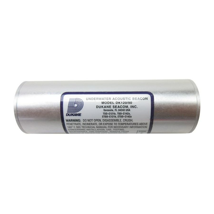
UNDERWATER ACOUSTIC BEACON
MODELS DK100/DK120/DK130/DK140
April 13, 2004
REV 13
DUKANE CORPORATION ST. CHARLES, ILLINOIS 60174 PHONE: 630-762-4050 FAX: 630-762-4049
DOCUMENT NO. 03-TM-0037 © DUKANE CORPORATION
E-MAIL: seacom@dukcorp.com INTERNET: www.dukcorp.com/seacom
Page 1 of 24
03-TM-0037 REV 13
Advertisement
Table of Contents

Summary of Contents for Dukane DK100
- Page 1 SEACOM DIVISION TECHNICAL MANUAL UNDERWATER ACOUSTIC BEACON MODELS DK100/DK120/DK130/DK140 April 13, 2004 REV 13 DUKANE CORPORATION ST. CHARLES, ILLINOIS 60174 PHONE: 630-762-4050 FAX: 630-762-4049 DOCUMENT NO. 03-TM-0037 © DUKANE CORPORATION E-MAIL: seacom@dukcorp.com INTERNET: www.dukcorp.com/seacom Page 1 of 24 03-TM-0037 REV 13...
- Page 2 This manual should be read in its entirety prior to any installation, operation, testing or maintenance of the DK100/DK120/DK130/DK140 Underwater Acoustic Beacons. Page 2 of 24 03-TM-0037 REV 13...
-
Page 3: Table Of Contents
2.3. SURVIVABILITY..8 2.4. ENVIRONMENTAL..8 2.5. MAINTENANCE ... 8 2.6. INSTALLATION PROCEDURES FOR THE DK100/DK120 AND THE N30A26 SE- RIES MOUNTING KIT..9 2.7. INSTALLATION PROCEDURES FOR THE DK100/DK120 AND THE N30A21A MOUNTING KIT..10 2.8. - Page 4 8.2. BEACON RETURN - NO DEFECT..23 8.3. BEACON RETURN - OUT OF WARRANTY..23 8.4. BATTERY CHANGE/OVERHAUL FOR THE DK100 & DK130..23 SECTION IX ... 24 PROCEDURE FOR RETURNING DK SERIES BEACON TO FACTORY ... 24 9.1.
-
Page 5: Section I
DK100/DK120/DK130/DK140 Underwater Acoustic Beacon, hereafter referred to as the “DK Series”, manufactured by Dukane Corporation, Seacom Division, 2900 Dukane Drive, St. Charles, Illinois, 60174. See Figures 1 and 2. These bea- cons have been tested to, and meet, or exceed, all requirements of FAA TSO-C121. - Page 6 DK100/DK120 BEACON SPECIFICATIONS Operating Freuency... Operating Depth... Pulse Length... Pulse Repetition Rate... Operating Life... Battery Life In Beacon... Acoustic Output, Initial... Acoustic Output After 30 Days... Operating Temperature Range... Actuation... Radiation Pattern... Size... Weight, Beacon... Weight, N30A26B Mount... Weight, N30A21A Mount...
- Page 7 DK130/DK140 BEACON SPECIFICATIONS Operating Freuency... 37.5 kHz ± 1 kHz Operating Depth... Pulse Length... Pulse Repetition Rate... Operating Life... Battery Life In Beacon... Acoustic Output, Initial... Acoustic Output After 30 Days... Operating Temperature Range... Actuation... Radiation Pattern... Size... Weight, Beacon... Weight, N30A29 Mount...
-
Page 8: Section Ii
2.1. GENERAL. This section describes the installation of the beacon mounting kits and the installation of the DK Series beacons into these mounts. 2.2. INSTALLATION CRITERIA OF THE BEACON. NOTE All installations to Cockpit Voice Record- ers and Flight Data Recorders should be in accordance with the recorder manufacturer’s approved procedures and hardware. -
Page 9: Installation Procedures For The Dk100/Dk120 And The N30A26 Series Mounting Kit
2.6. INSTALLATION PROCEDURES FOR THE DK100/DK120 AND THE N30A26 SERIES MOUNTING KIT. 2.6.1. GENERAL. Model N30A26 Series Mounting Kit (Cradle Type) is an aluminum extrusion with a screw-attached securing plate that provides rugged mounting and protection of the beacon within the aircraft. See Figure 3. The beacon should be mounted horizontally with the switch end forward, if possible. -
Page 10: Installation Procedures For The Dk100/Dk120 And The N30A21A Mounting Kit
20 inch-pounds torque. F. Perform the Operational Test outlined in Section IV. 2.7. INSTALLATION PROCEDURES FOR THE DK100/DK120 AND THE N30A21A MOUNTING KIT. 2.7.1. GENERAL. Space limitations sometimes require the use of the strap-type N30A21A Mounting Kit. Where a choice exists, horizontal mounting with switch forward is best. -
Page 11: Figure 6. N30A21A Mounting Kit And Beacon Overall Dimensions
If vertical mounting is employed, the switch end should be facing downwards to reduce the accumulation of dirt, grease, and water on the switch end. Rotate the beacon in the mount, so that the markings and beacon replacement date label can be read. Figure 6. -
Page 12: Installation Procedures For The Dk130/Dk140 And The N30A29 Series Mounting Kit
2.8. INSTALLATION PROCEDURES FOR THE DK130/DK140 AND THE N30A29 SERIES MOUNTING KIT. 2.8.1. GENERAL. Model N30A29 Series Mounting Kit (Cradle Type) is an aluminum extrusion with a screw-attached securing plate that provides rugged mounting and protection of the beacon within the aircraft. See Figure 9. The beacon should be mounted horizontally with the switch end forward, if possible. -
Page 13: Installation Procedures For The Dk130/Dk140 And The N30A21A Mounting Kit
B. Make sure that the beacon case and water switch, are free of grease or film. If in doubt, wipe clean with mild detergent C. Test the beacon as outlined in Section IV to insure operation prior to installation. Figure 10. Installation of N30A29 Series Mounting Kit and Beacon D. -
Page 14: Figure 12. N30A21A Mounting Kit And Beacon Overall Dimensions
E. Insert the ends of the retainer straps through the 0.272 inch (0.691 cm) holes in the mounting surface. When horizontal mounting is used, position beacon with switch end forward. If vertical mounting is employed, the switch end should be facing downwards to reduce the accumulation of grease and dirt on the switch end. -
Page 15: Section Iii
3.1. THEORY OF OPERATION. 3.1.1. The DK Series beacon is a battery-oper- ated underwater acoustic pulse generator that is activated when the water switch is immersed in either fresh or salt water. 3.1.2. The water switch is part of a triggering circuit, which when actuated will initiate normal pulsing of the beacon circuit. -
Page 16: Testing
The TS100 Portable Test Set is not compatible with the model DK130 or the DK140 Underwa- ter Acoustic Beacons. The TS200 Test Set is compatible with the DK100, DK120, DK130 and the DK140 Underwater Acoustic Beacons. 03-TM-0037 REV 13 VOLTAGE 3.55 VOLTS... -
Page 17: Beacon Cleaning & Testing
5.3.2. See Sections 4.2. and 4.3. for testing procedures. 5.4. PRECAUTIONS. 5.4.1. The DK100/DK130 Beacons must not be exposed to heat in excess of 160°F (71°C). 5.4.2. The beacon must not be disassembled in any way. Any disassembly of the beacon will void the warranty. -
Page 18: Maintenance Dk120/Dk140
MAINTENANCE DK120/DK140 6.1. GENERAL. This section contains DK120/DK140 Beacon cleaning, beacon testing, battery replacement and testing, disposal and storage procedures. Initially beacons must be tested at every installation or battery change. The required schedule for Bat- tery Replacement and Off-Current Testing is every six years. -
Page 19: Figure 18. Battery End Cover Removal With Vise Clamp And Spanner Wrench
O-ring groove and threads. NOTE: O-ring, lubricant and battery are provided in battery replacement kit see Figure 19 for battery kit number. Contact Dukane Corporation, Seacom Division at (630) 762-4050, for replacement battery kits. I. Install new battery. Be sure the end marked “INSERT THIS END FIRST “... -
Page 20: Figure 20. Beacon Exploded View Showing Relative Location Of Battery And Related Parts
Figure 20. Beacon Exploded View Showing Relative Location of Battery WARNING REPLACE BATTERY WITH AUTHO- RIZED REPLACEMENT PARTS ONLY. USE OF AN UNAUTHO- RIZED BATTERY WILL VOID THE WARRANTY AND MAY CAUSE AN INOPERATIVE OR DANGEROUS CONDITION. USE OF AN UNAU- THORIZED BATTERY MAY PRESENT A RISK OF FIRE OR EXPLOSION. -
Page 21: Beacon Off-Current Test
Figure 21. RBB Label Placement 6.7. BEACON OFF-CURRENT TEST. Connect test leads as shown in Figure 22 and check for current leakage between battery and beacon body. The battery OFF current must be less than 3 microamperes. Beacons with greater than 3 microamperes OFF current should be taken out of service immediately. -
Page 22: Section Vii
DK140 Underwater Acoustic Beacon (hereafter referred to as the “unit”) will be free from defects in materials and workmanship for six years from the date of shipment from Dukane Corporation. Dukane Corporation will remanufacture or replace any unit or battery found not to be in conformity with this warranty. -
Page 23: Section Viii
Warranty, the cost Notes: 1. See Section IX for information about how to return the beacon to Dukane Corporation for service. 2. Call Dukane Corporation, Seacom Division at (630) 762-4056 for appropriate service charges or further information about the Service Program. -
Page 24: Procedure For Returning Dk Series Beacon To Factory
C. Return Authorization Number (See 9.1.3.). D. Purchase Order (if required) for Beacon Replacement. 9.1.3. RETURN AUTHORIZATION. Prior to shipping the beacon to Dukane Corporation, a Return Authorization Number may be required and can be obtained from Dukane Corporation, Seacom Division’s Service Department by calling (630)762-4056, or via Fax (630)762- 4049, or via e-mail at seacom@dukcorp.com. - Page 25 Page 25 of 24 03-TM-0037 REV 13...