Asus F1A55-M LX3 PLUS R2.0 User Manual
F1a55-m lx3 r2.0 series
Hide thumbs
Also See for F1A55-M LX3 PLUS R2.0:
- User manual (68 pages) ,
- Quick start manual (14 pages)
Table of Contents
Advertisement
Advertisement
Table of Contents

Related Manuals for Asus F1A55-M LX3 PLUS R2.0


Summary of Contents for Asus F1A55-M LX3 PLUS R2.0
- Page 1 F1A55-M LX3 R2.0 Series • F1A55-M LX3 R2.0 • F1A55-M LX3 PLUS R2.0...
- Page 2 Product warranty or service will not be extended if: (1) the product is repaired, modified or altered, unless such repair, modification of alteration is authorized in writing by ASUS; or (2) the serial number of the product is defaced or missing.
-
Page 3: Table Of Contents
Chapter 1: Product introduction Special features .................... 1-1 1.1.1 Product highlights ................1-1 1.1.2 ASUS Hybrid DIGI+ VRM ............... 1-1 1.1.3 ASUS Exclusive Features ............... 1-2 Before you proceed ..................1-4 Motherboard overview ................. 1-5 1.3.1 Placement direction ................ 1-5 1.3.2... - Page 4 2.1.2 ASUS EZ Flash 2 ................2-2 2.1.3 ASUS CrashFree BIOS 3 utility ............2-3 2.1.4 ASUS BIOS Updater ............... 2-4 BIOS setup program ..................2-6 Main menu ....................2-10 2.3.1 System Language [English] ............2-10 2.3.2 System Date [Day xx/xx/xxxx] ............2-10 2.3.3...
- Page 5 2.7.8 Boot Option Priorities ..............2-24 2.7.9 Boot Override ................2-24 Tools menu ....................2-25 2.8.1 ASUS EZ Flash 2 Utility ..............2-25 2.8.2 ASUS O.C. Profile ................. 2-25 2.8.3 ASUS SPD Information ..............2-25 Exit menu ....................2-26 Appendices Notices ........................
-
Page 6: Safety Information
Safety information Electrical safety • To prevent electrical shock hazard, disconnect the power cable from the electrical outlet before relocating the system. • When adding or removing devices to or from the system, ensure that the power cables for the devices are unplugged before the signal cables are connected. If possible, disconnect all power cables from the existing system before you add a device. -
Page 7: Conventions Used In This Guide
Refer to the following sources for additional information and for product and software updates. ASUS websites The ASUS website provides updated information on ASUS hardware and software products. Refer to the ASUS contact information. Optional documentation Your product package may include optional documentation, such as warranty flyers, that may have been added by your dealer. -
Page 8: F1A55-M Lx3 R2.0 Series Specifications Summary
DDR3 1866 / 1600 / 1333 / 1066 MHz memory modules * The maximum 32GB memory capacity can be supported with 16GB or above DIMMs. ASUS will update the memory QVL once the DIMMs are available in the market. ** Refer to www.asus.com for the latest Memory QVL (Qualified Vendors List). - Page 9 F1A55-M LX3 R2.0 Series specifications summary ASUS unique features AI Suite II Anti-Surge ASUS UEFI BIOS EZ Mode featuring user-friendly graphics interface ASUS Fan Xpert ASUS CrashFree BIOS 3 ASUS EZ Flash 2 Network iControl ASUS MyLogo 2 Hybrid DIGI+ VRM...
-
Page 10: Package Contents
USB78 USB56 32Mb BIOS SPEAKER AAFP ASUS F1A55-M LX3 R2.0 Series motherboard 2 x Serial ATA 3.0 Gb/s cables 1 x I/O Shield User Guide Support DVD • If any of the above items is damaged or missing, contact your retailer. -
Page 11: Chapter 1: Product Introduction
ASUS Hybrid DIGI+ VRM Hybrid DIGI+ VRM: Maximizing System Potential ASUS brings the exclusive Hybrid DIGI+ VRM design to great value motherboards to better serve a wider range of user needs. Based on technology developed for high performance ASUS products, Hybrid DIGI+ VRM on ASUS motherboards with the AMD A55 chipset allows APU voltage and VRM frequency adjustments via smart preset modes and user-defined profiles. -
Page 12: Asus Exclusive Features
ASUS EZ Flash 2 ASUS EZ Flash 2 is a user-friendly utility that allows you to update the BIOS without using a bootable floppy disk or an OS-based utility. ASUS MyLogo2™... - Page 13 The motherboard is European Union´s Energy-related Products (ErP) ready, and ErP requires products to meet certain energy efficiency requirements in regards to energy consumptions. This is in line with ASUS vision of creating environment-friendly and energy- efficient products through product design and innovation to reduce carbon footprint of the product and thus mitigate environmental impacts.
-
Page 14: Before You Proceed
The illustration below shows the location of the onboard LED. SB_PWR F1A55-M LX3 PLUS R2.0 Standby Power Powered Off F1A55-M LX3 PLUS R2.0 Onboard LED Chapter 1: Product introduction... -
Page 15: Motherboard Overview
Place six screws into the holes indicated by circles to secure the motherboard to the chassis. DO NOT overtighten the screws! Doing so can damage the motherboard. Place this side towards the rear of the chassis. F1A55-M LX3 PLUS R2.0 ASUS F1A55-M LX3 R2.0 Series... -
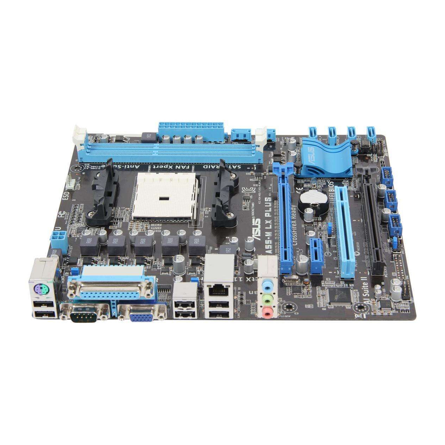
Page 16: Motherboard Layout
1.3.3 Motherboard layout F1A55-M LX3 R2.0 Series motherboards include F1A55-M LX3 PLUS R2.0 and F1A55-M LX3 R2.0 models. The package contents vary from models. The layout illustrations in this user guide are for F1A55-M LX3 PLUS R2.0 only. 18.5cm(7.3in) KBMS... -
Page 17: Layout Contents
Ensure that you use a APU designed for the FM1 socket. The APU fits in only one correct orientation. DO NOT force the APU into the socket to prevent bending the pins and damaging the APU! F1A55-M LX3 PLUS R2.0 F1A55-M LX3 PLUS R2.0 CPU socket FM1 ASUS F1A55-M LX3 R2.0 Series... -
Page 18: Apu Installation
1.4.1 APU installation Chapter 1: Product introduction... -
Page 19: Apu Heatsink And Fan Assembly Installation
1.4.2 APU heatsink and fan assembly installation Apply the Thermal Interface Material to the APU heatsink and APU before you install the heatsink and fan if necessary. To install the APU heatsink and fan assembly ASUS F1A55-M LX3 R2.0 Series... - Page 20 To uninstall the APU heatsink and fan assembly Chapter 1: Product introduction 1-10...
-
Page 21: System Memory
The figure illustrates the location of the DDR3 DIMM sockets: Channel Sockets Channel A DIMM_A1 Channel B DIMM_B1 F1A55-M LX3 PLUS R2.0 F1A55-M LX3 PLUS R2.0 240-pin DDR3 DIMM sockets ASUS F1A55-M LX3 R2.0 Series 1-11... -
Page 22: Memory Configurations
• The maximum 32GB memory capacity can be supported with 16GB or above DIMMs. ASUS will update the memory QVL once the DIMMs are available in the market. • The default memory operation frequency is dependent on its Serial Presence Detect (SPD), which is the standard way of accessing information from a memory module. - Page 23 • 33C9DC GVP34GB13 GEIL 4GB(2 x 2GB) 7-7-7-24 1.5V • • 33C7DC HMT112U6 1.35V Hynix Hynix H5TC1G83TFRH9A • • TFR8A-H9 (low voltage) HMT325U6 Hynix Hynix H5TQ2G83BFRH9C • • BFR8C-H9 (continued on the next page) ASUS F1A55-M LX3 R2.0 Series 1-13...
- Page 24 DDR3-1333MHz capability DIMM socket support Vendors Part No. Size SS/DS Chip Brand Chip No. Timing Voltage (Optional) 1.35V(low Hynix HMT125U6TFR8A-H9 2GB Hynix H5TC1G83TFRH9A • • voltage) HMT351U6BFR8C- Hynix Hynix H5TQ2G83BFRH9C • • FLFD45F-B8KL9 Kingmax Kingmax KKB8FNWBFGNX-27A - • • NAES FLFE85F-C8KF9 Kingmax Kingmax...
- Page 25 6GB(3 x 2GB) DS 1.65V • • KINGSTON KHX1600C9D3T1BK3/ 6GB(3 x 2GB) DS 9-9-9-27 1.65V • • 6GX(XMP) KINGSTON KHX1600C9D3K2/8GX(XMP) 8GB(2 x 4GB) DS 9-9-9-27 1.65V • • Super WA160UX6G9 6GB(3 x 2GB) DS • • Talent ASUS F1A55-M LX3 R2.0 Series 1-15...
- Page 26 A*: Supports one module inserted into either slot as single-channel memory configuration. • B*: Supports two modules inserted into both slots as one pair of dual-channel memory configuration. Visit the ASUS website at www.asus.com for the latest QVL. Chapter 1: Product introduction 1-16...
-
Page 27: Installing A Dimm
1.5.3 Installing a DIMM To remove a DIMM ASUS F1A55-M LX3 R2.0 Series 1-17... -
Page 28: Expansion Slots
Expansion slots In the future, you may need to install expansion cards. The following sub-sections describe the slots and the expansion cards that they support. Unplug the power cord before adding or removing expansion cards. Failure to do so may cause you physical injury and damage motherboard components. -
Page 29: Jumpers
Normal Clear RTC (Default) F1A55-M LX3 PLUS R2.0 Clear RTC RAM Turn OFF the computer and unplug the power cord. Move the jumper cap from pins 1-2 (default) to pins 2-3. Keep the cap on pins 2-3 for about 5~10 seconds, then move the cap back to pins 1-2. -
Page 30: Keyboard Power
+5VSB F1A55-M LX3 PLUS R2.0 (Default) F1A55-M LX3 PLUS R2.0 Keyboard power setting USB device wake-up (3-pin USBPW1-4, 3-pin USBPW5-8) Set these jumpers to +5V to wake up the computer from S1 sleep mode (CPU stopped, DRAM refreshed, system running in low power mode) using the connected USB devices. -
Page 31: Connectors
Mic In Mic In Bass/Center Bass/Center Lime (Front panel) Side Speaker Out To configure an 8-channel audio output: Use a chassis with HD audio module in the front panel to support an 8-channel audio output. ASUS F1A55-M LX3 R2.0 Series 1-21... -
Page 32: Internal Connectors
These are not jumpers! DO NOT place jumper caps on the fan connectors. • The CPU_FAN connector supports a CPU fan of maximum 2A (24 W) fan power. • Only the CPU_FAN connector supports the ASUS Fan Xpert feature. Chapter 1: Product introduction 1-22... -
Page 33: Atx Power Connectors
The system may become unstable or may not boot up if the power is inadequate. • If you are uncertain about the minimum power supply requirement for your system, refer to the Recommended Power Supply Wattage Calculator at http://support.asus. com/PowerSupplyCalculator/PSCalculator.aspx?SLanguage=en-us for details. ASUS F1A55-M LX3 R2.0 Series 1-23... - Page 34 RAID 0, RAID 1, or RAID 10 configuration through the onboard controller. F1A55-M LX3 PLUS R2.0 F1A55-M LX3 PLUS R2.0 SATA 3.0Gb/s connectors • These connectors are set to IDE mode by default. In IDE mode, you can connect Serial ATA boot/data hard disk drives to these connectors.
-
Page 35: System Panel Connector
PIN 1 F1A55-M LX3 PLUS R2.0 +HDLED RESET F1A55-M LX3 PLUS R2.0 System panel connector • System power LED (2-pin PLED) This 2-pin connector is for the system power LED. Connect the chassis power LED cable to this connector. The system power LED lights up when you turn on the system power, and blinks when the system is in sleep mode. - Page 36 F1A55-M LX3 PLUS R2.0 HD-audio-compliant Legacy AC’97 pin definition compliant definition F1A55-M LX3 PLUS R2.0 Front panel audio connector • We recommend that you connect a high-definition front panel audio module to this connector to avail of the motherboard high-definition audio capability. •...
-
Page 37: Usb Connectors
USB56 F1A55-M LX3 PLUS R2.0 PIN 1 PIN 1 F1A55-M LX3 PLUS R2.0 USB2.0 connectors Never connect a 1394 cable to the USB connectors. Doing so will damage the motherboard! The USB 2.0 module is purchased separately. ASUS F1A55-M LX3 R2.0 Series... -
Page 38: Software Support
The contents of the Support DVD are subject to change at any time without notice. Visit the ASUS website at www.asus.com for updates. To run the Support DVD Place the Support DVD into the optical drive. -
Page 39: Chapter 2: Bios Information
BIOS in the future. Copy the original motherboard BIOS using the ASUS Update utility. 2.1.1 ASUS Update utility The ASUS Update is a utility that allows you to manage, save, and update the motherboard BIOS in Windows environment. ®... -
Page 40: Asus Ez Flash 2
Follow the onscreen instructions to complete the updating process. 2.1.2 ASUS EZ Flash 2 The ASUS EZ Flash 2 feature allows you to update the BIOS without using an OS-based utility. Before you start using this utility, download the latest BIOS file from the ASUS website at www.asus.com. -
Page 41: Asus Crashfree Bios 3 Utility
2.1.3 ASUS CrashFree BIOS 3 utility The ASUS CrashFree BIOS 3 is an auto recovery tool that allows you to restore the BIOS file when it fails or gets corrupted during the updating process. You can restore a corrupted BIOS file using the motherboard support DVD or a USB flash drive that contains the updated BIOS file. -
Page 42: Asus Bios Updater
2.1.4 ASUS BIOS Updater The ASUS BIOS Updater allows you to update BIOS in DOS environment. This utility also allows you to copy the current BIOS file that you can use as a backup when the BIOS fails or gets corrupted during the updating process. -
Page 43: Updating The Bios File
At the FreeDOS prompt, type bupdater /pc /g and press <Enter>. D:\>bupdater /pc /g The BIOS Updater screen appears as below. ASUSTek BIOS Updater for DOS V1.30 Current ROM Update ROM BOARD: BOARD: Unknown F1A55-M LX3 PLUS R2.0 VER: 0401 VER: Unknown DATE: 05/02/2012 DATE: Unknown PATH: F1A55MLX3.CAP... -
Page 44: Bios Setup Program
• If the system fails to boot after changing any BIOS setting, try to clear the CMOS and reset the motherboard to the default value. Refer to section 1.7 Jumpers on how to erase the RTC RAM. • The BIOS setup program does not support the bluetooth devices. ASUS F1A55-M LX3 R2.0 Series... -
Page 45: Bios Menu Screen
Advanced Mode EFI BIOS Utility - EZ Mode Exit/Advanced Mode F1A55-M LX3 PLUS R2.0 English BIOS Version : 0401 Build Date : 05/02/2012 CPU Type : AMD Engineering Sample... -
Page 46: Advanced Mode
The Advanced Mode provides advanced options for experienced end-users to configure the BIOS settings. The figure below shows an example of the Advanced Mode. Refer to the following sections for the detailed configurations. To access the EZ Mode, click Exit, then select ASUS EZ Mode. Back button Menu items... -
Page 47: Menu Items
Menu items The highlighted item on the menu bar displays the specific items for that menu. For example, selecting Main shows the Main menu items. The other items (Ai Tweaker, Advanced, Monitor, Boot, Tool, and Exit) on the menu bar have their respective menu items. -
Page 48: Main Menu
RAM to clear the BIOS password. See section 1.7 Jumpers for information on how to erase the RTC RAM. • The Administrator or User Password items on top of the screen show the default Not Installed. After you set a password, these items show Installed. 2-10 ASUS F1A55-M LX3 R2.0 Series... -
Page 49: Administrator Password
Administrator Password If you have set an administrator password, we recommend that you enter the administrator password for accessing the system. Otherwise, you might be able to see or change only selected fields in the BIOS setup program. To set an administrator password: Select the Administrator Password item and press <Enter>. -
Page 50: Ai Tweaker Menu
The configuration options for this section vary depending on the CPU and DIMM model you installed on the motherboard. Scroll down to display the following items: Target CPU Speed : xxxxMHz Displays the current CPU speed. Target DRAM Speed : xxxxMHz Displays the current DRAM speed. 2-12 ASUS F1A55-M LX3 R2.0 Series... -
Page 51: Ai Overclock Tuner [Auto]
2.4.1 Ai Overclock Tuner [Auto] Allows you to select the CPU overclocking options to achieve the desired CPU internal frequency. Select any of these preset overclocking configuration options: [Auto] Loads the optimal settings for the system. [Manual] Allows you to individually set overclocking parameters. [D.O.C.P.] Allows you to select a DRAM O.C. -
Page 52: Dram Timing Control
Allows you to control the power phase based on the CPU’s demands. Configuration options: [Standard] [Optimized] [Extreme] [Manual Adjustment] DO NOT remove the thermal module when switching to Extreme and Manual Adjustment. The thermal conditions should be monitored. 2-14 ASUS F1A55-M LX3 R2.0 Series... -
Page 53: Cpu Voltage [Offset Mode]
2.4.7 CPU Voltage [Offset Mode] [Offset Mode] To offset the voltage by a positive or negative value. CPU Offset Mode Sign [+] To offset the voltage by a positive value. [–] To offset the voltage by a negative value. CPU Offset Voltage [Auto] Allows you to set the CPU Offset voltage. -
Page 54: Advanced Menu
C6 Mode [Auto] Enables or disables C6 mode. Configuration options: [Auto] [Enabled] [Disabled] CPB Mode [Auto] Disables the CPB (Core Performance Boost) mode or set it to [Auto] for automatic configuration. Configuration options: [Disabled] [Auto] 2-16 ASUS F1A55-M LX3 R2.0 Series... -
Page 55: Sata Configuration
AMD PowerNow function [Enabled] Enables or disables the AMD PowerNow function. Configuration options: [Enabled] [Disabled] SVM [Enabled] Enables or disables CPU virtualization. Configuration options: [Disabled] [Enabled] C-state Pmin [Enabled] When this item is set to [Enabled], the system’s processor operates at the lowest power and operating state (C-state). -
Page 56: Usb Configuration
[HD] Sets the front panel audio connector (AAFP) mode to high definition audio. [AC97] Sets the front panel audio connector (AAFP) mode to legacy AC’97. 2-18 ASUS F1A55-M LX3 R2.0 Series... -
Page 57: Apm
Atheros Lan [Enabled] [Enabled] Enables the Atheros LAN controller. [Disabled] Disables the Atheros LAN controller. Atheros Rom [Disabled] This item appears only when you set the previous item to [Enabled] and allows you to enable or disable the Rom Help of the Atheros LAN controller. Configuration options: [Enabled] [Disabled] Serial Port Configuration The sub-items in this menu allow you to set the serial port configuration. -
Page 58: Network Stack
This item allows user to disable or enable the Ipv4 PXE Boot support. Configuration options: [Disable Link] [Enable] Ipv6 PXE Support [Enabled] This item allows user to disable or enable the Ipv6 PXE Boot support. Configuration options: [Disable Link] [Enable] 2-20 ASUS F1A55-M LX3 R2.0 Series... -
Page 59: Monitor Menu
Monitor menu The Monitor menu displays the system temperature/power status, and allows you to change the fan settings. EFI BIOS Utility - Advanced Mode Exit Ai Tweaker Main Advanced Monitor Boot Tool CPU Temperature CPU Temperature +45ºC / +113ºF +45ºC / +113ºF MB Temperature +34ºC / +93ºF CPU Fan Speed... -
Page 60: Cpu Voltage, 3.3V Voltage, 5V Voltage, 12V Voltage
Select Ignore if you do not want to detect this item. 2.6.5 Anti Surge Support [Enabled] This item allows you to enable or disable the Anti Surge function. Configuration options: [Disabled] [Enabled] 2-22 ASUS F1A55-M LX3 R2.0 Series... -
Page 61: Boot Menu
[Disabled] Disables the full screen logo display feature. Set this item to [Enabled] to use the ASUS MyLogo 2™ feature. Post Report [5 sec] This item appears only when the Full Screen Logo item is set to [Disabled] and allows you to set the waiting time for the system to display the post report. -
Page 62: Option Rom Messages [Force Bios]
• To select the boot device during system startup, press <F8> when ASUS Logo appears. • To access Windows OS in Safe Mode, press <F8> after POST. -
Page 63: Tools Menu
> ASUS SPD Information 2.8.1 ASUS EZ Flash 2 Utility Allows you to run ASUS EZ Flash 2. Press [Enter] to launch the ASUS EZ Flash 2 screen. For more details, see section 2.1.2 ASUS EZ Flash 2. 2.8.2 ASUS O.C. Profile This item allows you to store or load multiple BIOS settings. -
Page 64: Exit Menu
This option allows you to enter the EZ Mode screen. Launch EFI Shell from filesystem device This option allows you to attempt to launch the UEFI Shell application (shellx64.efi) from one of the available devices that have a filesystem. 2-26 ASUS F1A55-M LX3 R2.0 Series... -
Page 65: Appendices
Appendices Notices Federal Communications Commission Statement This device complies with Part 15 of the FCC Rules. Operation is subject to the following two conditions: • This device may not cause harmful interference. • This device must accept any interference received including interference that may cause undesired operation. -
Page 66: Canadian Department Of Communications Statement
ASUS Recycling/Takeback Services ASUS recycling and takeback programs come from our commitment to the highest standards for protecting our environment. We believe in providing solutions for you to be able to responsibly recycle our products, batteries, other components as well as the packaging materials. -
Page 67: Asus Contact Information
+1-812-282-3777 +1-510-608-4555 Web site usa.asus.com Technical Support Telephone +1-812-282-2787 Support fax +1-812-284-0883 Online support support.asus.com ASUS COMPUTER GmbH (Germany and Austria) Address Harkort Str. 21-23, D-40880 Ratingen, Germany +49-2102-959911 Web site www.asus.de Online contact www.asus.de/sales Technical Support Telephone +49-1805-010923* Support Fax... - Page 68 Appendices...
- Page 69 F1A55-M LX3 R2.0 Series...