Table of Contents
Advertisement
Quick Links
Advertisement
Table of Contents

Related Manuals for Gigabyte 3D Galaxy II GH-WIU02


Summary of Contents for Gigabyte 3D Galaxy II GH-WIU02
- Page 1 3D Galaxy II GH-WIU02 English User’s Manual...
- Page 2 2. While the water in the tank is lower than the low water-level, the red light on the bottom ™ of PCB will blink. (Please purchase GIGABYTE liquid coolant to fill it.) 3. When the liquid is lower than the low water-level, the system will turn off automatically within four seconds after detection of water inadequacy.
-
Page 3: Table Of Contents
Table content 1 Accessories List 2 Specification Instruction 3 Feature Instruction 4 Liquid Cooling System Installation Installation Preparation ® ® Intel Pentium 4 LAG775 Back Plate Installation PCI Rear Fan Speed Controller Installation Tube Installation 4-way Splitter Valve to the Tube on Waterblock Installation Radiator to 4-way Splitter Valve Installation Radiator to the Inlet of Water Tank 4-way Splitter Valve to the Outlet of Water Pump... -
Page 4: Accessories List
1.Accessories List (1) Radiator (2) Pump + Tank (3) MOSFET Air (4) Waterblock Assembly Cooling Fan X2 pcs X8 pcs (5) 4 - way Splitter (6) 1 / 2 inch Tube (7) Tube Clips (8) Screws Valve ® ® ® ®... - Page 5 Cord X2 pcs X4 pcs (21)Bend Proof Spring (22)Nylon Tie (23)Grease (24)Gigabyte Liquid Coolant (25)Velcro (26)Quick Installtion Guide No.8 Screw: a – Secure PCI Rear Fan Speed Controller ( 1pc ) b – Secure Radiator ( 3pcs ) c – Pump + Tank Assembly ( 2pcs )
-
Page 6: Specification Instruction
2.Specification Instruction Fan size 80 x 80 x 25 mm Fan speed 2000 RPM Mosfet cooling fan Fan Connector 3 pin Bearing Noise 19 dBA Dimensions 61 x 60 x 46 mm Maximum Capacity 400 L/hr Pump Noise 20 dBA Bearing Ceramic Bearing Life time... -
Page 7: Liquid Cooling System Installation
® ® 13.Wide range use for AMD K8/AM2;Intel Pentium 4 LGA 775. ™ <Recommended chassis to use: GIGABYTE 3D Aurora, Triton, Poseidon series Chas- sis> 4.Liquid Cooling System Installation Please follow the instruction. 4-1 Installation Preparation Please make sure the power of PC has been turned off. -
Page 8: Pci Rear Fan Speed Controller Installation
4-3 PCI Rear Fan Speed Controller Installation (as Figure a/b) 4-3-1 Place PCI rear fan speed controller to the back of the chassis (place on the lower PCI is recommended as Figure c.) Figure a Figure b Figure c 4-4 Tube Installation After measuring the distance between each parts of the cooling system, cut the tubes into five suitable sizes as it shows below. -
Page 9: 4-Way Splitter Valve To The Tube On Waterblock Installation
Tube1 Tube3 Tube4 Tube2 Tube5 While placing tube, please do not bend the tube in order to avoid obstructing water flow (as the right Figure under). Besides, if needed, please use bend proof spring on the tube while bending it to avoid obstructing water flow efficiency. 4-5 4-way Splitter Valve to the Tube on Waterblock Installation 4-5-1 Connect one side of tube 1 to... -
Page 10: Radiator To 4-Way Splitter Valve Installation
3 to 4-way splitter valve (1) B and fasten the tube clips (as Figure b). Figure a Figure b Figure c ™ For GIGABYTE 3D Aurora Triton or Poseidon series user, the tube can be threaded through drainage inlet/outlet on the chassis.( as the two holes on the right in Figure c ) -
Page 11: Radiator To The Inlet Of Water Tank
4-6-2 Connect the other side of tube 3 to the inlet of radiator and fasten the tube clips. 4-7 Radiator to the Inlet of Water Tank 4-7-1 Thread Tube 4 through the hole on PCI slot to connect one side of tube 4 to the outlet of radiator and fasten the tube clips. -
Page 12: Waterblock Installation
4-9 Waterblock Installation Please make sure to take off the“CAUTION”sticker and apply the grease on the CPU surface evenly. Note: AMD K8 Bracket can be removed from waterblock (as Figure a) to adjust the appropriate installation direction. (as Figure b/c) Figure a Figure b Figure c... -
Page 13: Amd K8 Clip Installation
® ® 4-10-2 Secure Intel Pentium LGA775 motherboard with attached spring screws. 4-11 AMD K8 Clip Installation 4-11-1 Align the AMD K8 Clip to three 4-11-2 Push down the bar to surely raised points on the CPU. secure. 4-12 AMD AM2 Clip Installation 4-12-1 Align the AMD K8 clip to the 4-12-2... -
Page 14: Fasten 4-Way Splitter Valve
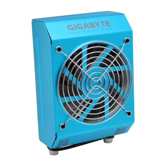
4-13 Fasten 4-way Splitter 4 -14 MOSFET Air Cooling Valve Fan Installation 4-13-1 Using the nylon tie to fasten 4-14-1 Place MOSFET air cooling fan on 4-way splitter valve on trestle of the top of waterblock and make the chassis. If there is no trestle sure that four feet of the air cooling available, try to find an applicable fan are secured on waterblock. -
Page 15: Pump Power Cord Installation
4-15 Pump Power Cord Installation 4-15-1 Prepare Pump Power Cord a : 6-pin connector b : female 2-pin connector c : male 2-pin connector d : 4-pin connector 4-15-2 Connect the Power SW (female 2 - p i n c o n n e c t o r ) f r o m t h e chassis’s panel with the pump power cord male 2-pin connector. -
Page 16: Fan Speed Control Box And Power Cord Instruction
4-16 Fan Speed Control Box and Power Cord Instruction Fan Speed Control Box PCI Rear Fan Speed Control Box Connector Socket Power Cord Fan Speed Control Box Radiator Fan Speed Connect the other side Control Box Connector of power cord with fan 1 Socket to 2 power cord 4-17 Fan Speed Control Box Installation... -
Page 17: Heat Sink Installation
4-17-3 Plug the radiator fan power cord 4-17-4 To accomplish installation, plug the into the fan speed control box. power cord of fan speed control box into the connector on the fan speed control box (as Figure a) and plug the other side of the power cord into the available 1 to 2 socket (as Figure b). -
Page 18: Liquid Cooling System Installation And Test
(as figure showen) Use only GIGABYTE ™ liquid coolant; any damage arising from using other liquid product is not covered by warranty. 5-1 Liquid Cooling System Installation and Test... -
Page 19: Radiator Installation
Be aware of abnormal leakage. If the installation was correct and the tube clips are fastened, and the liquid cooling system leaks, please turn off the ™ power immediately and drain out all coolant. Contact GIGABYTE dealers ™ or GIGABYTE service center. -
Page 20: Liquid Cooling System Disassembly
2 screw holes on the power supply and fasten them up. ™ With GIGABYTE 3D Aurora, Triton, Poseidon series, water tank can be placed inside of the chassis. [use 2 screws (b), please refer to... - Page 21 6-1-3 Release the clip of waterblock 6-1-4 Cut and remove the nylon tie from CPU. which is used to fasten 4-way (Caution: Do not remove the tube splitter valve. at this point) 6-1-5 Remove pump + tank and 4-way 6-1-6 Release the tube clip on the inlet splitter valve from the chassis;...
-
Page 22: 4-Way Splitter Valve Instruction And User Manual
7. 4-way Splitter Valve Instruction and User Manual (Adding VGA waterblock and chipset waterblock without disassembly) Please make sure to ™ Ex. GIGABYTE blue eye and chipset waterblock turn off PC power before installation. Remove the caps and tube clips from 4-way splitter valve. - Page 23 Cut a tube into suitable size; connect one side of the tube with the second splitter on 4-way splitter valve(1) and connect the other side with the outlet of chipset waterblock and fasten the tube clips. Cut a tube into suitable size;...