Advertisement
Quick Links
E-MAXX
+ +
OPERATING INSTRUCTIONS
QUICK SET-UP
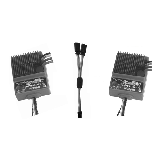
Y-Harness
red
wires
B.
A.
INSTALL SPEED CONTROLS
Use double-sided tape to mount ESCs in the rear tub of
E-Maxx. For more details refer to Step 2.
B.
CONNECT SPEED CONTROLS TO RECEIVER
Plug input signal harnesses of each ESC into the double
side of the Y-Harness. Plug single side of the Y-Harness
into the throttle channel of receiver. If not using stock
E-Maxx receiver, make sure ESC signal harness has
proper wiring sequence.
Refer to Step 1 to change wiring.
C.
CONNECT SPEED CONTROLS TO BATTERIES
Plug the JST/Tamiya connector from the first ESC into
one of the battery packs
(6-7 cell @ 1.2 volts DC/cell)
Plug the second ESC into the other battery pack.
We found that connecting the left side ESC to the right side
motor & battery in the truck keeps excess wire to a minimum,
and you won't have to tie wrap the wires to keep them
inside the truck and away from moving parts.
D.
TURN ON TRANSMITTER POWER
Refer to Step 5 for transmitter adjustments.
E.
TURN ON SPEED CONTROLS
Slide ON/OFF switches to the ON positions.
F.
PRESS AND HOLD ESC 1's ONE-TOUCH BUTTON
With the transmitter throttle in neutral position, press
and hold the One-Touch button on the first speed control
until the status LED turns solid red, then release.
G.
PULL THROTTLE TO FULL-FORWARD POSITION
Hold until status LED turns solid green.
H.
PUSH THROTTLE TO FULL-REVERSE POSITION
Hold until status LED blinks green, then return throttle
to neutral position. LED will then turn solid red indicating
proper programming and throttle is in neutral position.
ROOSTER E-Maxx COMBO
COMBO
Part #1855
The ROOSTERS are the long standing benchmark in reliable
reversible speed controls for 6-7cell/mild-modified set-ups.
With two Roosters installed in your Traxxas E-Maxx using
the included Input Signal Y-Harness, the Rooster E-Maxx
Combo lets you hop-up your E-Maxx with the ability to
run standard 7.2V
motors not recommended)
brakes before the engagement of reverse, and the Roosters
feature Novak's Smart Braking Circuitry
the model to a slow speed before hitting reverse to save
your vehicle's gearbox and reduce speed control heating.
These speed controls feature the original One-Touch Set-Up
(There's nothing easier!)
for the smoothest throttle response and improved radio
system performance, and Reverse Disable Circuitry
that locks-out reverse for racing or forward only use.
Other features include built-in brake light circuitry to
power two high-intensity LEDs for enhanced realism
(available separately in the Novak Brake Light LED Kit
#5655), Radio Priority Circuitry
control even after the battery has discharged, and dual-
level thermal protection.
FOR DETAILED INFO. REFER TO STEPS 1 THRU 6
E-MAXX INSTALLATION PHOTO
CONNECTION PHOTO
6-7 Cell Battery Pack
twist motor
(+)
wires to reduce
C.
RF noise
(-)
brake
light
wires
black
wires
I.
blue
wire
F.
yellow
wire
(+)
C.
6-7 Cell Battery Pack
(-)
trail excess
wire off top of
antenna mast
I.
PRESS AND HOLD ESC 2's ONE-TOUCH BUTTON
With the transmitter throttle in neutral position, press
and hold the One-Touch button on the second ESC
until the status LED turns solid red, then release.
J.
PULL THROTTLE TO FULL-FORWARD POSITION
Hold until status LED turns solid green.
K.
PUSH THROTTLE TO FULL-REVERSE POSITION
Hold until status LED blinks green, then return throttle
to neutral position. LED will then turn solid red indicating
.
proper programming and throttle is in neutral position.
L.
CONNECT SPEED CONTROLS TO THE MOTORS
Use 7.2V (05 or 075 size) standard R/C motors
with 14 turns** or higher in the Traxxas E-Maxx.
Turn off speed controls then transmitter.
Plug the bullet connector on the YELLOW wire of the
first speed control to positive of the first motor.
Plug the bullet connector on the BLUE wire of the first
speed control to negative of the first motor.
Plug the bullet connector on the YELLOW wire of the
second speed control to positive of the second motor.
Plug the bullet connector on the BLUE wire of the second
speed control to negative of the second motor.
Again, we found that connecting the left side ESC to the
right side motor & battery in the truck works best.
M.
KICK-UP A ROOST!
Turn on transmitter and then the speed controls.
**Rooster motor specification is 16 turns or higher (mild modified).
14 turns can be used with E-Maxx using available Traxxas gear ratios.
motors
(05 & 075 size)
(stock Traxxas
. You also get the added benefit of
TM
that brings
, exclusive Polar Drive Technology
TM
to maintain steering
A.
yellow
wire
G/J.
blue
L.
wire
(+)
input
signal
(-)
three 0.1 F
harnass
capacitors
•NO SCHOTTKY•
(+)
L.
(-)
E.
ON/OFF
H/K.
switches
SPECIFICATIONS
Input Voltage
(1.2VDC/cell)
Case Width
Case Depth
Case Height
(w/h.sinks)
Weight
(w/heat sinks)
On-Resist.–Fwd.
(@Trans)
On-Resist.–Rev.
(@Trans)
Rated Current–Fwd.
Rated Current–Rev.
Braking Current
Rev. Delay
(after Smart Braking)
TM
BEC Voltage
BEC Current
TM
Power Wire
Signal Harness
Transistor Type
PWM Frequency
Motor Limit
Part Number
*14 turn motors with available Traxxas E-Maxx gear ratios
PRECAUTIONS
WATER & ELECTRONICS DON'T MIX!
•
operate model in or around water. Never allow water,
moisture, or other foreign materials to get inside the ESC.
• USE NEUTRALLY TIMED MOTORS Using motors with
other than 0 timing will draw excess current in reverse,
and result in ESC overheating and premature motor wear.
Modified motors
(with adjustable end bells)
Johnson/Mabuchi
(closed end bell)
• 6 or 7 CELLS ONLY Never use fewer than 6 or more than
7 cells (7.2-8.4 volts DC) in each main battery pack.
• MOTOR CAPACITORS REQUIRED Three 0.1 F (50V)
ceramic capacitors (included) must be properly installed
on every motor to prevent radio interference.
• ALWAYS USE HEAT SINKS Four heat sinks are factory-
installed on each Rooster, and must be used for maximum
cooling and performance.
• NO REVERSE VOLTAGE! Reverse battery polarity can
damage speed control––Disconnect battery immediately.
• NO SCHOTTKY DIODES External Schottky diodes must
NOT be used with reversible speed controls. Using an
external Schottky diode will damage the ESC.
• DON'T LET TRANSISTOR TABS TOUCH Never allow
separate transistor banks to touch each other or any exposed
metal. This will create a short circuit and damage the ESC.
• DISCONNECT THE BATTERIES Always disconnect the
battery pack from the speed control when not in use.
• TRANSMITTER ON FIRST Turn on your transmitter before
the ESCs so you will have control of the radio equipment.
!
• DON'T GET BURNT
Transistor tabs and the heat sinks
can get extremely hot, so be careful not to touch them
until they cool. Supply adequate air flow for cooling.
• INSULATE WIRES Always insulate exposed wiring with
heat shrink tubing to prevent short circuits.
STEP 1
CHANGING THE INPUT HARNESS
The Rooster speed controls come with the industry standard
input harness connector. This connector works with all
major radio brands. However, with some older style
receivers the sequence of the wires in the plastic connector
housing needs to be changed. This is an important step,
because the electronics inside the receiver may be damaged
if the wiring sequence is incorrect. Changing the wiring is
easily accomplished as described below.
JR • Hitec • New KO • Airtronics Z
If your receiver is a JR, Hitec, Futaba, new KO, or an
Airtronics Z (blue case) you do not need to change the
sequence of the ESC's input harness wires. New KO cases
have tabs on the input harness openings as in Figure 1.
• Insert the input plug into the receiver with the BLACK
wire toward the outside edge of the receiver case.
FIGURE 1
white
tabs
wires
red
wires
black
wires
New KO (with tabs)
Old-style KO • Old-style Sanwa/Airtronics
If your receiver is an older KO or Sanwa/Airtronics, you
must change the sequence of the ESC's input harness
wires. Old Sanwa/Airtronics cases are black in color. Old
KO cases do not have the tab openings (See Figure 2).
• Interchange the red and black wires in the plug plastic
of the ESC's input harness as shown in Figure 3 below.
• Insert the input plug into the receiver with the RED wire
toward the outside edge of the receiver case.
FIGURE 3 With a small standard screwdriver, gently lift
the plastic prong until the wire and metal socket easily
slides out of the plastic housing. Repeat for each wire.
6-7 cells
1.63 inches
2.02 inches
1.22 inches
3.00 ounces
0.018
0.018
100 amps
100 amps
100 amps
Zero Sec.
5.0 volts DC
1.0 amp
16G / 6"
26G / 6"
MEGAFET
1250 Hertz
Mild Modified*
1855
Do not
timed to 0 or
motors are recommended
FIGURE 2
white
no tabs
wires
black
wires
red
wires
Old KO (no tabs)
Advertisement

Related Manuals for NOVAK ROOSTER E-MAXX COMBO


Summary of Contents for NOVAK ROOSTER E-MAXX COMBO
- Page 1 Other features include built-in brake light circuitry to Transistor Type MEGAFET power two high-intensity LEDs for enhanced realism PWM Frequency 1250 Hertz (available separately in the Novak Brake Light LED Kit Motor Limit Mild Modified* #5655), Radio Priority Circuitry to maintain steering Part Number...
- Page 2 Fill out the needed information on • POSITIVE (+) motor tab & GROUND tab*. 10. CONNECT MOTORS this form and return it with the Novak product that re- • NEGATIVE ( ) motor tab & GROUND tab*.