Advertisement
Quick Links
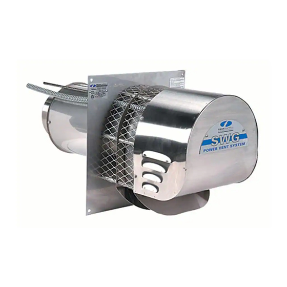
SIDEWALL POWER VENTER KIT
Model: SWG, SWGII & SWG Stainless Series
TYPICAL VENTING SYSTEM COMPONENTS
1 - SWG Series Power Venter
1 - CK Series Control Kit (sold separately)
OPTIONAL SYSTEM COMPONENTS
SWG S
T
ERIES
HROUGH
For installation in wall thickness over 8 inches. Models PEK-4 through PEK-8 are available.
F
M
M
H
OR
OST
ULTIPLE
One CK Series Control Kit for each appliance. Except for a 24V gas furnace or boiler and a
30mV water heater multiple venting system, use the CK-90 Series Control Kit.
CONTENTS
Available Control Kits .................................... 2
Installation Instructions ................................. 2
Wiring............................................................ 7
Air Flow Adjustments .................................... 7
GENERAL SYSTEM INFORMATION
Designed for operation with natural gas, LP gas and #2 fuel oil appliances.
1. The thermostat (wall thermostat or aquastat) calls for heat and energizes a relay which activates
the power venter. After the venter motor has come up to speed, the pressure switch closes. This
closes the circuit to the burner and allows the burner to fire.
2. For millivolt controlled water heaters using the CK-20 Series Control Kit, the gas valve pressure
switch activates the power venter at the same time as the burner fires.
3. After the heating requirement has been satisfied, the thermostat circuit will open and de-activate
the burner and power venter circuit.
4. For venting systems equipped with a post purge device, the power venter operates for a period
of time after the burner has shut off to purge remaining flue gases.
THESE INSTRUCTIONS MUST REMAIN WITH EQUIPMENT
*Patented
CK series control kit
sold separately
-W
E
K
ALL
XTENSION
IT
E
S
EATING
QUIPMENT
YSTEMS
DO NOT DESTROY
Maintenance ............................................. 8
General Inspection ................................... 8
Repair Parts.............................................. 9
System Information ................................ 11
Advertisement

Related Manuals for Field Controls 46139100


Summary of Contents for Field Controls 46139100
-
Page 1: Table Of Contents
SIDEWALL POWER VENTER KIT Model: SWG, SWGII & SWG Stainless Series *Patented CK series control kit sold separately TYPICAL VENTING SYSTEM COMPONENTS 1 - SWG Series Power Venter 1 - CK Series Control Kit (sold separately) OPTIONAL SYSTEM COMPONENTS SWG S ERIES HROUGH XTENSION... -
Page 2: Available Control Kits
For gas appliances, use a Field Controls Type MG-1 Barometric Draft Control. For oil appliances use a Field Controls Type M or RC Barometric Draft Control. Gas-fired draft induced systems should have a single-acting barometric draft control installed. - Page 3 INSTALLATION OF SWG POWER VENTER (See Table 1) Table 1 UNIT SIZING CHART MAXIMUM EQUIVALENT FEET OF VENT PIPE MAX* MAX** AT MAX BTU/HR AT 60% OF MAX VENTING WITH MODEL OIL GPH BTU/HR. INPUT BTU/HR INPUT VENT PIPE SIZE INPUT IMPUT 3”...
- Page 4 ROCEDURE ALCULATING OTAL QUIVALENT ENGTH 1. Calculate the total equivalent feet for each type of fitting used in the venting system from the chart below. 2. Calculate the total amount of feet for the straight lengths of vent pipe. 3. Add the equivalent feet for the fitting with the total amount of feet of straight lengths. This will approximate the total equivalent feet of the vent system.
- Page 5 Diagram A 3. After determining the location of the venting system termination point (see Diagram A), cut a square hole through the wall 1" larger than the outer pipe diameter of the power venter. Mount the power venter through the wall, keeping the outer pipe centered in the hole.
- Page 6 Diagram B ONNECTING OWER ENTER PPLIANCE Venting system should be installed and supported in accordance with the National Flue Gas Code A.N.S.I.Z223.1, or in accordance with any local codes. A vent pipe connector shall be supported for the design and weight of the material employed, to maintain clearances, prevent physical damage and separation of joints.
-
Page 7: Wiring
Figure 6 Figure 7 CLASS B AND CLASS L DOUBLE WALL VENT PIPE INSTALLATION (Follow vent pipe manufacturer's listed or recommended clearances from combustible material) 1. Using a hand crimper or a like device, crimp the inner pipe of the SWG power venter approximately 1" long. (See Figure 7) 2. -
Page 8: Maintenance
GENERAL INSTALLATION INSPECTION Recommended procedures for safety inspection of an appliance in accordance with the National Fuel Gas Code A.N.S.I.Z223.1. The following procedure will help evaluate the venting system. It is intended as a guide to aid in determining that the venting system is properly installed and is in a safe condition for continuous use. This procedure should be recognized as a generalized procedure which cannot anticipate all situations. -
Page 9: Repair Parts
REPLACEMENT PARTS Should the motor or blower wheel need replacing, the following replacement items are available. The Repair Motor Assembly contains the Motor and Blower Wheel factory assemble to a mounting bracket. PART NUMBERS MODEL REPAIR MOTOR ASSEMBLY BLOWER WHEEL SWG-3 46196601 46131800... - Page 10 NSTALLATION 1. Insert the blower wheel through the hole in the front plate of the power venter housing. (See Figure 11) 2. Using two nails or awls, align the two center holes of the motor mount bracket and cover plate. Locate the motor assembly into position by sliding the assembly over the mounting holes in the front plate.
-
Page 11: System Information
INITIAL BURNER AND VENTING SYSTEM OPERATIONAL INFORMATION List the following for each operating appliance on the sidewall venting system, as a guide for tune-up or service information annually. DATE: FOR GAS FIRED EQUIPMENT Heating Appliance BTU/HR Input Gas Valve Operation Pressure Vent System Draft Above Draft Hood or Before Barometric Draft Control Measurement... - Page 12 Page 12 P/N 46139100 Rev J 05/01...