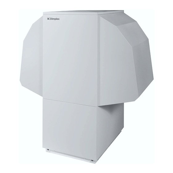
Dimplex LA 17PS Installation And Operating Instructions Manual
Air-to-water heat pump for outdoor installation
Hide thumbs
Also See for LA 17PS:
- Installation and operating instructions manual (48 pages) ,
- Installation and operating instructions manual (52 pages)
Advertisement
Quick Links
LA 17PS
LA 22PS
LA 26PS
Luft/Wasser-
Wärmepumpe für
Außenaufstellung
Bestell-Nr. / Order no. / N
Air-to-Water Heat
Pump for Outdoor
Installation
o
de commande : 452159.66.04
Montage- und
Gebrauchsanweisung
Installation and
Operating Instructions
Instructions d'installation
et d'utilisation
Pompe à chaleur
air-eau pour
installation
extérieure
FD 8703
Advertisement
Chapters

Related Manuals for Dimplex LA 17PS


Summary of Contents for Dimplex LA 17PS
- Page 1 LA 17PS LA 22PS LA 26PS Luft/Wasser- Wärmepumpe für Außenaufstellung Bestell-Nr. / Order no. / N de commande : 452159.66.04 Montage- und Gebrauchsanweisung Installation and Operating Instructions Instructions d’installation et d’utilisation Air-to-Water Heat Pump for Outdoor Installation Pompe à chaleur...
-
Page 2: Table Of Contents
Table of contents Please Read Immediately ...E-2 1.1 Important Information... E-2 1.2 Legal Regulations and Directives ... E-2 1.3 Energy-Efficient Use of the Heat Pump ... E-2 Purpose of the Heat Pump ...E-3 2.1 Application ... E-3 2.2 Operating Principle ... E-3 Scope of Delivery ...E-3... -
Page 3: Please Read Immediately
Please Read Immediately 1.1 Important Information ATTENTION! Any work on the heat pump may only be performed by authorised and qualified after-sales service technicians. ATTENTION! The device is not suitable for operation with a frequency converter. ATTENTION! Never install the device in rooms in which there are any permanent ignition sources. -
Page 4: Purpose Of The Heat Pump
Purpose of the Heat Pump 2.1 Application The air-to-water heat pump is designed for use in existing or newly built heating systems. It is designed exclusively for heating domestic hot water and heating water! The heat pump is suitable for mono energy and bivalent opera- tion down to an external temperature of -20 °C. -
Page 5: Switch Box
Never install the device in rooms in which there are any permanent ignition sources. ATTENTION! When transporting the heat pump, ensure that it is not tilted more than 45° (in any direction). Use a wooden pallet for transporting the heat pump to the final in- stallation location. -
Page 6: Set-Up
The antifreeze function of the heat pump con- troller is active whenever the controller and the heat circulating pump are ready for operation. If the heat pump is taken out of service or in the event of a power failure, the system has to be drained, and if required, blown out, at three locations (see illus- tration). -
Page 7: Electrical Connection
(see Appendix Device Informa- tion) and the applicable VDE (EN) and VNB regulations. The power supply line on the heat pump must be fed through the provided cable feedthrough into the switch box. The line must be firmly screwed to its feedthrough (vapour sealed pipe union). -
Page 8: Maintenance / Cleaning
To prevent acidic cleaning agents from entering the heating sys- tem circuit, we recommend connecting the flushing device di- rectly to the flow and return flow of the liquifier of the heat pump. It is important that the system be thoroughly flushed using appro- priate neutralising agents to prevent any damage from being caused by cleaning agent residue remaining in the system. -
Page 9: Cleaning The Air System
Evaporator, ventilator and condensate outflow should be cleaned of contamination (leaves, twigs, etc.) before each new heating period. Do this by opening the front of the heat pump. The bottom should be opened first followed by the top. ATTENTION! Before opening the device, ensure that all circuits are isolated from the power supply. -
Page 10: Device Information
55 °C heating water flow temperature. 3. Operation with 1 compressors 4. Operation with 2 compressors 5. See CE declaration of conformity 6. The heat circulating pump and the heat pump controller must always be ready for operation. www.dimplex.de LA 17PS IP 24... - Page 11 Anhang / Appendix / Annexes Maßbild / Dimension Drawing / Schéma coté ... A-II 1.1 Maßbild / Dimension Drawing / Schéma coté LA 17PS... A-II 1.2 Maßbild / Dimension Drawing / Schéma coté LA 22PS - LA 26PS ... A-III Diagramme / Diagrams / Diagrammes ...
-
Page 12: Maßbild / Dimension Drawing / Schéma Coté
1 Maßbild / Dimension Drawing / Schéma coté 1.1 Maßbild / Dimension Drawing / Schéma coté LA 17PS A-II... -
Page 13: Maßbild / Dimension Drawing / Schéma Coté La 22Ps - La 26Ps
1.2 Maßbild / Dimension Drawing / Schéma coté LA 22PS - LA 26PS www.dimplex.de A-III... -
Page 14: Diagramme / Diagrams / Diagrammes
2 Diagramme / Diagrams / Diagrammes 2.1 Kennlinien / Characteristic Curves / Courbes caractéristiques LA 17PS A-IV... -
Page 15: Kennlinien / Characteristic Curves / Courbes Caractéristiques La 22Ps
2.2 Kennlinien / Characteristic Curves / Courbes caractéristiques LA 22PS www.dimplex.de... -
Page 16: Kennlinien / Characteristic Curves / Courbes Caractéristiques La 26Ps
2.3 Kennlinien / Characteristic Curves / Courbes caractéristiques LA 26PS A-VI... -
Page 17: Stromlaufpläne / Circuit Diagrams / Schémas Électriques
3 Stromlaufpläne / Circuit Diagrams / Schémas électriques 3.1 Steuerung / Control / Commande www.dimplex.de A-VII... -
Page 18: Last / Load / Charge
3.2 Last / Load / Charge A-VIII... -
Page 19: Anschlussplan / Circuit Diagram / Schéma Électrique
3.3 Anschlussplan / Circuit Diagram / Schéma électrique www.dimplex.de A-IX... -
Page 20: Legende / Legend / Légende
Coding resistor (2k7 / 0.25 W) Flow sensor Defrost end sensor Terminal strip: Incoming supply to the load Terminal strip: Internal wiring Plug connector, control line/heat pump Plug connector, control line / Heat pump controller Solenoid valve, main line (no) Solenoid valve, bypass (nc) Chauffage à... -
Page 21: Hydraulische Prinzipschemen / Hydraulic Plumbing Diagram / Schémas Hydrauliques
4 Hydraulische Prinzipschemen / Hydraulic Plumbing Diagram / Schémas hydrauliques 4.1 Monoenergetische Anlage / Mono Energy System / Installation monoénergétique www.dimplex.de A-XI... -
Page 22: Monoenergetische Anlage Und Warmwasserbereitung / Mono Energy System And Domestic Hot Water Preparation / Installation Monoénergétique Et Production D'eau Chaude
4.2 Monoenergetische Anlage und Warmwasserbereitung / Mono Energy System and Domestic Hot Water Preparation / Installation monoénergétique et production d’eau chaude A-XII... -
Page 23: Bivalente Anlage / Bivalent System / Installation Bivalente
4.3 Bivalente Anlage / Bivalent System / Installation bivalente www.dimplex.de A-XIII... -
Page 24: Legende / Legend / Légende
Shutoff valve with check valve Shutoff valve with drainage Heat consumer Four-way mixer Temperature sensor Flexible connection hose Heat pump Buffer tank Heat pump controller Electrical distribution system Hot water cylinder Boiler Supplementary heating Heat circulating pump Hot water circulating pump Heat pump controller... -
Page 25: Konformitätserklärung / Declaration Of Conformity / Déclaration De Conformité
5 Konformitätserklärung / Declaration of Conformity / Déclaration de conformité www.dimplex.de A-XV... - Page 26 Glen Dimplex Deutschland GmbH Irrtümer und Änderungen vorbehalten. Geschäftsbereich Dimplex Subject to alterations and errors. Am Goldenen Feld 18 Sous réserve d’erreurs et modifications. D-95326 Kulmbach +49 (0) 9221 709 565 www.dimplex.de...