Advertisement
Quick Links
Quick Start Guide
Cisco Small Business
SFE/SGE Managed Switches
Package Contents
SFE/SGE Series Switch
•
•
Power Cord
Mounting Hardware
•
•
Rubber Feet for Desktop Mounting
•
Serial Cable
Quick Start Guide
•
•
SFE/SGE Series CD
1
Before You Begin
This guide is designed to familiarize you with the general layout of the switches,
and how to begin installing them in a standard configuration. Your particular
switch model may not have all of the features or functionality described in this
guide. For more detailed information on the individual switches, see the
SFE/
SGE Managed Switch Administration Guide
.
Before you begin installing the switch, make sure you have all of the package
contents available, access to the
SFE/SGE Managed Switch Administration
Guide
, and a PC with Microsoft Internet Explorer 6.0 or later, for using web-
based system management tools.
N
The switch is configured to operate in a stack by default. If
OTE
you are installing the switch in standalone mode, you must
change the switch configuration. Refer to the stacking
chapter of the
SFE/SGE Managed Switch Administration
Guide
and to Section 3 of this guide.
Switch Location Considerations
The switch can be placed on a desktop or mounted in a rack. If you choose the
desktop option, install the four rubber feet (included) on the bottom of the
switch.
!
C
Wall-mounting the switch is discouraged due to the size
AUTION
and weight of the device.
Rack Mount Installation Tips
Ambient Temperature—To prevent the switch from overheating, do not
•
operate the switch in an area that exceeds an ambient temperature of
104°F (40°C)
Size—The switch can be mounted in any standard size, 19-inch wide rack.
•
Each switch requires 1 rack unit (RU) of space.
•
Reduced Air Flow—If you install the switch in a rack, be sure that there is
adequate air flow as required.
Mechanical Loading—Be sure that the switch is level and stable when you
•
mount the switch in a rack to avoid any hazardous condition.
Circuit Overloading—Do not overload the power outlet or circuit when
•
installing multiple devices in a rack.
•
Reliable Grounding—Be sure that the switch is grounded and uses suitable
electrical supply connections.
To mount the Ethernet switch, follow these instructions:
S
1
Remove the four screws from each side of the front of the switch.
TEP
Retain the screws for re-installation. Do not remove the four screws
from each side of the back of the switch.
S
TEP
2
Place one of the supplied spacers on the side of the switch so the four
holes align to the screw holes. Place a rack mount bracket next to the
spacer and reinstall the four screws removed in step 1.
N
If your screws are not long enough to reattach the bracket with
OTE
the spacer in place, attach the bracket directly to the case
without the spacer.
S
TEP
3
After the mounting hardware has been securely attached, the switch
is now ready to be installed into a standard 19-inch rack as shown.
!
C
AUTION
For stability, load the rack from the bottom to the top, with
the heaviest devices on the bottom. A top-heavy rack is
likely to be unstable and may tip over.
2
Getting to Know the Switch
This guide covers the following products:
•
SFE2000/P
SGE2000/P
•
•
SFE2010/P
•
SGE2010/P
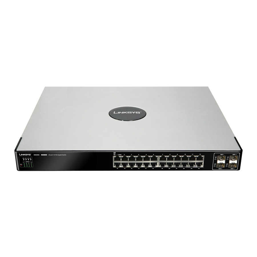
Switch Ports and LEDs
The LEDs and network ports are located on the front panel of the switch. Refer
to the Port Descriptions table, for details on port functionality.
N
OTE
The P in the model name indicates that the switch provides
Power over Ethernet (PoE) to connected devices.
Port Descriptions
Port
Description
Switch Ports
The switch is equipped with auto-sensing, Ethernet (802.3)
network ports which use RJ-45 connectors. The Ethernet
ports support network speeds of 10 Mbps, 100 Mbps, or
1000 Mbps. They can operate in half-duplex and full-duplex
modes. Auto-sensing technology enables each port to
automatically detect the speed and duplex mode of a
connected device, and to adjust both accordingly. These
ports are typically used for devices such as PCs, servers, IP
phones and Access Points.
Uplink Ports
These ports are typically used for connecting to other
switches, routers, or network backbone devices. The mini-
GBIC ports are considered uplink ports.
mini-GBIC
The mini-GBIC (Gigabit Interface Converter) port is a
Ports
connection point for a mini-GBIC expansion module, allowing
the switch to be uplinked via fiber to another switch. Each
mini-GBIC port provides a link to a high-speed network
segment or individual workstation at speeds of up to 1000
Mbps.
Port LEDs
LINK/ACT—Each green LED lights up when a connection is made through its
corresponding port. It flashes when the corresponding port is active.
SPEED—On non-PoE switches, a green LED indicates that the port is operating
at the maximum speed (Fast Ethernet or Gigabit Ethernet).
PoE—On PoE switches, a green LED indicates that PoE is active on that port.
The switch can deliver a maximum of 15.4 Watts to a PoE port. See the
SFE/
SGE Managed Switch Administration Guide
for platform PoE power limitations.
Switch LEDs
PWR—A green LED lights up and remains lit when the switch is powered on.
FAN—A green LED lights up to indicate that the cooling fan is operating
properly. A flashing red LED indicates that the cooling fan has failed.
RPS—A green LED lights up to indicate that RPS is connected and operating
properly. A flashing red LED indicates an RPS fault.
MST—A green LED indicates that this switch is a stack master.
Stack ID—A green LED indicates that this switch is stacked and the
corresponding number indicates its stack ID.
Other Features
Reset—The switch can be reset by inserting a pin or paper clip into the RESET
opening.
RPS—A connector for a Redundant Power Supply is located on the back of the
switch.
Power—The Power port is where you will connect the power cord.
Console—The Console port is where you can connect a serial cable to a PC's
serial port for configuration using a terminal emulation program.
!
C
If the RESET switch is pressed for more than 10 seconds,
AUTION
the switch will reset to its default settings. All customized
user settings will be lost.
Advertisement

Related Manuals for Cisco SGE2000 - Cisco - Gigabit Switch


Summary of Contents for Cisco SGE2000 - Cisco - Gigabit Switch
- Page 1 Circuit Overloading—Do not overload the power outlet or circuit when Port LEDs • Before You Begin Getting to Know the Switch installing multiple devices in a rack. LINK/ACT—Each green LED lights up when a connection is made through its Quick Start Guide corresponding port.
- Page 2 The following table shows the default stacking ports and the configurable 115200 bits per second • Stacking the Switches Connecting Devices Getting Started with the stacking ports: 8 data bits • Configuration • no parity Model Default Stacking Port Configurable Stacking Port •...