
Related Manuals for Dell PowerConnect J-EX4500


Summary of Contents for Dell PowerConnect J-EX4500
- Page 1 Dell PowerConnect J-Series J-EX4500 Ethernet Switch Hardware Guide Published: 2011-05-06 Revision 1...
-
Page 2: Revision
Information in this document is subject to change without notice. All rights reserved. Reproduction of these materials in any manner whatsoever without the written permission of Dell, Inc. is strictly forbidden. Trademarks used in this text: Dell™, the DELL™ logo, and PowerConnect™... - Page 3 1. The Parties. The parties to this Agreement are (i) Juniper Networks, Inc. (if the Customer’s principal office is located in the Americas) or Juniper Networks (Cayman) Limited (if the Customer’s principal office is located outside the Americas) (such applicable entity being referred to herein as “Juniper”), and (ii) the person or organization that originally purchased from Juniper or an authorized Juniper reseller the applicable license(s) for use of the Software (“Customer”) (collectively, the “Parties”).
- Page 4 6. Confidentiality. The Parties agree that aspects of the Software and associated documentation are the confidential property of Juniper. As such, Customer shall exercise all reasonable commercial efforts to maintain the Software and associated documentation in confidence, which at a minimum includes restricting access to the Software to Customer employees and contractors having a need to use the Software for Customer’s internal business purposes.
- Page 5 and such licensor or vendor shall have the right to enforce this Agreement in its own name as if it were Juniper. In addition, certain third party software may be provided with the Software and is subject to the accompanying license(s), if any, of its respective owner(s). To the extent portions of the Software are distributed under and subject to open source licenses obligating Juniper to make the source code for such portions publicly available (such as the GNU General Public License (“GPL”) or the GNU Library General Public License (“LGPL”)), Juniper will make such source code portions (including Juniper modifications, as appropriate) available upon request for a period of up to three...
-
Page 7: Table Of Contents
Chapter 1 Dell PowerConnect J-Series J-EX4500 Switch Overview ....3 J-EX4500 Switches Hardware Overview ....... . . 3 J-EX4500 Switches . - Page 8 Dell PowerConnect J-Series J-EX4500 Ethernet Switch Hardware Guide Network Port and Uplink Module Port Connector Pinout Information for J-EX4500 Switches ............35 Virtual Chassis Ports Connector Pinout Information for J-EX4500 Switches .
- Page 9 Support Service ..........149 Dell Enterprise Training and Certification ....... 149...
- Page 10 Contacting Dell ........
- Page 11 Table of Contents Multiple Power Supplies Disconnection Warning for J-EX Series Switches ..190 TN Power Warning for J-EX Series Switches ......190 Action to Take After an Electrical Accident .
- Page 12 Dell PowerConnect J-Series J-EX4500 Ethernet Switch Hardware Guide...
-
Page 13: About This Guide
This guide, the Dell PowerConnect J-Series J-EX4500 Ethernet Switch Hardware Guide, covers Dell PowerConnect J-Series J-EX4500 Ethernet switches. To download the Dell PowerConnect J-EX Series documentation listed in Table 1 on page xiii, see the following Dell support website: http://www.support.dell.com/manuals... -
Page 14: Downloading Software
Dell PowerConnect J-Series J-EX4500 Ethernet Switch Hardware Guide If the information in the latest release notes differs from the information in the documentation, follow the release notes. Downloading Software You can download Junos OS for J-EX Series switches from the Download Software area . -
Page 15: Repair And Warranty
About This Guide Text and Syntax Conventions Convention Description Examples Plain text like this Represents names of configuration To configure a stub area, include the statements, commands, files, and stub statement at the [edit protocols directories; IP addresses; configuration hierarchy level. ospf area area-id] hierarchy levels;... -
Page 16: Requesting Technical Support
Dell PowerConnect J-Series J-EX4500 Ethernet Switch Hardware Guide Dell is not covered by your warranty. Read and follow the safety instructions that came with the product. For more information, see “Getting Help” on page 147. Requesting Technical Support For technical support, see . -
Page 17: Switch And Components Overview And Specifications
PART 1 Switch and Components Overview and Specifications Dell PowerConnect J-Series J-EX4500 Switch Overview on page 3 Component Descriptions on page 13 Component Specifications on page 33... - Page 18 Dell PowerConnect J-Series J-EX4500 Ethernet Switch Hardware Guide...
-
Page 19: Dell Powerconnect J-Series J-Ex4500 Switch Overview
J-EX Series Ethernet Switches run Junos OS, which provides Layer 2 and Layer 3 switching, routing, and security services. The same Junos OS code base that runs on J-EX Series switches also runs on Dell PowerConnect J-SRX Series Services Gateways. J-EX4500 Switches on page 4... -
Page 20: J-Ex4500 Switches
You can connect two individual J-EX4500 switches together to form one unit and manage the unit as a single chassis, called a Virtual Chassis. You can add up to eight Dell PowerConnect J-EX4200 member switches to form a mixed Virtual Chassis. -
Page 21: Virtual Chassis Module
Chapter 1: Dell PowerConnect J-Series J-EX4500 Switch Overview NOTE: The network ports are located on the front of the switch. To provide carrier-class reliability, J-EX4500 switches include: Dual redundant, load-sharing power supplies that are field-replaceable, hot-removable, and hot-insertable. A field-replaceable fan tray with five fans. The switch remains operational if a single fan fails. -
Page 22: J-Ex4500 Switch Models
Dell PowerConnect J-Series J-EX4500 Ethernet Switch Hardware Guide CAUTION: Mixing power supplies with front-to-back and back-to-front airflow in the same chassis is not supported. Related J-EX4500 Switch Models on page 6 Documentation Field-Replaceable Units in J-EX4500 Switches on page 18 J-EX4500 Switch Models The J-EX4500 switch is available in two models—one with front-to-back airflow and the... -
Page 23: Identifying J-Ex4500 Switch Models
Chapter 1: Dell PowerConnect J-Series J-EX4500 Switch Overview CAUTION: Mixing power supplies with front-to-back airflow and back-to-front airflow in the same chassis is not supported. Related Chassis Physical Specifications for J-EX4500 Switches on page 7 Documentation Front Panel of a J-EX4500 Switch on page 8... -
Page 24: Front Panel Of A J-Ex4500 Switch
Dell PowerConnect J-Series J-EX4500 Ethernet Switch Hardware Guide Table 3: Physical Specifications of the J-EX4500 Switch Chassis Description Value Chassis height 3.5 in. (8.9 cm) Chassis width 17.25 in. (43.82 cm) The outer edges of the front-mounting brackets extend the width to 19 in. (48.3 cm). -
Page 25: Rear Panel Of A J-Ex4500 Switch
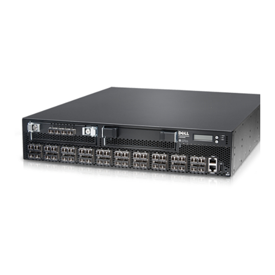
Chapter 1: Dell PowerConnect J-Series J-EX4500 Switch Overview Figure 3: J-EX4500 Switch Front Panel Uplink Menu Chassis modules panel button status LEDs Enter button Console port point MGMT Upper port numbers 0, 2, 4, 6..38 Network ports Management port port 1, 3, 5, 7.. -
Page 26: J-Ex4500 Switch Hardware And Cli Terminology Equivalents
Dell PowerConnect J-Series J-EX4500 Ethernet Switch Hardware Guide Figure 4: J-EX4500 Switch Rear Panel AC appliance AC power Virtual chassis inlets supplies module tray AC power Fan tray handles supply LEDs Related Front Panel of a J-EX4500 Switch on page 8... - Page 27 Chapter 1: Dell PowerConnect J-Series J-EX4500 Switch Overview Table 4: CLI Equivalents of Terms Used in Documentation for J-EX4500 Switches (continued) Hardware Item Item In J-EX4500 (CLI) Description (CLI) Value (CLI) Documentation Additional Information PIC (n) Abbreviated name of n is a value in the...
- Page 28 Dell PowerConnect J-Series J-EX4500 Ethernet Switch Hardware Guide...
-
Page 29: Component Descriptions
LCD panel is configured to display a custom message, the button and the Menu Enter button are disabled. See instructions for configuring the LCD panel on J-EX Series switches in the Dell PowerConnect J-Series Ethernet Switch Complete Software Guide for Junos OS http://www.support.dell.com/manuals... -
Page 30: Lcd Panel Modes
From the J-Web interface, you can view real-time status information in the LCD panel. See the description of the J-Web dashboard for J-EX Series switches in the Dell PowerConnect J-Series Ethernet Switch Complete Software Guide for Junos OS at http://www.support.dell.com/manuals... - Page 31 Menu You can disable the Status menu or the options in the Status menu in the LCD panel. See instructions for configuring the LCD panel in the Dell PowerConnect J-Series Ethernet Switch Complete Software Guide for Junos OS at http://www.support.dell.com/manuals...
- Page 32 SYSTEM HALT option. You can disable the Maintenance menu or the options in the Maintenance menu in the LCD panel. See instructions for configuring the LCD panel in the Dell PowerConnect J-Series Ethernet Switch Complete Software Guide for Junos OS at http://www.support.dell.com/manuals...
-
Page 33: Chassis Status Leds In J-Ex4500 Switches
Chapter 2: Component Descriptions Related Front Panel of a J-EX4500 Switch on page 8 Documentation Field-Replaceable Units in J-EX4500 Switches on page 18 Connecting and Configuring a J-EX Series Switch (CLI Procedure) on page 117 Connecting and Configuring a J-EX Series Switch (J-Web Procedure) on page 118 Chassis Status LEDs in J-EX4500 Switches The front panel of a J-EX4500 switch has three chassis status LEDs (labeled with , and... -
Page 34: Field-Replaceable Units In J-Ex4500 Switches
Front Panel of a J-EX4500 Switch on page 8 Documentation For information about checking active alarms with the J-Web interface and understanding alarm types and severity levels, see the Dell PowerConnect J-Series Ethernet Switch Complete Software Guide for Junos OS at http://www.support.dell.com/manuals Field-Replaceable Units in J-EX4500 Switches Field-replaceable units (FRUs) are components that you can replace at your site. - Page 35 Chapter 2: Component Descriptions Figure 7 on page 19 shows the location of the LEDs on the network ports on the front panel of a J-EX4500 switch. The LEDs point toward the port to which the LEDs belong. Figure 8 on page 19 shows the location of the LEDs on the uplink module ports on the SFP+ uplink module.
-
Page 36: Management Port Leds In J-Ex4500 Switches
Dell PowerConnect J-Series J-EX4500 Ethernet Switch Hardware Guide The Status LED in Figure 7 on page 19 and Figure 8 on page 19 indicate the status of one of the three port parameters. The port parameters are administrative status, duplex mode, and speed. -
Page 37: Ac Power Supply In J-Ex4500 Switches
Chapter 2: Component Descriptions Figure 9: LEDs on the Management Port on a J-EX4500 Switch Management port MGMT MGMT Link/Activity Status Table 9 on page 21 describes the Link/Activity LED. Table 9: Link/Activity LED on the Management Port on a J-EX4500 Switch Color State and Description Link/Activity... - Page 38 Dell PowerConnect J-Series J-EX4500 Ethernet Switch Hardware Guide WARNING: The switch is pluggable type A equipment installed in a restricted-access location. It has a separate protective earthing terminal provided on the chassis in addition to the grounding pin of the power supply cord.
-
Page 39: Ac Power Supply Leds In J-Ex4500 Switches
Chapter 2: Component Descriptions Figure 11: Power Cord Retainer for an AC Power Supply Retainer clip Adjustment Each power supply has its own fan and is cooled by its own internal cooling system. The airflow for a power supply is either from the front of the power supply to the back or from the back of the power supply to the front depending on the switch model you purchase. -
Page 40: Cooling System And Airflow In A J-Ex4500 Switch
Dell PowerConnect J-Series J-EX4500 Ethernet Switch Hardware Guide Figure 12: AC Power Supply LEDs in J-EX4500 Switches AC power supply LEDs Table 11 on page 24 describes the LED on an AC power supply in a J-EX4500 switch. Table 11: Power Supply LED on J-EX4500 Switches... - Page 41 Chapter 2: Component Descriptions Figure 13: Fan Tray Used in a J-EX4500 Switch Fan tray handles The fan tray installs horizontally in the rear of the chassis. The fan tray has two handles, one on each side, that facilitate handling of the fan tray. You remove and replace the fan tray from the rear of the chassis.
- Page 42 Dell PowerConnect J-Series J-EX4500 Ethernet Switch Hardware Guide Figure 15: Front-to-Back Airflow Through the J-EX4500 Switch Chassis (EXHAUST Labels, Arrows Pointing at You) Front Fans (5) Rear In the back-to-front model ( labels and arrows pointing away from you), the air INTAKE intake to cool the chassis is located on the rear of the chassis.
-
Page 43: Uplink Modules In J-Ex4500 Switches
Chapter 2: Component Descriptions CAUTION: To prevent overheating of the chassis, verify that the label and arrow icons on the installed fan tray match the label and arrow icon on the power supply. A match indicates that the direction of airflow through the fan tray matches the direction of airflow of the power supply. - Page 44 Dell PowerConnect J-Series J-EX4500 Ethernet Switch Hardware Guide Figure 17: Uplink Module Slots in a J-EX4500 Switch Uplink Module Uplink Module (PIC 1) (PIC 2) MGMT Each SFP+ uplink module provides four ports. Each module can house four 10-gigabit small form-factor pluggable (SFP+) transceivers or four 1-gigabit small form-factor pluggable (SFP) transceivers.
-
Page 45: Virtual Chassis Module In J-Ex4500 Switches
Optical Interface Support in J-EX4500 Switches on page 40 SFP+ Direct Attach Cables for J-EX Series Switches on page 46 For an overview of J-EX Series Ethernet switch interfaces, see the see the Dell PowerConnect J-Series Ethernet Switch Complete Software Guide for Junos OS at http://www.support.dell.com/manuals... - Page 46 Dell PowerConnect J-Series J-EX4500 Ethernet Switch Hardware Guide Figure 19 on page 30 shows the Virtual Chassis module. Figure 19: Virtual Chassis Module The Virtual Chassis module has two LEDs (labeled ST and VC MODE ) on the left side of its faceplate that indicate the status and the operating mode of the Virtual Chassis module.
- Page 47 Chapter 2: Component Descriptions Field-Replaceable Units in J-EX4500 Switches on page 18 Installing a Virtual Chassis Module in a J-EX4500 Switch on page 93...
- Page 48 Dell PowerConnect J-Series J-EX4500 Ethernet Switch Hardware Guide...
-
Page 49: Component Specifications
Grounding Cable and Lug Specifications for J-EX4500 Switches on page 48 USB Port Specifications for a J-EX Series Switch The following Dell USB flash drives have been tested and are officially supported for the USB port on all J-EX Series switches:... -
Page 50: Console Port Connector Pinout Information For A J-Ex Series Switch
Dell PowerConnect J-Series J-EX4500 Ethernet Switch Hardware Guide For information about booting the switch from a software package stored on a USB flash drive, see the Dell PowerConnect J-Series Ethernet Switch Complete Software Guide for Junos OS at http://www.support.dell.com/manuals Console Port Connector Pinout Information for a J-EX Series Switch The console port on a J-EX Series switch is an RS-232 serial interface that uses an RJ-45 connector to connect to a console management device. -
Page 51: Switches
Chapter 3: Component Specifications The port uses an autosensing RJ-45 connector to support a 10/100/1000Base-T connection. Two LEDs on the port indicate link/activity on the port and the administrative status of the port. See “Management Port LEDs in J-EX4500 Switches” on page 20. Table 15 on page 35 provides the pinout information for the RJ-45 connector for the management port. -
Page 52: Virtual Chassis Ports Connector Pinout Information For J-Ex4500 Switches
Dell PowerConnect J-Series J-EX4500 Ethernet Switch Hardware Guide Table 16: Network Port and Uplink Module Port Connector Pinout Information for J-EX4500 Switches (continued) Signal Description 2-wire serial interface data line SCL- 2-wire serial interface clock MOD_ABS Module absent Rate select 0, optionally controls SFP+ module receiver. - Page 53 Chapter 3: Component Specifications Table 17: Virtual Chassis Ports (VCPs) Connector Pinout Information Pin Number Pin Name P1TXP0 P1TXN0 P1TXP1 P1TXN1 P1TXP2 P1TXN2 P1TXP3 P1TXN3 P2TXP0 P2TXN0...
- Page 54 Dell PowerConnect J-Series J-EX4500 Ethernet Switch Hardware Guide Table 17: Virtual Chassis Ports (VCPs) Connector Pinout Information (continued) Pin Number Pin Name P2TXP1 P2TXN1 P2TXP2 P2TXN2 P2TXP3 P2TXN3 P1RXP0 P1RXN0 P1RXP1 P1RXN1 P1RXP2 P1RXN2 P1RXP3 P1RXN3...
- Page 55 Chapter 3: Component Specifications Table 17: Virtual Chassis Ports (VCPs) Connector Pinout Information (continued) Pin Number Pin Name P2RXP0 P2RXN0 P2RXP1 P2RXN1 P2RXP2 P2RXN2 P2RXP3 P2RXN3 Related Planning J-EX4200 and J-EX4500 Virtual Chassis on page 70 Documentation Understanding J-EX4200 and J-EX4500 Virtual Chassis Components Understanding J-EX4500 Virtual Chassis Hardware Configurations on page 69 Connecting a Virtual Chassis Cable to a J-EX4500 Switch on page 95...
-
Page 56: Optical Interface Support In J-Ex4500 Switches
NOTE: For your J-EX4500 switch, use only the optical transceivers and optical connectors described in this manual. For more information, contact Dell. The Gigabit Ethernet SFP and SFP+ transceivers installed in J-EX4500 switches support digital optical monitoring (DOM): you can view the diagnostic details for these transceivers... - Page 57 Chapter 3: Component Specifications Table 18: Optical Interface Support and Copper Interface Support for Gigabit Ethernet SFP Transceivers in J-EX4500 Switches Ethernet Standard Specifications 1000Base-T Model Number EX-SFP-1GE-T Rate 10/100/1000 Mbps Connector Type RJ-45 Fiber Count Copper Transmitter Wavelength – Minimum Launch Power –...
- Page 58 Dell PowerConnect J-Series J-EX4500 Ethernet Switch Hardware Guide Table 18: Optical Interface Support and Copper Interface Support for Gigabit Ethernet SFP Transceivers in J-EX4500 Switches (continued) Ethernet Standard Specifications 1000Base-LX Model Number EX-SFP-1GE-LX Rate 1000 Mbps Connector Type Fiber Count...
- Page 59 Chapter 3: Component Specifications Table 19: Optical Interface Support for Gigabit Ethernet SFP+ Transceivers in J-EX4500 Switches Ethernet Standard Specifications 10GBase-SR Model Number EX-SFP-10GE-USR Rate 10 Gbps Connector Type Fiber Count Dual Transmitter Wavelength 850 nm Minimum Launch Power –7.3 dBm Maximum Launch Power –1.3 dBm Minimum Receiver Sensitivity...
- Page 60 Dell PowerConnect J-Series J-EX4500 Ethernet Switch Hardware Guide Table 19: Optical Interface Support for Gigabit Ethernet SFP+ Transceivers in J-EX4500 Switches (continued) Ethernet Standard Specifications 10GBase-SR Model Number EX-SFP-10GE-SR Rate 10 Gbps Connector Type Fiber Count Dual Transmitter Wavelength 850 nm Minimum Launch Power –7.3 dBm...
- Page 61 Chapter 3: Component Specifications Table 19: Optical Interface Support for Gigabit Ethernet SFP+ Transceivers in J-EX4500 Switches (continued) Ethernet Standard Specifications 10GBase-LR Model Number EX-SFP-10GE-LR Rate 10 Gbps Connector Type Fiber Count Dual Transmitter Wavelength 1310 nm Minimum Launch Power –8.2 dBm Maximum Launch Power 0.5 dBm...
-
Page 62: Sfp+ Direct Attach Cables For J-Ex Series Switches
Dell PowerConnect J-Series J-EX4500 Ethernet Switch Hardware Guide Table 19: Optical Interface Support for Gigabit Ethernet SFP+ Transceivers in J-EX4500 Switches (continued) Ethernet Standard Specifications 10GBase-ER Model Number EX-SFP-10GE-ER Rate 10 Gbps Connector Type Fiber Count Dual Transmitter Wavelength 1550 nm Minimum Launch Power –4.7 dBm... -
Page 63: Cable Specifications
NOTE: We recommend that you use only SFP+ direct attach cables purchased from Dell with J-EX Series switches. The cables are hot-removable and hot-insertable: You can remove and replace them without powering off the switch or disrupting switch functions. A cable comprises a low-voltage cable assembly that connects directly into two SFP+ ports, one at each end of the cable. -
Page 64: Standards Supported By These Cables
Dell PowerConnect J-Series J-EX4500 Ethernet Switch Hardware Guide Table 20: SFP+ Direct Attach Copper (DAC) Passive Cable Specifications Model Specification Value 1-m DAC SFP+ Cable Rate 10 Gbps full-duplex serial transmission EX-SFP-10GE-DAC-1m Connector type SFP+ passive Twinax cable assembly 3-m DAC SFP+ Cable... - Page 65 Chapter 3: Component Specifications J-EX4500 switch, connect a grounding cable to earth ground and then attach it to the chassis grounding points. CAUTION: For installations that require a separate grounding conductor to the chassis, use the protective earthing terminal on the switch chassis to connect to earth ground.
- Page 66 Dell PowerConnect J-Series J-EX4500 Ethernet Switch Hardware Guide...
-
Page 67: Part 2 Planning For Switch Installation
PART 2 Planning for Switch Installation Site Preparation on page 53 Rack and Cabinet Requirements on page 57 Cable Requirements on page 63 Planning Power Requirements on page 65 Planning the Virtual Chassis on page 69... - Page 68 Dell PowerConnect J-Series J-EX4500 Ethernet Switch Hardware Guide...
-
Page 69: Site Preparation
CHAPTER 4 Site Preparation Site Preparation Checklist for J-EX4500 Switches on page 53 General Site Guidelines on page 54 Site Electrical Wiring Guidelines for J-EX Series Switches on page 55 Environmental Requirements and Specifications for J-EX Series Switches on page 56 Site Preparation Checklist for J-EX4500 Switches The checklist in Table 21 on page 53 summarizes the tasks you need to perform when preparing a site for J-EX4500 switch installation. -
Page 70: General Site Guidelines
Dell PowerConnect J-Series J-EX4500 Ethernet Switch Hardware Guide Table 21: Site Preparation Checklist (continued) Item or Task For More Information Performed By Date Rack or Cabinet Verify that your rack or cabinet meets the “Rack Requirements for J-EX4500 minimum requirements for the installation of Switches”... -
Page 71: Site Electrical Wiring Guidelines For J-Ex Series Switches
Chapter 4: Site Preparation Follow the prescribed ESD prevention procedures to avoid damaging the equipment. Static discharge can cause components to fail completely or intermittently over time. Install the device in a secure area to which only authorized personnel have access. Related Prevention of Electrostatic Discharge Damage on J-EX Series Switches on page 186 Documentation... -
Page 72: Environmental Requirements And Specifications For J-Ex Series Switches
Dell PowerConnect J-Series J-EX4500 Ethernet Switch Hardware Guide Prevention of Electrostatic Discharge Damage on J-EX Series Switches on page 186 AC Power Supply in J-EX4500 Switches on page 21 Environmental Requirements and Specifications for J-EX Series Switches The switch must be installed in a rack or cabinet housed in a dry, clean, well-ventilated, and temperature-controlled environment. -
Page 73: Rack And Cabinet Requirements
CHAPTER 5 Rack and Cabinet Requirements Rack Requirements for J-EX4500 Switches on page 57 Cabinet Requirements for J-EX4500 Switches on page 58 Clearance Requirements for Airflow and Hardware Maintenance for J-EX4500 Switches on page 60 Rack Requirements for J-EX4500 Switches You can mount the switch on two-post racks or four-post racks. -
Page 74: Cabinet Requirements For J-Ex4500 Switches
Dell PowerConnect J-Series J-EX4500 Ethernet Switch Hardware Guide Table 24: Rack Requirements and Specifications for the Switch (continued) Rack Requirement Guidelines Rack size and strength Ensure that the rack complies with the standard for a 19-in. rack as defined in Cabinets, Racks, Panels, and Associated Equipment (document number EIA-310–D) published by the Electronics... -
Page 75: Clearance Requirements For Airflow And Hardware Maintenance For J-Ex4500
Chapter 5: Rack and Cabinet Requirements Table 25: Cabinet Requirements and Specifications for the Switch Cabinet Requirement Guidelines Cabinet size You can mount the switch in a cabinet that contains a 19-in. rack as defined in Cabinets, Racks, Panels, and Associated Equipment (document number EIA-310–D) published by http://www.eia.org the Electronics Industry Association (... -
Page 76: Switches
Dell PowerConnect J-Series J-EX4500 Ethernet Switch Hardware Guide Clearance Requirements for Airflow and Hardware Maintenance for J-EX4500 Switches When planning the site for installing a J-EX4500 switch, you must allow sufficient clearance around the switch. Follow these clearance requirements: Allow at least 6 in. (15.2 cm) of clearance on each side of the chassis. For the cooling system to function properly, the airflow around the chassis must be unrestricted. - Page 77 Chapter 5: Rack and Cabinet Requirements If you are mounting the switch on a rack or cabinet along with other equipment, ensure that the exhaust from other equipment does not blow into the intake vents of the chassis. Leave at least 12 in. (30.5 cm) in front of and 24 in. (61 cm) behind the switch. Allow at least 6 in.
- Page 78 Dell PowerConnect J-Series J-EX4500 Ethernet Switch Hardware Guide...
-
Page 79: Cable Requirements
CHAPTER 6 Cable Requirements Network Cable Specifications for J-EX4500 Switches on page 63 Network Cable Specifications for J-EX4500 Switches J-EX4500 switches have interfaces that use various types of network cables. For instructions on connecting the switch to a network for out-of-band management using an Ethernet cable with an RJ-45 connector, see “Connecting a J-EX Series Switch to a Network for Out-of-Band Management”... - Page 80 Dell PowerConnect J-Series J-EX4500 Ethernet Switch Hardware Guide...
-
Page 81: Planning Power Requirements
CHAPTER 7 Planning Power Requirements AC Power Specifications for J-EX4500 Switches on page 65 AC Power Cord Specifications for a J-EX4500 Switch on page 65 AC Power Specifications for J-EX4500 Switches Table 26 on page 65 lists the AC power specifications for a 1000 W power supply used in J-EX4500 switches. - Page 82 Dell PowerConnect J-Series J-EX4500 Ethernet Switch Hardware Guide Detachable power cords are separately orderable as a field-replaceable unit (FRU) item. Each cord is 2.5 m (approximately 8 ft) long. The coupler type is C19 as described by the International Electrotechnical Commission (IEC) standard 60320. The plug at the male end of the power cord fits into the power source outlet that is standard for your geographical location.
- Page 83 Chapter 7: Planning Power Requirements Table 27: AC Power Cord Specifications for a J-EX4500 Switch (continued) Country/Region Electrical Specification Plug Standard North America 125 VAC, 15 A, 50 Hz NEMA 5–15 125 VAC, 20 A, 50 Hz NEMA 5–20 250 VAC, 16 A, 50 Hz NEMA 6–20 NEMA L6–20 Switzerland...
- Page 84 Dell PowerConnect J-Series J-EX4500 Ethernet Switch Hardware Guide CAUTION: The AC power cord for the J-EX4500 switch is intended for use with this switch only and not for any other use. Power Cable Warning (Japanese) WARNING: The attached power cable is only for this product. Do not use the cable for another product.
-
Page 85: Planning The Virtual Chassis
LCD panel. In a mixed Virtual Chassis, a J-EX4500 switch must be configured in the master and backup roles. For configuration details, see the Dell PowerConnect J-Series Ethernet Switch Complete Software Guide for Junos OS at http://www.support.dell.com/manuals... -
Page 86: Planning J-Ex4200 And J-Ex4500 Virtual Chassis
You can mount the switches in a single rack or install them on multiple racks. For information on the size and strength of J-EX4200 switches and chassis weights and dimensions, see the Dell PowerConnect J-Series J-EX4200 Ethernet Switch Hardware Guide at http://www.support.dell.com/manuals... -
Page 87: Power Requirements For A Virtual Chassis
Plan the installation site to meet the power requirements of the switches in a Virtual Chassis. Related For an overview of J-EX4200 and J-EX4500 Virtual Chassis components, see the Dell Documentation PowerConenct J-Series Ethernet Switch Complete Software Guide for Junos OS at http://www.support.dell.com/manuals... - Page 88 Dell PowerConnect J-Series J-EX4500 Ethernet Switch Hardware Guide...
-
Page 89: Installing And Connecting The Switch And Switch Components
PART 3 Installing and Connecting the Switch and Switch Components Installing the Switch on page 75 Installing Switch Components on page 87 Connecting the Switch on page 99 Performing Initial Configuration on page 111... - Page 90 Dell PowerConnect J-Series J-EX4500 Ethernet Switch Hardware Guide...
-
Page 91: Installing The Switch
CHAPTER 9 Installing the Switch Installing and Connecting a J-EX4500 Switch on page 75 Unpacking a J-EX4500 Switch on page 76 Mounting a J-EX4500 Switch on page 78 Mounting a J-EX4500 Switch on Two Posts in a Rack or Cabinet on page 78 Mounting a J-EX4500 Switch on Four Posts in a Rack or Cabinet on page 81 Mounting a J-EX4500 Switch in a Recessed Position in a Rack or Cabinet on page 85 Installing and Connecting a J-EX4500 Switch... -
Page 92: Unpacking A J-Ex4500 Switch
Dell PowerConnect J-Series J-EX4500 Ethernet Switch Hardware Guide Related Rack Requirements for J-EX4500 Switches on page 57 Documentation Cabinet Requirements for J-EX4500 Switches on page 58 Clearance Requirements for Airflow and Hardware Maintenance for J-EX4500 Switches on page 60 Unpacking a J-EX4500 Switch The J-EX4500 switches are shipped in a cardboard carton, secured with foam packing material. - Page 93 Dell PowerConnect Safety, Environmental, and Regulatory Information End User License Agreement DellPowerConnect Warranty and Support Information Registration and Software Updates for Your Dell PowerConnect J-Series Product Open Source Code Notice Ethernet cable, RJ-45/RJ-45, 4-pair stranded UTP, category #5 RJ-45-to-DB-9 serial port adapter...
-
Page 94: Mounting A J-Ex4500 Switch
Dell PowerConnect J-Series J-EX4500 Ethernet Switch Hardware Guide Mounting a J-EX4500 Switch You can mount a J-EX4500 switch: On two posts in a 19-in. rack or cabinet by using the mounting brackets provided with the switch. On four posts in a 19-in. rack or cabinet by using the separately orderable four-post rack-mount kit. - Page 95 Chapter 9: Installing the Switch Phillips (+) screwdriver, number 2 Flat-blade (-) screwdriver if you are installing the switch in a rack with square, nonthreaded holes 2 mounting brackets and 20 mounting screws (provided in the accessory box shipped with the switch) 8 screws—and 8 cage nuts and washers if your rack requires them—of the appropriate size to secure the chassis to the rack (provided) Dust covers for ports...
- Page 96 Dell PowerConnect J-Series J-EX4500 Ethernet Switch Hardware Guide To ensure that the switch chassis is level after installation, verify that the cage nuts on one side of the rack are aligned with the cage nuts on the other side. Place the switch on a flat, stable surface.
-
Page 97: Mounting A J-Ex4500 Switch On Four Posts In A Rack Or Cabinet
Chapter 9: Installing the Switch Figure 28: Mounting the Switch on Two Posts in a Rack Mounting rack Mounting bracket Have a second person secure the switch to the rack with the appropriate hardware: If you installed cage nuts, install the appropriate screws with washers through the rack holes and into the cage nuts in each post. - Page 98 Dell PowerConnect J-Series J-EX4500 Ethernet Switch Hardware Guide NOTE: If you are mounting the switch on four posts, ensure that the rack is 21.5 in. through 31.5 in. deep if you will mount the switch flush with the rack front and that the rack is 23.5 in. through 32.5 in. deep if you will mount the switch 2 in.
- Page 99 Chapter 9: Installing the Switch Use Figure 29 on page 83 or Figure 30 on page 83 to help you with cage-nut installation. Figure 29: Installing a Round-Hole Cage Nut (Clip Nut) Figure 30: Installing a Square-Hole Cage Nut To ensure that the switch chassis is level after installation, verify that the cage nuts on the front of the rack are aligned with the cage nuts in the back.
- Page 100 Dell PowerConnect J-Series J-EX4500 Ethernet Switch Hardware Guide Figure 31: Attaching the Front Bracket to the Switch Chassis Insert M4x6-mm Phillips flat-head mounting screws into the remaining four holes in the front bracket and tighten the screws. Repeat Steps 2 through 4 for attaching the front bracket to the other side of the chassis.
-
Page 101: Mounting A J-Ex4500 Switch In A Recessed Position In A Rack Or Cabinet
Chapter 9: Installing the Switch Figure 33: Sliding the Rear Brackets to the Rear of a Four-Post Rack Rear bracket Front bracket Attach the rear brackets to the rear post by using the appropriate hardware for your rack. If you installed cage nuts, install the appropriate screws with washers through the rack holes and into the cage nuts in each rear post. - Page 102 Dell PowerConnect J-Series J-EX4500 Ethernet Switch Hardware Guide NOTE: You cannot mount the J-EX4500 switch in a recessed position in a two-post rack or cabinet. Related Connecting Earth Ground to a J-EX Series Switch on page 99 Documentation Rack-Mounting and Cabinet-Mounting Warnings for J-EX Series Switches on page 173...
-
Page 103: Installing Switch Components
CHAPTER 10 Installing Switch Components Installing and Removing J-EX4500 Switch Hardware Components on page 87 Installing a Power Supply in a J-EX4500 Switch on page 88 Installing a Fan Tray in a J-EX4500 Switch on page 89 Installing an Uplink Module in a J-EX4500 Switch on page 91 Installing a Virtual Chassis Module in a J-EX4500 Switch on page 93 Connecting a Virtual Chassis Cable to a J-EX4500 Switch on page 95 Installing a Transceiver in a J-EX Series Switch on page 96... -
Page 104: Installing A Power Supply In A J-Ex4500 Switch
Dell PowerConnect J-Series J-EX4500 Ethernet Switch Hardware Guide Removing a Fan Tray from a J-EX4500 Switch on page 130 “Installing an Uplink Module in a J-EX4500 Switch” on page 91. Removing an Uplink Module from a J-EX4500 Switch on page 131... -
Page 105: Installing A Fan Tray In A J-Ex4500 Switch
Chapter 10: Installing Switch Components To install a power supply in the switch (see Figure 34 on page 89): Ensure that you have the correct power supply: Match the label on the power supply with the label on the fan tray, and verify that both say or both say EXHAUST... - Page 106 Dell PowerConnect J-Series J-EX4500 Ethernet Switch Hardware Guide while the switch is running without turning off power to the switch or disrupting switching functions. The fan tray installs horizontally on the rear of the chassis. Handles on each side of the front faceplate facilitate handling of the fan tray.
-
Page 107: Installing An Uplink Module In A J-Ex4500 Switch
Chapter 10: Installing Switch Components Figure 35: Installing a Fan Tray in a J-EX4500 Switch Fan tray Fan tray handle Related Removing a Fan Tray from a J-EX4500 Switch on page 130 Documentation Cooling System and Airflow in a J-EX4500 Switch on page 24 Field-Replaceable Units in J-EX4500 Switches on page 18 Installing an Uplink Module in a J-EX4500 Switch The uplink module in J-EX4500 switches is a hot-removable and hot-insertable... - Page 108 Dell PowerConnect J-Series J-EX4500 Ethernet Switch Hardware Guide NOTE: When a new uplink module is installed in the switch or an existing uplink module is replaced with another uplink module, the switch detects the newly installed uplink module. The switch creates the required interfaces when new transceivers are installed in those ports.
-
Page 109: Installing A Virtual Chassis Module In A J-Ex4500 Switch
Chapter 10: Installing Switch Components Push both ejector levers towards the uplink module’s faceplate to latch the module in place. Tighten the captive screws in both ejector levers using the Phillips screwdriver, number 2. When the LED turns green, the uplink module is ready for use. Figure 37: Installing an Uplink Module in a J-EX4500 Switch Uplink module Related... - Page 110 Dell PowerConnect J-Series J-EX4500 Ethernet Switch Hardware Guide Phillips (+) screwdriver, number 2 A replacement Virtual Chassis module NOTE: You must remove the fan tray from the J-EX4500 switch before installing the Virtual Chassis module. See “Removing a Fan Tray from a J-EX4500 Switch”...
-
Page 111: Connecting A Virtual Chassis Cable To A J-Ex4500 Switch
Chapter 10: Installing Switch Components Figure 38: Installing the Virtual Chassis Module in a J-EX4500 Switch Related Removing a Virtual Chassis Module from a J-EX4500 Switch on page 133 Documentation Installing and Removing J-EX4500 Switch Hardware Components on page 87 Connecting a Virtual Chassis Cable to a J-EX4500 Switch The Virtual Chassis module has two dedicated Virtual Chassis ports (VCPs) that can be used to interconnect the J-EX4500 switch with J-EX4200 switches or with another... -
Page 112: Installing A Transceiver In A J-Ex Series Switch
NOTE: For your J-EX4500 switch, use only the optical transceivers and optical connectors described in this manual. For more information, contact Dell. Before you begin installing a transceiver in a J-EX Series switch, ensure that you have taken the necessary precautions for safe handling of lasers (see “Laser and LED Safety Guidelines and Warnings for J-EX Series Switches”... - Page 113 Chapter 10: Installing Switch Components To install a transceiver in a J-EX Series switch: CAUTION: To avoid electrostatic discharge (ESD) damage to the transceiver, do not touch the connector pins at the end of the transceiver. Remove the transceiver from its bag. Check to see whether the transceiver is covered by a rubber safety cap.
- Page 114 Dell PowerConnect J-Series J-EX4500 Ethernet Switch Hardware Guide Related Removing a Transceiver from a J-EX Series Switch on page 137 Documentation Connecting a Fiber-Optic Cable to a J-EX Series Switch on page 109 Optical Interface Support in J-EX4500 Switches on page 40...
-
Page 115: Connecting The Switch
CHAPTER 11 Connecting the Switch Connecting Earth Ground to a J-EX Series Switch on page 99 Connecting AC Power to a J-EX4500 Switch on page 101 Connecting a J-EX Series Switch to a Network for Out-of-Band Management on page 103 Connecting a J-EX Series Switch to a Management Console on page 104 Connecting a J-EX Series Switch to a Modem on page 105 Connecting a Fiber-Optic Cable to a J-EX Series Switch on page 109... -
Page 116: Connecting Earth Ground To A J-Ex4500 Switch
Dell PowerConnect J-Series J-EX4500 Ethernet Switch Hardware Guide CAUTION: Using a grounding cable with an incorrectly attached lug can damage the switch. Follow this procedure. Connecting Earth Ground to a J-EX4500 Switch on page 100 Connecting Earth Ground to a J-EX4500 Switch The protective earthing terminal is located on the left rear of the chassis in a J-EX4500 switch. -
Page 117: Connecting Ac Power To A J-Ex4500 Switch
Chapter 11: Connecting the Switch NOTE: If you mounted the switch on four posts of a rack using the four-post rack-mount kit, the protective earthing terminal on the switch is accessible through the slot on the left rear bracket. The protective earthing terminal on the switch mounted on four posts is available only if the rack is 27.5 in. - Page 118 Dell PowerConnect J-Series J-EX4500 Ethernet Switch Hardware Guide NOTE: Each power supply must be connected to a dedicated AC power source outlet. Before you begin to connect power to the switch: Ensure you understand how to prevent ESD damage. See “Prevention of Electrostatic Discharge Damage on J-EX Series Switches”...
-
Page 119: Connecting A J-Ex Series Switch To A Network For Out-Of-Band Management
Chapter 11: Connecting the Switch Insert the coupler end of the jumper cable or power cord into the AC appliance inlet. Push the retainer clip toward the cord until the cord slides into the slot in the adjustment nut. Turn the nut until it is tight against the base of the coupler and the slot in the nut is turned 90°... -
Page 120: Connecting A J-Ex Series Switch To A Management Console
Dell PowerConnect J-Series J-EX4500 Ethernet Switch Hardware Guide Connect the other end of the Ethernet cable to the management device. Figure 45: Connecting a J-EX Series Switch to a Network for Out-of-Band Management Related Connecting a J-EX Series Switch to a Management Console on page 104... -
Page 121: Connecting A J-Ex Series Switch To A Modem
Chapter 11: Connecting the Switch To connect a J-EX Series switch to a management console (see Figure 47 on page 105 and Figure 48 on page 105): Connect one end of the Ethernet cable into the console port (labeled ) on the J-EX Series switch. CONSOLE For the location of the port, see “Front Panel of a J-EX4500 Switch”... -
Page 122: Setting The Serial Console Speed For The Switch
Dell PowerConnect J-Series J-EX4500 Ethernet Switch Hardware Guide An RJ-45-to-DB-9 adapter and an Ethernet cable (provided) A phone cable (not provided) If your computer does not have a DB-9 male connector pin, a USB-to-DB-9 male adapter (not provided) An adapter to connect the RS-232 DB-25 connector on the modem to the... -
Page 123: Configuring The Modem
Chapter 11: Connecting the Switch The boot process proceeds as normal and ends with a login prompt. Configuring the Modem Before you connect the modem, you must configure the modem with required port settings. NOTE: The following procedure uses Hayes-compatible-modem commands to configure the modem. -
Page 124: Connecting The Modem To The Console Port
Dell PowerConnect J-Series J-EX4500 Ethernet Switch Hardware Guide NOTE: You must set the serial port to the fixed speed so that the modem will not adjust the serial port speed to the negotiated line speed. To save the new modem settings, type at the prompt. -
Page 125: Connecting A Fiber-Optic Cable To A J-Ex Series Switch
Chapter 11: Connecting the Switch Turn on the power to your modem. Power on the switch. Related Connecting a J-EX Series Switch to a Management Console on page 104 Documentation Console Port Connector Pinout Information for a J-EX Series Switch on page 34 Connecting a Fiber-Optic Cable to a J-EX Series Switch J-EX Series switches have field-replaceable unit (FRU) optical transceivers to which you can connect fiber-optic cables. - Page 126 Dell PowerConnect J-Series J-EX4500 Ethernet Switch Hardware Guide CAUTION: Do not bend fiber-optic cables beyond their minimum bend radius. An arc smaller than a few inches in diameter can damage the cables and cause problems that are difficult to diagnose.
-
Page 127: Performing Initial Configuration
When you commit changes to the configuration, a new configuration file is created, which becomes the active configuration. You can always revert to the factory default configuration. See the Dell PowerConnect J-Series Ethernet Switch Complete Software Guide for Junos OS at http://www.support.dell.com/manuals... - Page 128 Dell PowerConnect J-Series J-EX4500 Ethernet Switch Hardware Guide commit { factory-settings { reset-chassis-lcd-menu; reset-virtual-chassis-configuration; interfaces { xe-0/0/0 { unit 0 { family ethernet-switching; xe-0/0/1 { unit 0 { family ethernet-switching; xe-0/0/2 { unit 0 { family ethernet-switching; xe-0/0/3 { unit 0 { family ethernet-switching;...
- Page 129 Chapter 12: Performing Initial Configuration unit 0 { family ethernet-switching; xe-0/0/10 { unit 0 { family ethernet-switching; xe-0/0/11 { unit 0 { family ethernet-switching; xe-0/0/12 { unit 0 { family ethernet-switching; xe-0/0/13 { unit 0 { family ethernet-switching; xe-0/0/14 { unit 0 { family ethernet-switching;...
- Page 130 Dell PowerConnect J-Series J-EX4500 Ethernet Switch Hardware Guide family ethernet-switching; xe-0/0/21 { unit 0 { family ethernet-switching; xe-0/0/22 { unit 0 { family ethernet-switching; xe-0/0/23 { unit 0 { family ethernet-switching; xe-0/0/24 { unit 0 { family ethernet-switching; xe-0/0/25 { unit 0 { family ethernet-switching;...
- Page 131 Chapter 12: Performing Initial Configuration xe-0/0/32 { unit 0 { family ethernet-switching; xe-0/0/33 { unit 0 { family ethernet-switching; xe-0/0/34 { unit 0 { family ethernet-switching; xe-0/0/35 { unit 0 { family ethernet-switching; xe-0/0/36 { unit 0 { family ethernet-switching; xe-0/0/37 { unit 0 { family ethernet-switching;...
- Page 132 { storm-control { interface all; Related To revert to the factory default configuration, see the Dell PowerConnect J-Series Documentation Ethernet Switch Complete Software Guide for Junos OS at http://www.support.dell.com/manuals Connecting and Configuring a J-EX Series Switch (CLI Procedure) on page 117...
-
Page 133: Connecting And Configuring A J-Ex Series Switch (Cli Procedure)
If you have configured anything on the switch and want to run EZSetup, revert to the factory default configuration. For instructions, see the Dell PowerConnect J-Series Ethernet Switch Complete Software Guide for Junos OS at http://www.support.dell.com/manuals... -
Page 134: Connecting And Configuring A J-Ex Series Switch (J-Web Procedure)
IP address. If the connection cannot be made, the J-Web interface displays instructions for starting a J-Web session. To configure the switch in a J-EX4500 Virtual Chassis or mixed Virtual Chassis, see the Dell PowerConnect J-Series Ethernet Switch Complete Software Guide for Junos OS at http://www.support.dell.com/manuals Related... - Page 135 Chapter 12: Performing Initial Configuration NOTE: Before you begin the configuration, enable a DHCP client on the management PC you will connect to the switch so that the switch can obtain an IP address dynamically. NOTE: Read the following steps before you begin the configuration. You must complete the initial configuration using EZSetup within 10 minutes.
- Page 136 Dell PowerConnect J-Series J-EX4500 Ethernet Switch Hardware Guide Enter the hostname. This is optional. Enter a password and reenter the password. Specify the time zone. Synchronize the date and time settings of the switch with the management PC or set them manually by selecting the appropriate option button. This is optional.
- Page 137 J-Web interface, but the J-Web interface does not support configuration and management of a J-EX4500 Virtual Chassis. To use the CLI to configure the switch in a J-EX4500 Virtual Chassis or mixed Virtual Chassis, see the Dell PowerConnect J-Series Ethernet Switch Complete Software Guide for Junos OS at http://www.support.dell.com/manuals...
- Page 138 Dell PowerConnect J-Series J-EX4500 Ethernet Switch Hardware Guide...
-
Page 139: Removing The Switch And Switch Components
PART 4 Removing the Switch and Switch Components Removing the Switch on page 125 Removing Switch Components on page 127... - Page 140 Dell PowerConnect J-Series J-EX4500 Ethernet Switch Hardware Guide...
-
Page 141: Removing The Switch
CHAPTER 13 Removing the Switch Removing a J-EX4500 Switch from a Rack or Cabinet on page 125 Removing a J-EX4500 Switch from a Rack or Cabinet If you need to relocate an installed J-EX4500 switch, use the procedure described in this topic. - Page 142 Dell PowerConnect J-Series J-EX4500 Ethernet Switch Hardware Guide If you installed the switch with square-hole cage nuts, a flat-blade (-) screwdriver to remove the cage nuts A labeled bag to hold the removed screws—and the removed cage nuts and washers,...
-
Page 143: Removing Switch Components
CHAPTER 14 Removing Switch Components Installing and Removing J-EX4500 Switch Hardware Components on page 127 Removing a Power Supply from a J-EX4500 Switch on page 128 Removing a Fan Tray from a J-EX4500 Switch on page 130 Removing an Uplink Module from a J-EX4500 Switch on page 131 Removing a Virtual Chassis Module from a J-EX4500 Switch on page 133 Disconnecting a Virtual Chassis Cable from a J-EX4500 Switch on page 135 Disconnecting a Fiber-Optic Cable from a J-EX Series Switch on page 136... -
Page 144: Removing A Power Supply From A J-Ex4500 Switch
Dell PowerConnect J-Series J-EX4500 Ethernet Switch Hardware Guide Installing a Fan Tray in a J-EX4500 Switch on page 89 Removing a Fan Tray from a J-EX4500 Switch on page 130 “Installing an Uplink Module in a J-EX4500 Switch” on page 91. - Page 145 Chapter 14: Removing Switch Components Disconnect power from the switch by performing one of the following tasks: If the AC power source outlet has a power switch, set it to the OFF (0) position. If the AC power source outlet does not have a power switch, gently pull out the male end of the jumper cable or power cord connected to the power source outlet.
-
Page 146: Removing A Fan Tray From A J-Ex4500 Switch
Dell PowerConnect J-Series J-EX4500 Ethernet Switch Hardware Guide Removing a Fan Tray from a J-EX4500 Switch A J-EX4500 switch has a single fan tray. The fan tray is a hot-removable and hot-insertable field-replaceable unit (FRU); you can remove and replace the fan tray while the switch is running without turning off power to the switch or disrupting switching functions. -
Page 147: Removing An Uplink Module From A J-Ex4500 Switch
Chapter 14: Removing Switch Components When the fan stops spinning, slide the fan tray completely out of the chassis. Place the fan tray in the antistatic bag or on the antistatic mat placed on a flat, stable surface. Figure 55: Removing a Fan Tray from a J-EX4500 Switch Fan tray Fan tray handle Squeeze the handles... - Page 148 Dell PowerConnect J-Series J-EX4500 Ethernet Switch Hardware Guide If any transceivers are installed in the uplink module, remove them before you remove the uplink module. For instructions on removing transceivers, see “Removing a Transceiver from a J-EX Series Switch” on page 137.
-
Page 149: Removing A Virtual Chassis Module From A J-Ex4500 Switch
Chapter 14: Removing Switch Components Front Panel of a J-EX4500 Switch on page 8 Removing a Virtual Chassis Module from a J-EX4500 Switch The Virtual Chassis module is installed horizontally on the rear panel of the switch. See “Rear Panel of a J-EX4500 Switch” on page 9. Use the procedure described in this topic to remove the module from the switch chassis. - Page 150 Dell PowerConnect J-Series J-EX4500 Ethernet Switch Hardware Guide Attach the ESD grounding strap to your bare wrist, and connect the strap to the ESD point on the chassis. Remove the fan tray from the switch. See “Removing a Fan Tray from a J-EX4500 Switch”...
-
Page 151: Disconnecting A Virtual Chassis Cable From A J-Ex4500 Switch
Chapter 14: Removing Switch Components Disconnecting a Virtual Chassis Cable from a J-EX4500 Switch The Virtual Chassis module has two dedicated Virtual Chassis ports (VCPs) that can be used to interconnect the J-EX4500 switch with J-EX4200 switches or J-EX4500 switches to form a Virtual Chassis. -
Page 152: Disconnecting A Fiber-Optic Cable From A J-Ex Series Switch
Dell PowerConnect J-Series J-EX4500 Ethernet Switch Hardware Guide Planning J-EX4200 and J-EX4500 Virtual Chassis on page 70 Virtual Chassis Ports Connector Pinout Information for J-EX4500 Switches on page 36 Disconnecting a Fiber-Optic Cable from a J-EX Series Switch J-EX Series switches have field-replaceable unit (FRU) optical transceivers to which you can connect fiber-optic cables. -
Page 153: Removing A Transceiver From A J-Ex Series Switch
Chapter 14: Removing Switch Components Removing a Transceiver from a J-EX Series Switch The transceivers for J-EX Series switches are hot-removable and hot-insertable field-replaceable units (FRUs): You can remove and replace them without powering off the switch or disrupting switch functions. Before you begin removing a transceiver from a J-EX Series switch, ensure that you have taken the necessary precautions for safe handling of lasers (see “Laser and LED Safety Guidelines and Warnings for J-EX Series Switches”... -
Page 154: Removing A Cage Nut From A Rack
Dell PowerConnect J-Series J-EX4500 Ethernet Switch Hardware Guide CAUTION: Before removing the transceiver, make sure you open the ejector lever completely until you hear it click. This prevents damage to the transceiver. Using the needlenose pliers, pull the ejector lever out from the transceiver. - Page 155 Chapter 14: Removing Switch Components Figure 60: Removing a Round-Hole Cage Nut (Clip Nut) To remove a square-hole cage nut from a rack, see Figure 61 on page 139. Figure 61: Removing a Square-Hole Cage Nut...
- Page 156 Dell PowerConnect J-Series J-EX4500 Ethernet Switch Hardware Guide...
-
Page 157: Switch And Component Maintenance
PART 5 Switch and Component Maintenance Routine Maintenance on page 143... - Page 158 Dell PowerConnect J-Series J-EX4500 Ethernet Switch Hardware Guide...
-
Page 159: Routine Maintenance
CHAPTER 15 Routine Maintenance Maintaining Fiber-Optic Cables in J-EX Series Switches on page 143 Maintaining Fiber-Optic Cables in J-EX Series Switches Fiber-optic cables connect to optical transceivers that are installed in J-EX Series switches. To maintain fiber-optic cables: When you unplug a fiber-optic cable from a transceiver, place rubber safety caps over the transceiver and on the end of the cable. - Page 160 Dell PowerConnect J-Series J-EX4500 Ethernet Switch Hardware Guide Optical Interface Support in J-EX4500 Switches on page 40...
-
Page 161: Returning Hardware
PART 6 Returning Hardware Getting Help on page 147... - Page 162 Dell PowerConnect J-Series J-EX4500 Ethernet Switch Hardware Guide...
-
Page 163: Getting Help
Use Dell's extensive suite of online services available at Dell Support http://www.support.dell.com ) for help with installation and troubleshooting procedures. See “Online Services” on page 148 for a more extensive list of Dell Support If the preceding steps have not resolved the problem, see “Contacting Dell” on page 151. NOTE: Call Dell Support from a telephone near or at the computer so that the support staff can assist you with any necessary procedures. -
Page 164: Online Services
Dell PowerConnect J-Series J-EX4500 Ethernet Switch Hardware Guide When prompted by Dell's automated telephone system, enter your Express Service Code to route the call directly to the proper support personnel. For instructions on using the Dell Support, see “Support Service” on page 149. -
Page 165: Automated Order-Status Service
Chapter 16: Getting Help Automated Order-Status Service To check on the status of any Dell products that you have ordered, you can go to http://www.support.dell.com , or you can call the automated order-status service. A recording prompts you for the information needed to locate and report on your order. For the telephone number to call for your region, see “Contacting Dell”... -
Page 166: Before You Call
Remember to fill out the Diagnostics Checklist (see “Diagnostics Checklist” on page 150). If possible, turn on your computer before you call Dell for assistance and call from a telephone at or near the computer. You may be asked to type some commands at the keyboard, relay detailed information during operations, or try other troubleshooting steps possible only at the computer itself. -
Page 167: Contacting Dell
Choose the method of contacting Dell that is convenient for you. Locating the Serial Number on a J-EX4500 Switch or Component Before contacting Dell to request an RMA, you must find the serial number and agency label on the switch or component. -
Page 168: Listing The Switch And Components Details With The Cli
Dell PowerConnect J-Series J-EX4500 Ethernet Switch Hardware Guide Listing the Switch and Components Details with the CLI To list the switch and switch components and their serial numbers, enter the CLI command show chassis hardware The following output lists the switch components and serial numbers for a J-EX4500 switch: user@switch>... -
Page 169: Locating The Serial Number Id Labels On Frus In A J-Ex4500 Switch
Chapter 16: Getting Help Locating the Serial Number ID Labels on FRUs in a J-EX4500 Switch The power supplies, fan tray, and uplink modules installed in J-EX4500 switches are field-replaceable units (FRUs). The Virtual Chassis module is an offline field-replaceable FRU. -
Page 170: Packing A J-Ex4500 Switch Or Component For Shipping
Before you begin packing the switch or component: Ensure that you have retrieved the original shipping carton and packing materials. Contact Dell if you do not have these materials, to learn about approved packing materials. See “Returning Items for Warranty Repair or Credit” on page 149. - Page 171 Chapter 16: Getting Help On the console or other management device connected to the switch, enter the CLI operational mode and issue the following command to shut down the switch software: user@switch>request system halt Wait until a message appears on the console confirming that the operating system has halted.
-
Page 172: Packing J-Ex4500 Switch Components For Shipping
Write the RMA number on the exterior of the box to ensure proper tracking. Related Returning Items for Warranty Repair or Credit on page 149 Documentation Unpacking a J-EX4500 Switch on page 76 Dell Support If you need assistance while troubleshooting a switch, please go to the Dell Support website at http://www.support.dell.com... -
Page 173: Safety Information
PART 7 Safety Information General Safety Information on page 159 Radiation and Laser Warnings on page 165 Installation and Maintenance Safety Information on page 171 Power and Electrical Safety Information on page 185... - Page 174 Dell PowerConnect J-Series J-EX4500 Ethernet Switch Hardware Guide...
-
Page 175: General Safety Information
CHAPTER 17 General Safety Information General Safety Guidelines and Warnings for J-EX Series Switches on page 159 Definitions of Safety Warning Levels for J-EX Series Switches on page 160 Fire Safety Requirements for J-EX Series Switches on page 162 Qualified Personnel Warning for J-EX Series Switches on page 163 Warning Statement for Norway and Sweden for J-EX Series Switches on page 164 General Safety Guidelines and Warnings for J-EX Series Switches The following guidelines help ensure your safety and protect the J-EX Series switch from... -
Page 176: Definitions Of Safety Warning Levels For J-Ex Series Switches
Dell PowerConnect J-Series J-EX4500 Ethernet Switch Hardware Guide Replace fuses only with fuses of the same type and rating. Do not open or remove chassis covers or sheet-metal parts unless instructions are provided in the hardware documentation for this product. Such an action could cause severe electrical shock. - Page 177 Chapter 17: General Safety Information involved with electrical circuitry and be familiar with standard practices for preventing accidents. WARNING: Waarschuwing Dit waarschuwingssymbool betekent gevaar. U verkeert in een situatie die lichamelijk letsel kan veroorzaken. Voordat u aan enige apparatuur gaat werken, dient u zich bewust te zijn van de bij elektrische schakelingen betrokken risico's en dient u op de hoogte te zijn van standaard maatregelen om ongelukken te voorkomen.
-
Page 178: Fire Safety Requirements For J-Ex Series Switches
In addition, you should establish procedures to protect your equipment in the event of a fire emergency. Dell products should be installed in an environment suitable for electronic equipment. We recommend that fire suppression equipment be available in the event of a fire in the vicinity of the equipment and that all local fire, safety, and electrical codes and ordinances be observed when installing and operating your equipment. -
Page 179: Qualified Personnel Warning For J-Ex Series Switches
To keep warranties effective, do not use a dry chemical fire extinguisher to control a fire at or near a Dell switch. If a dry chemical fire extinguisher is used, the unit is no longer eligible for coverage under a service agreement. -
Page 180: Warning Statement For Norway And Sweden For J-Ex Series Switches
Dell PowerConnect J-Series J-EX4500 Ethernet Switch Hardware Guide Warnung Gerät nur von geschultem, qualifiziertem Personal installieren oder auswechseln lassen. Avvertenza Solo personale addestrato e qualificato deve essere autorizzato ad installare o sostituire questo apparecchio. Advarsel Kun kvalifisert personell med riktig opplæring bør montere eller bytte ut dette utstyret. -
Page 181: Radiation And Laser Warnings
CHAPTER 18 Radiation and Laser Warnings Laser and LED Safety Guidelines and Warnings for J-EX Series Switches on page 165 Radiation from Open Port Apertures Warning for J-EX Series Switches on page 168 Laser and LED Safety Guidelines and Warnings for J-EX Series Switches J-EX Series switches are equipped with laser transmitters, which are considered a Class 1 Laser Product by the U.S. -
Page 182: Class 1 Led Product Warning
Dell PowerConnect J-Series J-EX4500 Ethernet Switch Hardware Guide Waarschuwing Klasse-1 laser produkt. Varoitus Luokan 1 lasertuote. Attention Produit laser de classe I. Warnung Laserprodukt der Klasse 1. WARNING: Avvertenza Prodotto laser di Classe 1. Advarsel Laserprodukt av klasse 1. Aviso Produto laser de classe 1. - Page 183 Chapter 18: Radiation and Laser Warnings WARNING: Waarschuwing Niet in de straal staren of hem rechtstreeks bekijken met optische instrumenten. WARNING: Varoitus Älä katso säteeseen äläkä tarkastele sitä suoraan optisen laitteen avulla. WARNING: Attention Ne pas fixer le faisceau des yeux, ni l'observer directement à...
-
Page 184: Radiation From Open Port Apertures Warning For J-Ex Series Switches
Dell PowerConnect J-Series J-EX4500 Ethernet Switch Hardware Guide Radiation from Open Port Apertures Warning for J-EX Series Switches WARNING: Because invisible radiation might be emitted from the aperture of the port when no fiber cable is connected, avoid exposure to radiation and do not stare into open apertures. - Page 185 Chapter 18: Radiation and Laser Warnings WARNING: ¡Atención! Debido a que la apertura del puerto puede emitir radiación invisible cuando no existe un cable de fibra conectado, evite mirar directamente a las aperturas para no exponerse a la radiación. WARNING: Varning! Osynlig strålning kan avges från en portöppning utan ansluten fiberkabel och du bör därför undvika att bli utsatt för strålning genom att inte stirra in i oskyddade öppningar.
- Page 186 Dell PowerConnect J-Series J-EX4500 Ethernet Switch Hardware Guide...
-
Page 187: Installation And Maintenance Safety Information
CHAPTER 19 Installation and Maintenance Safety Information Installation Instructions Warning for J-EX Series Switches on page 171 Chassis Lifting Guidelines for J-EX4500 Switches on page 172 Ramp Warning for J-EX Series Switches on page 172 Rack-Mounting and Cabinet-Mounting Warnings for J-EX Series Switches on page 173 Grounded Equipment Warning for J-EX Series Switches on page 177 Maintenance and Operational Safety Guidelines and Warnings for J-EX Series Switches on page 178... -
Page 188: Chassis Lifting Guidelines For J-Ex4500 Switches
Dell PowerConnect J-Series J-EX4500 Ethernet Switch Hardware Guide Varning! Läs installationsanvisningarna innan du kopplar systemet till dess strömförsörjningsenhet. Related General Safety Guidelines and Warnings for J-EX Series Switches on page 159 Documentation Laser and LED Safety Guidelines and Warnings for J-EX Series Switches on page 165... -
Page 189: Rack-Mounting And Cabinet-Mounting Warnings For J-Ex Series Switches
De onderstaande richtlijnen worden verstrekt om uw veiligheid te verzekeren: De Dell switch moet in een stellage worden geïnstalleerd die aan een bouwsel is verankerd. Dit toestel dient onderaan in het rek gemonteerd te worden als het toestel... - Page 190 Les directives ci-dessous sont destinées à assurer la protection du personnel: Le rack sur lequel est monté le Dell switch doit être fixé à la structure du bâtiment.
- Page 191 Le seguenti direttive vengono fornite per garantire la sicurezza personale: Il Dell switch deve essere installato in un telaio, il quale deve essere fissato alla struttura dell'edificio. Questa unità deve venire montata sul fondo del supporto, se si tratta dell'unica unità...
- Page 192 Para garantizar su seguridad, proceda según las siguientes instrucciones: El Dell switch debe instalarse en un bastidor fijado a la estructura del edificio. Colocar el equipo en la parte inferior del bastidor, cuando sea la única unidad en el mismo.
-
Page 193: Grounded Equipment Warning For J-Ex Series Switches
Chapter 19: Installation and Maintenance Safety Information Om denna enhet installeras på en delvis fylld ställning skall ställningen fyllas nedifrån och upp, med de tyngsta enheterna längst ned på ställningen. Om ställningen är försedd med stabiliseringsdon skall dessa monteras fast innan enheten installeras eller underhålls på... -
Page 194: Switches
Dell PowerConnect J-Series J-EX4500 Ethernet Switch Hardware Guide Connecting Earth Ground to a J-EX Series Switch on page 99 Maintenance and Operational Safety Guidelines and Warnings for J-EX Series Switches While performing the maintenance activities for J-EX Series switches, observe the... -
Page 195: Lightning Activity Warning
Chapter 19: Installation and Maintenance Safety Information angeschlossen werden, und können schwere Verbrennungen verursachen oder an die Anschlußklemmen angeschweißt werden. WARNING: Avvertenza Prima di intervenire su apparecchiature collegate alle linee di alimentazione, togliersi qualsiasi monile (inclusi anelli, collane, braccialetti ed orologi). Gli oggetti metallici si riscaldano quando sono collegati tra punti di alimentazione e massa: possono causare ustioni gravi oppure il metallo può... -
Page 196: Operating Temperature Warning
Dell PowerConnect J-Series J-EX4500 Ethernet Switch Hardware Guide WARNING: Waarschuwing Tijdens onweer dat gepaard gaat met bliksem, dient u niet aan het systeem te werken of kabels aan te sluiten of te ontkoppelen. WARNING: Varoitus Älä työskentele järjestelmän parissa äläkä yhdistä tai irrota kaapeleita ukkosilmalla. - Page 197 WARNING: Attention Pour éviter toute surchauffe des routeurs de la gamme Dell switch, ne l'utilisez pas dans une zone où la température ambiante est supérieure à 45° C. Pour permettre un flot d'air constant, dégagez un espace d'au moins 15,2 cm autour des ouvertures de ventilations.
-
Page 198: Product Disposal Warning
15,2 cm à volta das aberturas de ventilação. WARNING: ¡Atención! Para impedir que un encaminador de la serie Dell switch se recaliente, no lo haga funcionar en un área en la que se supere la temperatura ambiente máxima recomendada de 45°... - Page 199 Chapter 19: Installation and Maintenance Safety Information WARNING: Avvertenza L'eliminazione finale di questo prodotto deve essere eseguita osservando le normative italiane vigenti in materia WARNING: Advarsel Endelig disponering av dette produktet må skje i henhold til nasjonale lover og forskrifter. WARNING: Aviso A descartagem final deste produto deverá...
- Page 200 Dell PowerConnect J-Series J-EX4500 Ethernet Switch Hardware Guide...
-
Page 201: Power And Electrical Safety Information
CHAPTER 20 Power and Electrical Safety Information General Electrical Safety Guidelines and Warnings for J-EX Series Switches on page 185 Prevention of Electrostatic Discharge Damage on J-EX Series Switches on page 186 AC Power Electrical Safety Guidelines for J-EX Series Switches on page 188 AC Power Disconnection Warning for J-EX Series Switches on page 189 Multiple Power Supplies Disconnection Warning for J-EX Series Switches on page 190 TN Power Warning for J-EX Series Switches on page 190... -
Page 202: Prevention Of Electrostatic Discharge Damage On J-Ex Series Switches
Dell PowerConnect J-Series J-EX4500 Ethernet Switch Hardware Guide Evaluated to the TN power system. Canada—Canadian Electrical Code, Part 1, CSA C22.1. Locate the emergency power-off switch for the room in which you are working so that if an electrical accident occurs, you can quickly turn off the power. - Page 203 Chapter 20: Power and Electrical Safety Information Always use an ESD grounding strap when you are handling components that are subject to ESD damage, and make sure that it is in direct contact with your skin. If a grounding strap is not available, hold the component in its antistatic bag (see Figure 66 on page 187) in one hand and touch the exposed, bare metal of the switch with the other hand immediately before inserting the component into the switch.
-
Page 204: Ac Power Electrical Safety Guidelines For J-Ex Series Switches
Dell PowerConnect J-Series J-EX4500 Ethernet Switch Hardware Guide AC Power Electrical Safety Guidelines for J-EX Series Switches CAUTION: For switches with AC power supplies, an external surge protective device (SPD) must be used at the AC power source. The following electrical safety guidelines apply to AC-powered switches: Note the following warnings printed on the chassis: “CAUTION: THIS UNIT HAS MORE THAN ONE POWER SUPPLY CORD. -
Page 205: Ac Power Disconnection Warning For J-Ex Series Switches
Chapter 20: Power and Electrical Safety Information AC Power Disconnection Warning for J-EX Series Switches WARNING: Before working on the switch or near power supplies, unplug all the power cords from an AC switch. Waarschuwing Voordat u aan een frame of in de nabijheid van voedingen werkt, dient u bij wisselstroom toestellen de stekker van het netsnoer uit het stopcontact te halen. -
Page 206: Multiple Power Supplies Disconnection Warning For J-Ex Series Switches
Dell PowerConnect J-Series J-EX4500 Ethernet Switch Hardware Guide Multiple Power Supplies Disconnection Warning for J-EX Series Switches WARNING: For J-EX Series switches that have more than one power supply connection, you must ensure that all power connections are fully disconnected so that power to the switch is completely removed. -
Page 207: Action To Take After An Electrical Accident
Chapter 20: Power and Electrical Safety Information Action to Take After an Electrical Accident If an electrical accident results in an injury, take the following actions in this order: Use caution. Be aware of potentially hazardous conditions that could cause further injury. - Page 208 Dell PowerConnect J-Series J-EX4500 Ethernet Switch Hardware Guide...
-
Page 209: Compliance Information
PART 8 Compliance Information Compliance Information on page 195... - Page 210 Dell PowerConnect J-Series J-EX4500 Ethernet Switch Hardware Guide...
-
Page 211: Compliance Information
CHAPTER 21 Compliance Information Agency Approvals for J-EX Series Switches on page 195 Compliance Statements for EMC Requirements for J-EX Series Switches on page 196 Declarations of Conformity for J-EX4500 Switches on page 198 Compliance Statements for Acoustic Noise for J-EX Series Switches on page 199 Agency Approvals for J-EX Series Switches J-EX Series switches comply with the following standards: Safety... -
Page 212: Compliance Statements For Emc Requirements For J-Ex Series Switches
Dell PowerConnect J-Series J-EX4500 Ethernet Switch Hardware Guide EN 61000-4-2 ESD EN 61000-4-3 Radiated Immunity EN 61000-4-4 EFT EN 61000-4-5 Surge EN 61000-4-6 Low Frequency Common Immunity EN 61000-4-11 Voltage Dips and Sags Related Compliance Statements for EMC Requirements for J-EX Series Switches on page 196... -
Page 213: European Community
Chapter 21: Compliance Information CAUTION: Users should not attempt to make electrical ground connections by themselves, but should contact the appropriate inspection authority or an electrician, as appropriate. Users should ensure for their own protection that the electrical ground connections of the power utility, telephone lines, and internal metallic water pipe system, if present, are connected together. -
Page 214: Declarations Of Conformity For J-Ex4500 Switches
Dell PowerConnect J-Series J-EX4500 Ethernet Switch Hardware Guide If this equipment does cause harmful interference to radio or television reception, which can be determined by turning the equipment off and on, the user is encouraged to try and correct the interference by one or more of the following measures: Reorient or relocate the receiving antenna. -
Page 215: Compliance Statements For Acoustic Noise For J-Ex Series Switches
Chapter 21: Compliance Information Related Agency Approvals for J-EX Series Switches on page 195 Documentation Compliance Statements for EMC Requirements for J-EX Series Switches on page 196 Compliance Statements for Acoustic Noise for J-EX Series Switches on page 199 Compliance Statements for Acoustic Noise for J-EX Series Switches Maschinenlärminformations-Verordnung - 3. - Page 216 Dell PowerConnect J-Series J-EX4500 Ethernet Switch Hardware Guide...
-
Page 217: Index
PART 9 Index Index on page 203... - Page 218 Dell PowerConnect J-Series J-EX4500 Ethernet Switch Hardware Guide...
-
Page 219: Index
83 acoustic noise compliance..........199 removing..............126, 138 agency approvals..............195 Canadian EMC compliance..........196 airflow certification and training, Dell..........149 back-to-front..............26 chassis clearance requirements..........60 component serial number labels......152 cooling system..............24 physical specifications............7 front-to-back..............26 status LEDs................17 maintaining..............56... - Page 220 Dell PowerConnect J-Series J-EX4500 Ethernet Switch Hardware Guide components direct attach copper (DAC) cables for each model..............6 overview................46 installation................87 passive, specifications..........48 list by model...............6 standards supported............48 overview................1 disconnecting packing for shipping............156 fiber-optic cable............136 provided with the switch..........76 power................129 serial number label............152 Virtual Chassis cable...........135...
- Page 221 LEDs connecting................99 AC power supplies............23 ALM ..................17 halting the switch, from the LCD panel......16 chassis status..............17 hardware information, Dell support service....149 Class 1 product warning..........166 hardware overview..............3 front panel................17 height, chassis................7 Link/Activity on management port......21 humidity (relative), acceptable.........56 Link/Activity on network ports........19...
- Page 222 Dell PowerConnect J-Series J-EX4500 Ethernet Switch Hardware Guide SFP+ uplink module ports...........18 ST, uplink module............29 network cable connecting for out-of-band ST, Virtual Chassis module........30 status (speed) on management port.....21 management.............103 connecting to a management console....104 Status on network ports..........20 specifications..............63 Status on uplink module ports.........20...
- Page 223 Index power supplies retainer AC LEDs................23 AC power cord...............102 arrow icon indicator............23 Virtual Chassis cable connector.......70, 95 description.................21 Return Materials Authorization See RMA (Return EXHAUST label...............23 Materials Authorization) return installation...............88 returning hardware INTAKE label..............23 packing components for shipping......156 overview................5 packing the switch for shipping......154 removal................128 parts and tools required..........154 serial number label............153...
- Page 224 Dell PowerConnect J-Series J-EX4500 Ethernet Switch Hardware Guide TN power system............190 support warning symbol............160 customer, getting help..........147 safety standards..............195 technical, requesting............xvi seismic (earthquake), tested level........56 troubleshooting, requesting........156 serial number support service, Dell, contacting........149 chassis components, label........152 symbols key, documentation..........xiv fan tray................153 SYS (system) LED..............17...
- Page 225 LED...............20 fiber-optic transceiver warning.........97 removal................131 general................159 serial number..............154 grounded equipment...........177 status LED.................29 grounding warning............22 URLs, Dell.................148 Japanese power cord warning........68 USB flash drives supported..........33 jewelry removal.............178 USB port specifications............33 laser and LED..............165 levels defined..............160 lightening activity............179 VC Mode LED................30 maintenance and operational.........178...
- Page 226 Dell PowerConnect J-Series J-EX4500 Ethernet Switch Hardware Guide...