Table of Contents

Related Manuals for Audi V6 BITURBO


Summary of Contents for Audi V6 BITURBO
- Page 1 Service. The 2.7-litre V6 Biturbo Design and Function Self-study Programme 198 All rights reserved. Subject to change. AUDI AG Dept.I/GS-5 D-85045 Ingolstadt Fax +49.841/89-6367 740.2810.17.20 Technical status: 01/98 Printed in Germany For internal use only...
- Page 2 The 2.7-litre V6 biturbo ..Turbocharged engines are already something The goal of AUDI’s engineers was to realise a of a tradition at AUDI. The task now facing high “basic torque level“ and a torque AUDI’s engineers was to develop a worthy...
-
Page 3: Table Of Contents
Contents Page Engine ............Technical data, crankshaft, cylinder head, camshaft timing, cooling circuit, engine lubrication, overview of components, air ducting, charging, exhaust system, pneumatically controlled systems, charge pressure control, air divert control in overrun, ACF system, crankcase breather Motronic ME 7.1.......... Subfunctions, system overview Subsystems of the Motronic ..... - Page 4 Engine The 2.7-litre V6 biturbo This engine will also be used in the Audi S4 A tuning protective device prevents and Audi A6. the S4 engine control unit being The engine used in the A6 has a comfort- installed in the A6!
- Page 5 The technical data 200,0 Configuration: • 180,0 V6 engine with 90° V-angle and twin 160,0 turbochargers 140,0 Engine code: • 120,0 S4: AGB A6: AJK 100,0 80,0 • Output: 60,0 S4: 195 kW at 5800 rpm A6: 169 kW at 5800 rpm 40,0 20,0 Torque:...
- Page 6 Engine The crankshaft The crankshaft is identical to that used in the The pistons are forged to enable them to 2.8-litre V6 engine. withstand the high loads to which they are subjected. The crankshaft bearing caps are attached to the central crankcase by 4 bolts. Due to the high combustion pressures, a 2- material bearing shell is installed on the connecting rod side.
- Page 7 Cylinder head The cylinder heads are largely identical to The shape of the inlet duct causes the drawn- those used in the V6 naturally aspirated in air to tumble. engine. Common parts are used for both banks of cylinders. Advantages: The mounting position of the right-hand A good degree of swirl and high ignitability •...
- Page 8 Engine The variable valve timing The camshaft timing has been modified The design and function of the compared to the 2.8-litre V6 engine to meet the variable valve timing are already demands of turbocharging technology. described in Self-study Programmes 182 and 192. Variable valve timing with an adjustment angle of 22°...
- Page 9 Cooling circuit Both exhaust gas turbochargers are water- Located in the cooling circuit is a electrical cooled and integrated in the cooling circuit. coolant pump. This pump is required as a means of When the coolant thermostat is closed, the protection against overheating of the coolant coolant flows back to the coolant pump along under high thermal load, e.g.
- Page 10 Engine Electrical coolant circulation pump V51 Due to this reversal of the direction of coolant Electrical coolant circulation pump V51 is flow, coolant is drawn in via the cylinder heads located in the engine’s V angle. (large cross-sections), which means that any vapour bubbles which develop are expelled If the coolant temperature is too high, from the exhaust gas turbocharger lines.
- Page 11 Fan control The control unit for radiator fan V293 regulates the output of the radiator fan and controls the continued coolant circulation. The induced-air fan V7 and the forced-air fan V177 are activated simultaneously. Forced-air fan V177 is located upstream of the condenser, water cooler and visco fan.
- Page 12 Engine Electric circuit of fan control: V293 Air-conditioning pressure switch F129 F129 V177 only for vehicles with air conditioner SSP 198/17 for vehicles with air-conditioning system: Components: Integrated in the pressure switch for air F18/F54 Radiator fan thermoswitch Thermoswitch for continued coolant conditioner F129 is the high-pressure switch function for activating a higher fan setting.
- Page 13 Function of fan circuit (for vehicles with air-conditioning system) 4 fan settings are possible: is activated by coolant pump thermoswitch F95. The electrical coolant function..The fan motors and continued coolant circulation pump V51 are activated. The fan motors run at min. output (40%). The continued coolant function is only activated if the “engine not running“...
- Page 14 A new feature of the biturbo is Bearing cap the “integrated oil supply“ (see The oil circuit of the 2.7-litre V6 biturbo engine largely corresponds to that next page). A duocentric oil pump draws in the oil of the 3rd V6 engine generation.
- Page 15 Engine The component parts of the oil circuit Oil pressure limiting valve The oil pump ..Oil pressure control valve is an internal gear pump. It is attached to the crankcase as a separate component. The oil pump is designed in such a way that it projects deep down into the oil sump and is immersed completely in the engine oil when the oil level is correct.
- Page 16 The oil pressure control valve ..The oil retention valves ..regulates the engine oil pressure. It is prevent the oil running out of the oil filter and integrated in the oil pump housing. The oil the cylinder heads and back into the oil sump quantity “regulated“...
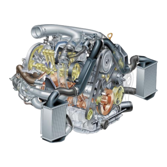
- Page 17 Engine Front view of engine Intake-air temperature sender G42 Hall sender G163 Knock sensor G61 Knock sensor G66 Camshaft adjustment valve N208 Charge air cooler Charge air cooler SSP 198/51 Power assisted steering Oil pressure pump drive switch Visco fan Oil filter Alternator Air-cond.
- Page 18 Rear view of engine Pressure limiting valve Coolant temperature sender F18/F54 Hall sender G40 Camshaft adjustment Distributor piece valve N205 Exhaust gas temperature sender G235 (with evaluation electronics) Thermoswitch for continued cooling function F95 SSP 198/52 Lambda probe G108 Prim. catal. converter Prim.
- Page 19 Engine Top view of engine Solenoid valve for charge Solenoid valve for pressure control N75 activated charcoal Divert air valve for Camshaft turbocharger N249 adjustment valve N205 Fuel pressure regulator Injector Injector SSP 198/54 Divert air valve Divert air valve Hall sender G163 Camshaft adjustment Charge pressure...
- Page 20 View of engine from left Injector Pressure control valve Individual ignition coil Prim. catal. converter SSP 198/53 Exh. gas turbocharger Oil cooler Charge air cooler Pressure unit for wastegate flap Oil filter...
- Page 21 Engine Air ducting Fresh air is induced by the combined air filter Cooling air intakes in the bumper and air vents and air mass meter and distributed to the two in the wheel housing liners ensure that a exhaust gas turbochargers by the air sufficient amount of air flows through the distributor.
- Page 22 Charging Two water-cooled exhaust gas turbochargers Since the turbochargers are flanged • directly onto the exhaust manifold, the with wastegate are used for charging. exhaust gases travel less distance and The charge pressure of both exhaust gas there is less temperature loss. turbochargers is controlled via the common charge pressure control valve N75.
- Page 23 Engine Exhaust system The exhaust manifolds are designed as pipe A new generation of probes is used elbows with insulated air gaps. in this engine. The “planar lambda probe“ is an Advantage: improvement on the finger-type lambda probe (refer to chapter on Less heat loss of the exhaust gas and less •...
- Page 24 Pneumatically controlled systems In the Biturbo, 4 systems are pneumatically ACF system • controlled: The Motronic ME 7.1 activates the solenoid valve for the activated charcoal canister and regulates the fuel vapour feed rate to Charge pressure control • the engine via the vacuum. The Motronic ME 7.1 activates the solenoid valve for charge pressure control N75 and Crankcase breather...
- Page 25 Engine Charge pressure control The air mass required to develop a specific If a defect occurs in one of the cylinder banks level of torque is determined by means of an air (e.g. melting of the catalytic converter or mass calculation and produced by controlling blockage of the exhaust system), a purely air the charge pressure as required.
- Page 26 The solenoid valve for charge pressure control The wastegate is kept closed in a N75 changes the opening time to atmospheric depressurised state by a spring inside the pressure according to the signals it receives pressure unit . The entire exhaust gas flow is from the engine control unit (duty cycle).
- Page 27 Engine Divert air control in overrun To avoid pumping the exhaust gas The divert air valve N249, in combination with turbochargers when a sudden transition from the vacuum reservoir, enables the divert air high load to overrun is made, two divert air valves to operate independently of the intake valves are used.
- Page 28 ACF system Integrated in the lines of the ACF systems are Vacuum in intake manifold: Non-return valve 1 open. Fuel vapours return the solenoid valve for activated charcoal to intake manifold. canister N80 and two non-return valves. charge pressure in intake manifold: The engine control unit, assisted by solenoid Non-return valve 2 open.
- Page 29 Engine The crankcase breather ..comprises a distributor piece, a pressure The pressure limiting valve limits the vacuum limiting valve, a non-return valve and the in the crankcase. If the vacuum in the associated hoses. crankcase exceeds a defined value, the diaphragm is drawn over the connection The oil vapours and “blow-by“...
- Page 30 Motronic ME 7.1 Subfunctions of the Motronic The Motronic consists of known and new subfunctions: Sequential injection Charge pressure control (see chapter on “Engine” pp. 26 and 27) Stereo lambda control Mapped ignition Cylinder-selective knock control Static high-tension distribution with 6 individual ignition coils ACF system Torque-oriented engine management Electrically actuated throttle valve (Electronic accelerator)
- Page 31 Motronic ME 7.1 Actuators Sensors Fuel pump relay J17 and Hot-film air mass meter G70 fuel pump G6 Engine speed sender G28 Injectors (bank 1) N30, N31, N32 Control unit for Motronic J220 Hall senders (bank 2) G40 and (bank 1) Injectors (bank 2) N33, N83, N84 G163 Output stage (bank 1) N122 and...
-
Page 32: Subsystems Of The Motronic
Subsystems of the Motronic Torque-oriented engine management The Motronic ME 7.1 has a torque- Making allowance for efficiency and the oriented functional structure. emissions standards, the engine control unit This is made possible by the new coordinates the external and internal requests electronic accelerator function. - Page 33 Subsystems of the Motronic Torque-oriented functional structure In comparison with previously known All - internal and external - torque demands systems, the ME 7.1 is not confined to the are combined, and a nominal torque is derived output of torque variables to the networked from this.
- Page 34 The control variable calculation is subdivided into two paths Prioritisation Prioritisation of of crankshaft- charging path synchronous path Path 1 Path 2 The charging path regulates the control All control actions which influence torque variables which influence charging: regardless of charging are combined in the crankshaft-synchronous path: •...
- Page 35 Subsystems of the Motronic Electrically actuated throttle valve (electronic accelerator) The accelerator position sender records the With the Motronic ME 7.1, Audi is accelerator pedal angle and transfers it to the using an electrically actuated engine control unit. throttle valve for the first time.
-
Page 36: Torque Reduction
The electronic accelerator controls the engine The electronic accelerator is used for reducing output electronically and, over and above and increasing torque and does not adversely intake-air control, offers the advantage that affect exhaust emissions. functions such as idling speed control, cruise control or engine governing can be executed easily and comfortably. - Page 37 Subsystems of the Motronic There is no separate switch for Accelerator position senders G79 kickdown information. Integrated in and G185 the accelerator position sender is a “mechanical pressure point “ which The accelerator position sender transfers an conveys an authentic “kickdown feel” analog signal corresponding to the accelerator to the driver.
- Page 38 Self-diagnosis/emergency running If a fault occurs in the accelerator position sender or the wiring, two emergency running programs can be run depending on fault type. At idling speed, the accelerator position senders G79 and G185 are Emergency running program 1 not diagnosed.
- Page 39 Subsystems of the Motronic throttle valve control part J338 with throttle valve drive G186, angle senders 1 G187 and 2 G188 for throttle valve drive The throttle valve control part comprises... For safety reasons, two angle senders (redundancy) are used. They have opposite ...
- Page 40 Functional positions of throttle valve control part (linear representation) The engine control unit recognises four key functional positions of the throttle valve control part. • The lower mechanical limit stop Lower mechanical limit stop The throttle valve is closed. This position is required to adapt the angle sender.
- Page 41 Subsystems of the Motronic • The upper electrical limit stop Position at upper electrical limit stop is defined in the control unit does not need to be learned. As in the fully open position , the shaft diameter is greater than the thickness of the throttle butterfly.
- Page 42 Self-diagnosis/emergency running mode If a fault occurs in the throttle valve control part or in the wiring, three emergency running programs can be run, depending on fault type. Emergency running program 1 If an angle sender for throttle valve drive fails or an implausible signal is received: Prerequisite: •...
- Page 43 Subsystems of the Motronic Fault lamp for electric throttle control K132 Faults in the Electronic Accelerator System are EPC stands for E lectronic P ower detected by the self-diagnosis and indicated C ontrol. via the separate EPC fault lamp. At the same time, an entry is made in the fault memory.
- Page 44 In keeping with our policy of continuous product improvement, the accelerator position sender has been replaced by the accelerator pedal module . The accelerator pedal module has already been used in other vehicle models within the Group. The accelerator pedal module combines the Advantages of the accelerator pedal module: accelerator pedal and the accelerator position sender as a unit.
- Page 45 Subsystems of the Motronic Exhaust gas temperature control A new feature of Audi automobiles The exhaust gas temperature is recorded in a is a function which monitors cylinder-bank-specific manner by the two exhaust gas temperature over the exhaust gas temperature senders G235 and entire engine speed range.
- Page 46 Exhaust gas temperature sender G235 and G236 evaluation electronics To facilitate exhaust gas temperature control, the exhaust gas temperature must be recorded to a high degree of accuracy. An accuracy of ± 5 °C is achieved in the measurement range from 950 °C to 1025 °C. Meas.
- Page 47 Notes...
-
Page 48: Sensors
Sensors The following chapter presents the new features of the sensors, provided that they have not already been described in the chapter on Subsystems of Motronic. Charge pressure sender G31 The charge pressure sender is located upstream of the throttle valve control part. SSP 198/29 The Motronic supplies the sender with a voltage of 5 volts and earth. - Page 49 Sensors Hot-film air mass meter G70 The hot-film air mass meter operates on the same principle as before. Evaluation electronics In certain engine operating states, pulsations occur in the intake tract, reversing the air flow - and this gives rise to measurement errors. The hot-film air mass meter is designed in such a way that it is able to recognise this returning air flow (pulsation fault).
- Page 50 The measuring principle of the return flow recognition Temperature sensors T and T indicate a The sensor element is embedded in the temperature difference of T. mounting plate. In the case of a return air flow, the temperature The sensor element comprises a diaphragm difference occurs at temperature sensor T with a heating zone and two symmetrically The amount and direction of this difference are...
- Page 51 Sensors Lambda probes G39 and G108 A new generation of probes used in the biturbo for stereo lambda control. The planar lambda probe is a further development of the finger-type lambda probe and has a transient response at lambda = 1. Advantages: There is a single lambda probe in the exhaust •...
- Page 52 Hall senders G40 and G163 On V-engines with variable valve timing, a Hall sender acting as a camshaft sensor is attached to the left- and right-hand cylinder banks. Hall sender G40 To permit cylinder-selective knock control and sequential injection, cylinder 1 must be defined precisely.
- Page 53 Sensors Engine speed sender G28 The engine speed sender is an inductive sender which records the engine speed and the exact angular position of the crankshaft Engine speed sender (single-sender system). Attached to the flywheel is a separate sender wheel for the G28. The sender wheel is designed as a segmented wheel and is subdivided into 60 segments.
- Page 54 Diagram of signal of engine speed sender and Hall sender using the oscilloscope function of VAS 5051 Hall sender G40 (bank 2) Engine speed sender G28 SSP 198/59 Sender wheel Software reference mark TDC of cylinder 1 72° before TDC of cylinder 1 Diagram of signal of engine speed sender and the two Hall senders Hall sender G40 Hall sender G163...
- Page 55 Sensors Brake light switch F and brake The information “brake operated“ is required for the following functions: pedal switch F47 • Function of cruise control system • Safety interrogation of electronic accelerator function (idling speed recognition during emergency running mode of accelerator Clutch pedal switch F36 position sender) Brake light switch F and brake pedal switch F47...
- Page 56 Additional signals/interfaces Additional signals/interfaces to Motronic ME 7.1 The Motronic receives a large number of The term “interfaces“ is used to additional signals. describe the control unit connections The following overview shows the signal and wiring connections of the various direction and meaning referred to the Motronic control units.
- Page 57 Additional signals/interfaces The road speed signal ..is required for operation of the cruise control ... is a square-wave signal which is conditioned system, speed limiter, load change measures, by the dash panel insert. The frequency of this idling speed stabilisation and internal safety signal changes as a factor of road speed.
- Page 58 The “Compressor On/Off“ interface ..serves to provide the engine control unit The interface as a signal output: with information on the circuit state of the If the engine control unit applies an earth compressor. potential to the interface, the compressor is switched off for a defined period of time as ...
- Page 59 Additional signals/interface The engine speed signal..is a square-wave signal which is conditioned ... is required by the following system by the engine control unit and whose components: frequency is synchronous with engine speed. The duty factor is approx. 50%. Dash panel insert Automatic gearbox Three signals are transferred per revolution of...
- Page 60 The fuel consumption signal..is a data message which is conditioned by ... is required by the dash panel insert to the engine control unit. The sum total of the calculate fuel consumption and range. high levels during a defined period of time corresponds to the injected fuel quantity.
-
Page 61: Functional Diagram
Functional diagram N189 Ignition coil, cylinder 6 Components: N192 Output stage (cylinder bank 2) N205 Camshaft adjustment valve 1 (cylinder Brake light switch bank 1) Clutch pedal switch N208 Camshaft adjustment valve 2 Brake pedal switch (cylinder bank 2) Altitude sender (integrated in engine N249 Divert air valve for turbocharger control unit) - Page 62 from ignition lock terminal 15 Note: Cruise control op. switch For the correct fuse rating, please refer to the current flow diagram G235 G236 N122 N128 N158 N163 N164 N189 N192 t° t° N249 N205 N208 J220 t° t° t° G108 G188 G187 G186 G185...
-
Page 63: Self-Diagnosis
Self-diagnosis Vehicle diagnosis, test and information system VAS 5051 VAS 5051 has the following three operating modes: Vehicle self-diagnosis • Communication via the vehicle’s diagnosis interface • Offers the functional capability of currently available diagnosis testers V.A.G 1551 and V. A. G 1552 Test instruments •... - Page 64 Test box V.A.G 1598/31 The new test box V.A.G 1598/31 is used to The test leads V.A.G 1598/31-1 (1 carry out tests on the Motronic ME 7.1. metre long) and V.A.G 1598/31-2 (2.5 metres long), which are additionally It also allows tests to be performed while the screened, give greater flexibility and engine is running.
-
Page 65: Transmission
Power Transmission Self-adjusting clutch Advantages: For the biturbo engines, Audi is using an SAC clutch pressure plate with a wear compensation feature • Constant clutch releasing loads throughout for the first time. the service life of the clutch plate. •... - Page 66 Problem: As the clutch plate wears, the position of the The clutch in the biturbo engine is required to main diaphragm spring changes, as do the transmit high levels of torque. characteristics for contact pressure and releasing load. Higher contact pressures have to be applied to compensate for the limitations on the surface The main diaphragm spring has a digressive area of the clutch lining for design reasons.
- Page 67 Power Transmission Function of SAC clutch Compared to a conventional clutch, the following parts are new or modified: The stop for release travel limits the • Sensor plate spring travel of the release bearing and • Adjusting ring with ramps (wedges) and prevents unintentional adjustment of compression springs the adjusting ring.
- Page 68 Unlike conventional pressure plates, the main The sensor plate spring and the adjusting ring diaphragm spring mounting of the SAC clutch locate (mounting) the main diaphragm spring. is non-rigid. Conventional clutch SAC clutch after wear after wear Adjusting ring Main plate spring mounting Main plate SSP 198/73...
- Page 69 Power transmission Clutch disengagement process The force of the sensor plate spring The compression springs rotate the adjusting counteracts that of the main diaphragm spring ring along the ramps in the housing cover. and is rated such that the main diaphragm spring is pressed against the adjusting ring In this way, lining wear is compensated and under normal releasing load.
- Page 70 Oil pump to oil cooler SSP 198/76 The Audi A6 with biturbo engine can be combined with the following gearbox versions at the customer’s option: Front-wheel drive Manual gearbox...
- Page 71 Notes...
- Page 72 Dear reader, With its innovative development of the new biturbo engine, AUDI has achieved a further milestone in the field of engineering. With this Self-study Programme you were able to familiarise yourself with the technology of the biturbo. In the course of work on our corporate identity (CI), the Self-study Programme now has a new format.
Need help?
Do you have a question about the V6 BITURBO and is the answer not in the manual?
Questions and answers