Table of Contents
Advertisement
Quick Links
Download this manual
See also:
User Manual
Advertisement
Table of Contents

Related Manuals for Midland REGATTA 2


Summary of Contents for Midland REGATTA 2
- Page 1 REGATTA™ 2 Synthesized Marine Transceiver VHF/FM 25/1 Watt Models RG2W or RG2B Page 1...
-
Page 2: Table Of Contents
4.7.c Antenna....................13 8.7.a Sending a DISTRESS call ..............20 BASIC OPERATION..............14 RECEIVING A DSC CALL ............22 Turning REGATTA 2 on/off ............ 14 Receiving a distress call............22 Volume regulation ..............14 General call to all ships ............22 Squelch Regulation ............... 14 Individual call ................. - Page 3 10.3 List of settings ............... 23 10.4 “ Log” (list of registered calls) ..........23 10.5 “Dir” (Entries in the directory)..........23 10.6 “Posn”(Setting of position co-ordinates and adjustment of UTC time) 10.7 ”LCD” (display contrast)............24 10.8 “Beep” (Enable/disable keypad beep) ........24 10.9 “ZONE”(Adjustment of UTC time deviation)......
-
Page 4: Above All
Not following these instructions can cause personal 3 ABOVE ALL... SAFETY! injury and/or malfunction of the device. Do not use REGATTA 2 before connecting a suitable antenna that is in perfect Symbols used working condition – although REGATTA 2 is protected, this may seriously damage the stages of transmission power. -
Page 5: Assistance
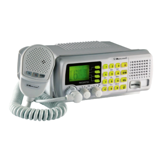
Manual Notes Writing of this manual has been completed with the intention of supplying information that is comprehensive, precise and up-to-date. Nevertheless, Midland does not assume responsibility for the actual correspondence with the product and for the consequences of possible errors caused by factors over which it has no control. - Page 6 INTRODUCTION 2.1 General Congratulations for choosing Midland’s REGATTA™ 2 marine transceiver. This product is a high performance, mobile VHF DSC marine transceiver. The following are its principle features: Equipped with all international channels available (correctly assigned). High transmission power of 25W, which allows the user to maintain contact from large distances, and a low transmission power of 1 W to reduce power consumption during short-distance communication and for in harbor use.
-
Page 7: Description Of Controls And Connectors
The Distress function, or any other DSC transmission function, is not operative until a MMSI user code has been inserted. Turns REGATTA 2 on/off and regulates audio volume reception. The radio is turned off when you completely rotate the knob counter-clockwise until it clicks. -
Page 8: Back Panel (Connections)
Back panel (connections) Warning! Faulty connections or short-circuits may seriously damage REGATTA 2. Before attempting any connections, consult the specialized sections of this manual. Antenna Jack This SO 239 jack is for connecting an appropriate antenna. Power cable This red/black cable has to be connected to a power source of 12 V DC (red is positive. -
Page 9: Microphone
Microphone (1) UP and DOWN buttons These two buttons change the tuning channel. The first scrolls upwards through the tuned marine channels, the second scrolls downwards. (2) Button 16 For ease of use, button 16 performs the same function as button 16 on the front panel of the transceiver. -
Page 10: Installation
(e.g. compass) in order to avoid interference during their use. (15) GPS receiver connecting cable (not shown) Allows for accessibility to the front panel of REGATTA 2. Provides easy connection to a power supply, for the antenna and for other (16) Operator Warning Label (not shown) cables. -
Page 11: Mounting The Transceiver
6. Align the transceiver on the bracket, ensuring the holes of the internal part of the bracket line up with those on both sides of the transceiver (you can choose the preferred notch in order to best adjust the angle of the transceiver’s front 4.3 Mounting the transceiver panel for ease of viewing and use (15 of variation for each notch). -
Page 12: Installation Of The Antenna/Electromagnetic Exposure
4.5 Installation of the antenna/electromagnetic exposure For optimal radio settings and minimal user exposure to electromagnetic radio frequency energy, ensure that: The antenna is connected to the transceiver and is properly installed. The antenna is situated away from people and is positioned at least three feet from the transceiver and microphone. -
Page 13: Connections
Never short-circuit it, as this may damage the radio. 4.7.b GPS device If your REGATTA 2 transceiver is connected to a GPS receiver, you can obtain and view NMEA information relative to the current position the vessel (latitude and longitude) and the local time with respect to Greenwich Mean Time (GMT). -
Page 14: Basic Operation
Regulations require that some channels operate on low transmission power (see Chap.1) LCD display. For this reason, REGATTA 2 automatically switches to low power when these channels are selected. If no signal is being received (only noise), slowly rotate the SQ knob clockwise, stopping as soon as the noise and RX disappear stably. -
Page 15: Selecting High And Low Transmission Power
When the transceiver is tuned to a channel limited to low output power, pressing the H/L button has no effect. In the standard mode, REGATTA 2 switches 25 W during high power output and 1 Watt during low power output. Only on channels 15 and 17 the radio always reduces automatically - according to the international agreements for maritime radio –... -
Page 16: Scanning Functions
Dual Watch and Triple Watch Before the scanning automatically starts again, REGATTA 2 waits for a few seconds in case the user wishes, if necessary, to respond to a call even if in truth you will see The meaning of these terms are: the channels being scanned. -
Page 17: Memory Channels (Mem Mode)
Transmission: It is possible to transmit at any time, also when the scanning is Dual/Triple Watch cannot function correctly if the squelch is not correctly regulated, as active. In that case REGATTA 2 will always transmit on channel 16; if instead described in par .5.3 the transmission is done after a signal has been found, the device will transmit on the previously busy channel. -
Page 18: Use With Gps
Navigating the DSC menu Customized setup REGATTA 2 offers many DSC functions. For this reason it was created a specific menu of settings and activations accessible via the function keys as follows: Some GPS receivers may require a change in the manner the radio processes the Access the “CALL”-Menu by pressing the related function key. -
Page 19: Sending An Individual Call
CH06. You can carry out an individual call using the following procedure: To confirm the reception of the received message, REGATTA 2 will emit an acoustic Press briefly the function key corresponding to message that can be interrupted by pressing the function key corresponding to ”OK” or CALL. -
Page 20: General Call To All Ships (All Ship Safety - All Ship Urgency)
Like mentioned above, it is possible, to insert manually the address of who is If you don’t want to carry out the call (because of errors), press the 16 button or desired to call (using the alphanumerical keypad), or to select one of the the “C”-button to leave the menu. - Page 21 I. LISTING L. SINKING M. ADRIFT To send out the distress call hold down the DISTRESS-button for 5 seconds. An acoustic alert will emit and the distress call will be carried out on channel 70 even when the channel is in use. After the distress call, the transceiver will simultaneously check channel 70 and channel 16 on a receipt of DSC confirmation and meanwhile appears following: At this point:...
-
Page 22: Receiving A Dsc Call
Every time REGATTA 2 receives a call (distress, individual or general) an entry will be stored in the list of registered calls “LOG”. -
Page 23: Customization
You can insert into the directory the MMSI codes from frequently called stations, by REGATTA 2 can carry out a series of settings in order to personalize the transceiver giving them a name (e.g. vessel or owner). Then you can search and use them to your requirements and to insert the necessary data to its operation. -
Page 24: Lcd" (Display Contrast)
The insertion of time coordinates is required to carry out DSC calls. If REGATTA 2 is connected to a compatible GPS receiver (GPS 200) the setting of these data is not... -
Page 25: Zone"(Adjustment Of Utc Time Deviation)
Confirm by pressing one of the following buttons: C , 16, function key DSC, or your approved vendor for a complete reset. PTT. This setting remains stored on the Eeprom, therefore REGATTA 2 will maintain the same 11 MAINTENANCE settings when the radio is turned on again. -
Page 26: Troubleshooting
Other interference devices Move other interference (televisions, computers, devices further from transceivers, etc.) too close to REGATTA 2 REGATTA 2 Impossible to Some channels operate only on Tune to another channel transmit or use high low power or are only for reception... -
Page 27: Technical Specifications
13 TECHNICAL SPECIFICATIONS: Channels ............All 48USA, 55 Canadian & 57 international marine channels, Frequency generation....................... PLL synthesizer Frequency range ..................TX from 156.025 to 157.425 MHz ........................RX from 156.050 to 162.550 MHz Antenna Impedance ..........................50 Ohm Power supply.............................12 VDC Operating temperature ..................... from -20°C to +55°C Size (HxLxW).......................... -
Page 28: Frequency Table
14 Frequency Table Channel Number Frequency MHz INT CAN US Mode Note INT CAN US Mode Note 157.100 161.700 22A 22A 157.100 157.100 156.050 160.650 157.150 161.750 01A 156.050 156.050 23A 157.150 157.150 156.100 160.700 24 157.200 161.800 156.150 160.750 25 157.250 161.850 156.200... - Page 29 INT CAN US Mode Note 156.925 161.525 78A 78A 156.925 156.925 156.975 161.575 79A 79A 156.975 156.975 157.025 161.625 80A 80A 157.025 157.025 157.075 161.675 81A 81A 157.075 157.075 157.125 161.725 82A 82A 157.125 157.125 157.175 161.775 83A 83A 157.175 157.175 84 157.225 161.825...