D-Link Express Ethernetwork DI-704P User Manual
Broadband router with print server
Hide thumbs
Also See for Express Ethernetwork DI-704P:
- Manual (73 pages) ,
- User manual (47 pages) ,
- Quick installation manual (17 pages)
Table of Contents
Advertisement
Quick Links
Download this manual
See also:
Owner's Manual
Advertisement
Table of Contents

Related Manuals for D-Link Express Ethernetwork DI-704P


Summary of Contents for D-Link Express Ethernetwork DI-704P
- Page 1 D-Link DI-704P Express Ethernetwork Broadband Router with Print Server Manual Building Networks for People...
-
Page 2: Table Of Contents
Contents Package Contents ................3 Introduction....................4 Features and Benefits ................5 LEDs ....................6 Connections ..................7 Introduction to Broadband Technology ...........8 Sample Scenario ................10 Network Setup ..................11 Setup Wizard ..................12 Using the Configuration Menu..............17 Networking Basics ................62 Reset ....................90 Technical Specifications ..............91 Contacting Technical Support ..............92 Warranty and Registration ..............93... -
Page 3: Package Contents
If any of the above items are missing, please contact your reseller. WARNING! Using a power supply with a different voltage rating than the one included with the DI-704P will cause damage and void the warranty for this product. System Requirements for Configuration:... -
Page 4: Introduction
Print Server software included is for Windows Operating Systems only. Postscript Level 1 and 2 printers can be connected to the DI-704P for Macintosh OS 9.x or X computers. The DI-704P does not support non-Postscript printers with Macintosh OS. -
Page 5: Features And Benefits
Print Server software included is for Windows Operating Systems only. Postscript Level 1 and 2 printers can be connected to the DI-704P for Macintosh OS 9.x or X computers. The DI-704P does not support non-Postscript printers with Macintosh OS. -
Page 6: Leds
A solid light indicates a proper connection to Power the power supply. Flashes consistently to indicate that the M1 LED DI-704P is working properly. Solid light indicates that Internet connec- M2 LED tion has been established. A Solid light indicates connection on the WAN port. -
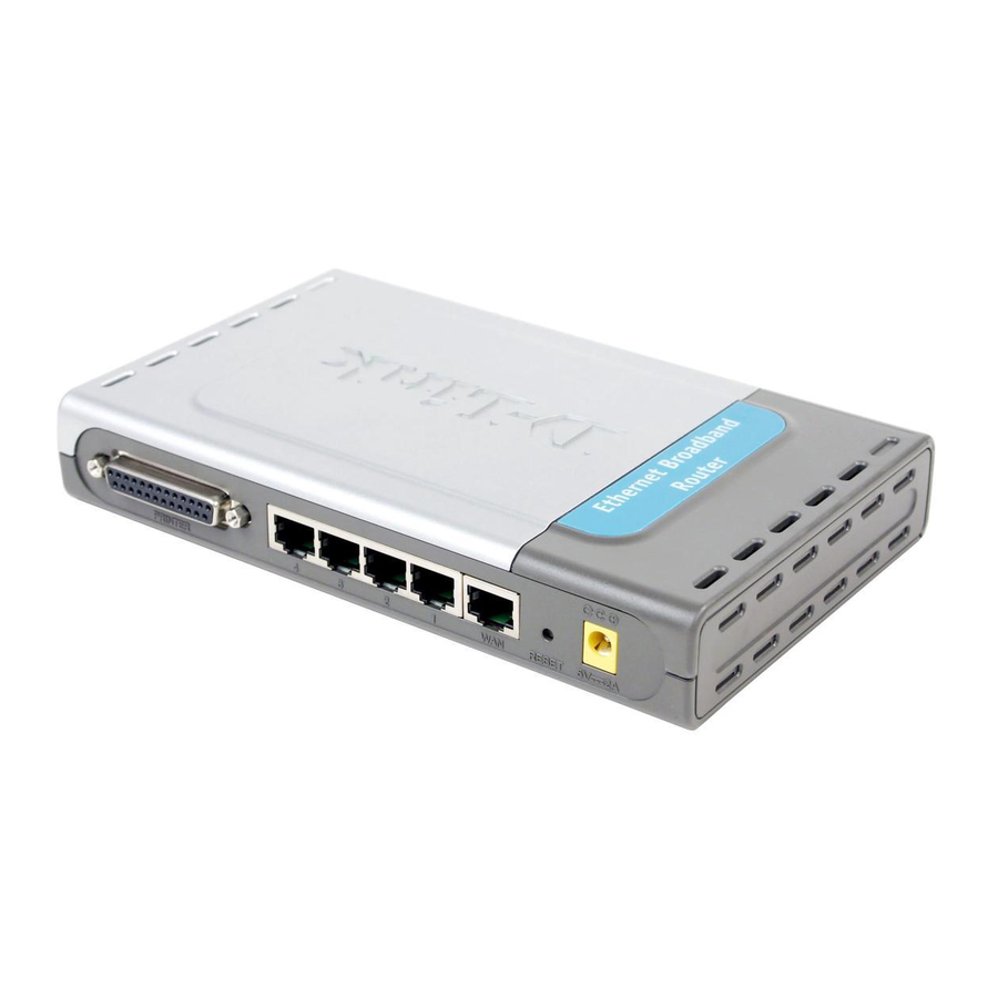
Page 7: Connections
LAN port is where you would connect each Lan Ports computer to your network. WARNING! Using a power supply with a different voltage rating than the one included with the DI-704P will cause damage and void the warranty for this product. -
Page 8: Introduction To Broadband Router Technology
Introduction to Broadband Router Technology A router is a device that forwards data packets from a source to a destination. Routers can work on Open System Interconnection (OSI) layer 3, which for- wards data packets using an IP address and not a MAC address. A router will forward data from the Internet to a particular computer on your LAN. -
Page 9: Introduction To Local Area Networking
Introduction to Local Area Networking Local Area Networking (LAN) is the term used when connecting several com- puters together over a small area such as a building or group of buildings. LAN’s can be connected over large areas. A collection of LANs connected over a large area is called a Wide Area Network (WAN). -
Page 10: Sample Scenario
Quick Installation Guide included with the DFE-690TXD.) Connect your printer to the printer port on the DI-704P. Please refer to the quick installation guide for loading the print server software. ** Easily upgrade to a wireless network by adding a wireless Access Point (D-Link DWL-900AP+) **... -
Page 11: Network Setup
B. Turn OFF your computer. C. Do NOT connect the power adapter to your D-Link router. Connect the D-Link Router Cables. A. Connect the Ethernet (or networking) cable from the Cable or DSL modem to the WAN port of the router. -
Page 12: Setup Wizard
Using the Setup Wizard Open your Web browser and type “http://192.168.0.1” into the URL address box. Then press the Enter or Return key. The logon pop-up screen will appear. Type “admin” for the username and leave the password field blank. Click Once you have logged in, the Home screen will appear. - Page 13 Using the Setup Wizard (continued) You will see the following screens Click Next Set up your new password. You have the option to establish a password. Click Next...
- Page 14 Using the Setup Wizard (continued) Set up your Time Zone. have the option to the set standard time for your router. To change the default selection, select the drop down arrow and chose the correct time zone. Click Next Select your Internet Connection.
- Page 15 Using the Setup Wizard (continued) If you selected Dynamic IP Address, this screen will appear: (Used mainly for Cable Internet service.) Click the “Clone MAC Address” button to automatically copy the MAC address of the network adapter in your computer. You can also manually type in the MAC address.
- Page 16 Using the Setup Wizard (continued) If your ISP uses PPPoE (Point-to-Point Protocol over Ethernet), and this option is selected, then this screen will appear: (Used mainly for DSL Internet service.) Please be sure to remove any existing PPPoE client software installed on your computers.
-
Page 17: Using The Configuration Menu
Type in the IP Address of the DI-704P Home > Wizard Note: if you have changed the default IP Address assigned to the DI-704P, make sure to enter the correct IP Address. The factory default User name is “admin” and the default Password is blank (empty). - Page 18 Using the Configuration Menu (continued) Home > Wizard (continued) The Home>Wizard screen will appear. Please refer to the Quick Installation Guide for more information regarding the Setup Wizard. Clicking Apply will save changes made to the page Clicking Cancel will clear changes made to the page Clicking Help will bring up helpful information regarding the page Clicking Restart will restart the router.
- Page 19 Using the Configuration Menu (continued) Home > WAN (continued) WAN is short for Wide Area Network. The WAN settings can be referred to as the Public settings. All IP information in the WAN settings are public IP addresses which are accessible on the Internet. The WAN settings consist of four options: Dynamic IP Address, Static IP Address, PPPoE, and Others.
- Page 20 Using the Configuration Menu (continued) Home > WAN (continued) MAC Address: The default MAC address is set to the WAN’s physical interface MAC address on the Broadband Router. You can use the “Clone MAC Address” button to copy the MAC address of the Ethernet Card installed by your ISP and replace the WAN MAC address with this MAC address.
- Page 21 Using the Configuration Menu (continued) Home > WAN > Static IP Address Choose Static IP Address if all WAN IP information is provided to you by your ISP. You will need to enter in the IP Address, subnet mask, gateway address, and DNS address(es) provided to you by your ISP.
- Page 22 Home > WAN > PPPoE Please be sure to remove any Client Software program on your computer before you start your configuration of the DI-704P Router. Choose PPPoE (Point to Point Protocol over Ethernet) if your ISP uses PPPoE connection. Your ISP will provide you with a username and password.
- Page 23 Using the Configuration Menu (continued) Home > WAN > PPPoE (continued) Dynamic PPPoE: PPPoE connection where you will receive an IP address automatically from your ISP Static PPPoE: PPPoE connection where you have an assigned (static) IP address User Name: Your PPPoE username provided by your ISP Password: Your PPPoE password provided by your ISP...
- Page 24 Using the Configuration Menu (continued) Home > WAN > PPTP Dynamic IP Address for PPTP is a WAN connection used in Europe. My IP Address: Enter in the IP address for the My Subnet Mask: Enter the subnet mask information. Server IP: Enter the Server IP address.
- Page 25 Using the Configuration Menu (continued) Home > WAN > PPTP (continued) PPTP Account: Enter in the username for the PPTP account PPTP Password: Enter the password for the PPTP account. Retype in Password to confirm Connection ID: (Optional) enter the Connection ID if required Maximum Idle Time: The amount of time of inactivity before disconnecting your PPPoE session.
- Page 26 Using the Configuration Menu (continued) Home > WAN > BigPond Cable Dynamic IP Address for BigPond is a WAN connection used in Australia. Account: Enter in the username for the BigPond account Password: Enter the password for the BigPond account Login Server: (Optional) enter the Login Server name if required Auto-reconnect:...
- Page 27 LAN is short for Local Area Network. This is considered your internal network. These are the IP settings of the LAN interface for the DI-704P. These settings may be referred to as Private settings. You may change the LAN IP address if needed. The LAN IP address is private to your internal network and cannot be seen on the Internet.
- Page 28 Using the Configuration Menu (continued) Home > DHCP DHCP stands for Dynamic Host Control Protocol. The DI-704P has a built-in DHCP server. The DHCP Server will automatically assign an IP address to the computers on the LAN/private network. Be sure to set your computers to be DHCP clients by setting their TCP/IP settings to “Obtain an IP Address Automatically.”...
- Page 29 Using the Configuration Menu (continued) Home > DHCP Static DHCP allows computers on the LAN to receive the same DHCP IP address everytime it boots up. You can bind a specific IP address to a specific computer based on the computer’s MAC address Starting IP address: The starting IP address for the DHCP server’s IP assignment.
- Page 30 LAN network so all computers networked with the DI-704P are invisible to the outside world. If you wish, you can make some of the LAN computers accessible from the Internet by enabling Virtual Server. Depending on the requested service, the DI-704P edirects the external service request to the appropriate server within the LAN network.
- Page 31 Using the Configuration Menu (continued) Advanced > Virtual Server The DI-704P is also capable of port-redirection meaning incoming traffic to a particular port may be redirected to a different port on the server computer. Each virtual services that are created will be listed at the bottom of the screen in the Virtual Servers List.
- Page 32 Using the Configuration Menu (continued) Advanced > Virtual Server Example #2: If you have an FTP server that you wanted Internet users to access by WAN port 2100 and only during the weekends, you would need to enable it as such. FTP server is on LAN computer 192.168.0.30.
- Page 33 Internet telephony and others. These applications have difficulties working through NAT (Network Address Translation). Special Applications makes some of these applications work with the DI-704P. If you need to run applications that require multiple connections, specify the port normally associated with an application in the Trigger field, then enter the public ports associated with the trigger port into the Incoming Ports field.
- Page 34 Using the Configuration Menu (continued) Advanced > Application At the bottom of the screen, there are already defined special applications. To use them, select one from the drop down list and select an ID number you want to use. Then click the “Copy to” button and the router will fill in the appropriate information to the list.
- Page 35 Using the Configuration Menu (continued) Advanced > IP Filter Use IP (Internet Protocol) filters to allow or deny computers access to the Internet based on their IP address.
- Page 36 Using the Configuration Menu (continued) Advanced > IP Filter Enabled or Disabled: Click Enabled to apply the filter policy or click Disabled to enter an inactive filter policy (You can reactivate the policy later.) IP Address: Enter in the IP address range of the computers that you want the policy to apply to. If it is only a single computer that you want the policy applied to, then enter the IP address of that computer in the Start Source IP and leave the End Source IP blank.
- Page 37 At the bottom of the screen, there is a list of MAC addresses from the DHCP client computers connected to the DI-704P. To use them, select one from the drop down list and select an IP number you want to use. Then click the “Copy to” button and the DI-...
- Page 38 Using the Configuration Menu (continued) Advanced > MAC Filters Disabled MAC Filter: Select this option if you do not want to use MAC filters on your Local Area Network (LAN). Only allow computers with MAC address listed below to access the network: Select this option to allow only computers that are in the list access to the network and Internet.
- Page 39 Using the Configuration Menu (continued) Advanced > URL Blocking Use URL Blocking filters to disallow computer(s) to access Internet with the following URL keywords entered into the list. The URL Blocking filters are useful feature and similar to parental control. Users can enter keywords that may have adult content, hack, or other materials to prevent computers connected to the Local Area Network (LAN) from accessing those web sites.
- Page 40 Advanced > Domain Filter Use Domain filters to allow or deny computers access to specific Internet domains whether it is through www, ftp, snmp, etc. Domain filters apply to wired computers connected to one of the four Ethernet LAN ports to the DI-704P.
- Page 41 Using the Configuration Menu (continued) Advanced > Domain Filter Disabled Domain Filter: Select this option if you do not want to use Domain filters. Allow users to access the following domains and block all other domains: Select this option to allow users to access the specified Internet domains listed below.
- Page 42 Broadband Router. It works in the same way as IP Filters with additional settings. You can create more detailed access rules for the DI-704P. When virtual services are created and enabled, it will also display in Firewall Rules. Firewall Rules contains all network firewall rules pertaining to IP (Internet Protocol).
- Page 43 SNMP (Simple Network Management Protocol) is a widely used network monitoring and control protocol that reports activity on each network device to the administrator of the network. SNMP can be used to monitor traffic and statistics of the DI-704P. The DI- 704P supports SNMP v1.
- Page 44 DDNS (Dynamic Domain Name System) keeps dynamic IP addresses (e.g., IP addresses assigned by a DHCP capable router or server) linked to a domain name. Users who have a Dynamic DNS account may use this feature on the DI-704P. DDNS: When an IP address is automatically assigned by a DHCP server, DDNS automatically updates the DNS server.
- Page 45 Using the Configuration Menu (continued) Advanced > Routing Static routes can be added if you require specific routes within your internal network. These routes will not apply to the WAN (Internet) network. Destination: Enter in the IP of the specified network that you want to access using the static route. Subnet Mask: Enter in the subnet mask to be used for the specified network.
- Page 46 If you have a computer that cannot run Internet applications properly from behind the DI-704P, then you can allow that computer to have unrestricted Internet access. Enable this feature and enter the IP address of that computer as a DMZ (Demilitarized Zone) host with unrestricted Internet access.
- Page 47 Tools > Admin Admininstrator Settings At this page, the DI-704P administrator can change the system password. There are two accounts that can access the Broadband Router’s Web-Management interface. They are admin and user. Admin has read/write access while user has read-only...
- Page 48 Broadband Router and 8080 is the port used for the Web-Management interface. Tools > Time The system time is the time used by the DI-704P for scheduling services. You can manually set the time or connect to a NTP (Network Time Protocol) server. If an NTP...
- Page 49 The current system settings can be saved as a file onto the local hard drive. The saved file or any other saved setting file created by the DI-704P can be uploaded into the unit. To reload a system settings file, click on Browse to search the local hard drive for the file to be used.
- Page 50 Using the Configuration Menu (continued) Tools > Firmware You can upgrade the firmware by using this tool. First, check the D-Link support site for firmware updates at http://support.dlink.com. Make sure that the firmware you want to use is saved on the local hard drive of your computer. Click on Browse to search the local hard drive for the firmware that you downloaded from the D-Link website to be used for the update.
- Page 51 Using the Configuration Menu (continued) Tools > Misc...
- Page 52 Block WAN Ping: Click Enable to block the WAN ping. Computers on the Internet will not get a reply back from the DI-704P when it is being “ping”ed. This may help to increase security. SPI Mode: Stateful Packet Inspection is a form of firewall protection that will inspect all of the pack- ets transmitted through the DI-704P.
- Page 53 Renew to connect to your ISP. If your WAN connection is set up for PPPoE, a Connect button and Disconnect button will be displayed. Use Disconnect to drop the PPPoE connection and use Connect to establish the PPPoE connection. This page allows you to observe the DI-704P’s working status:...
- Page 54 Using the Configuration Menu (continued) Status > Device Info LAN MAC Address: Displays the LAN port MAC/hardware address IP Address: LAN/Private IP Address of the DI-704P Subnet Mask: LAN/Private Subnet Mask of the DI-704P WAN MAC Address: Displays the WAN port MAC/hardware address...
- Page 55 Using the Configuration Menu (continued) Status > Log The Broadband Router keeps a running log of events and activities occurring on the Router. If the device is rebooted, the logs are automatically cleared. You may save the log files under Log Settings. First Page: The first page of the log.
- Page 56 E-Mail Alert: The DI-704P can be set up to send the log files to a specific email address. SMTP Server IP: Input the SMTP information information. Usually, this is offered by your Internet service provider (ISP).
- Page 57 Using the Configuration Menu (continued) Help Help This menu displays the complete Help menu. For help at anytime, click on the Help tab in the configuration menu.
-
Page 58: Installing The Print Server Software
Installing the Print Server Software Insert the installation CD-ROM into the CD-ROM drive. The following window will be shown automatically. If it is not, please run “install.exe” on the CD-ROM. Click Install Print Server Software Click Next... - Page 59 Installing the Print Server Software (continued) Select the destination folder. Click Browse select a destination folder Click Next Click Finish Select the option for restarting the computer. Click After rebooting your computer, the software installation procedure is finished.
- Page 60 Configuring on Windows 98SE/ME Platforms After you finish the software installation proce- dure, your computer will be capable of network printing provided by the DI-704P. On a Windows 95/98 platform, open the Printers window in the My Computer menu. Now, you can configure the print server of...
- Page 61 Configuring on Windows XP/2000/NT Platforms Type in the IP address of the DI-704P. Click Click Port The configuration procedure for a Windows 2000/XP platform is similar to that of Win- dows 95/98 except the screen of printer Prop- erties: Click...
-
Page 62: Networking Basics
Networking Basics Using the Network Setup Wizard in Windows XP In this section you will learn how to establish a network at home or work, using Microsoft Windows XP. Note: Please refer to websites such as http://www.homenethelp.com http://www.microsoft.com/windows2000 for information about networking computers using Windows 2000, ME or 98SE. - Page 63 Networking Basics Please follow all the instructions in this window: Click Next In the following window, select the best description of your computer. If your computer connects to the internet through a gateway/router, select the second option as shown. Click Next...
- Page 64 Networking Basics Enter a Computer description and a Computer name (optional.) Click Next Enter a Workgroup name. All computers on your network should have the same Workgroup name. Click Next...
- Page 65 Networking Basics Please wait while the Network Setup Wizard applies the changes. When the changes are complete, click Next. Please wait while the Network Setup Wizard configures the computer. This may take a few minutes.
- Page 66 Networking Basics In the window below, select the option that fits your needs. In this example, Create a Network Setup Disk has been selected. You will run this disk on each of the computers on your network. Click Next. Insert a disk into the Floppy Disk Drive, in this case drive A. Format the disk if you wish, and click Next.
- Page 67 Networking Basics Please read the information under Here’s how in the screen below. After you com- plete the Network Setup Wizard you will use the Network Setup Disk to run the Network Setup Wizard once on each of the computers on your network. To continue click Next.
- Page 68 Networking Basics Please read the information on this screen, then click Finish to complete the Network Setup Wizard. The new settings will take effect when you restart the computer. Click Yes to restart the computer. You have completed configuring this computer. Next, you will need to run the Network Setup Disk on all the other computers on your network.
- Page 69 Networking Basics Naming your Computer To name your computer, please follow these directions:In Windows XP: Click Start (in the lower left corner of the screen) Right-click on My Computer Select Properties and click Select the Computer Name Tab in the System Properties window.
-
Page 70: Checking The Ip Address In Windows Xp
Networking Basics Naming your Computer In this window, enter the Computer name Select Workgroup and enter the name of the Workgroup All computers on your network must have the same Workgroup name. Click OK Checking the IP Address in Windows XP The wireless adapter-equipped computers in your network must be in the same IP Address range (see Getting Started in this manual for a definition of IP Address Range.) To check on the IP Address of the adapter, please do the following:... - Page 71 Networking Basics Checking the IP Address in Windows XP This window will appear. Click the Support tab Click Close Assigning a Static IP Address in Windows XP/2000 Note: Residential Gateways/Broadband Routers will automatically assign IP Ad- dresses to the computers on the network, using DHCP (Dynamic Host Configura- tion Protocol) technology.
- Page 72 Networking Basics Assigning a Static IP Address in Windows XP/2000 Double-click on Network Connections Right-click on Local Area Connections Double-click on Properties...
- Page 73 192.168.0.2 Subnet Mask: 255.255.255.0 Default Gateway: Enter the LAN IP address of the wireless router. (D-Link wireless routers have a LAN IP address of 192.168.0.1) Select Use the following DNS server address. Enter the LAN IP address of the Wireless Router.
- Page 74 Networking Basics Selecting a Dynamic IP Address with Macintosh OSX Go to the Apple Menu and se- lect System Preferences Click on Network Select Built-in Ethernet in the Show pull-down menu Select Using DHCP in the Configure pull-down menu Click Apply Now The IP Address, Subnet mask, and the Router’s IP Address will appear in a...
- Page 75 Networking Basics Checking the Wireless Connection by Pinging in Windows XP and 2000 Go to Start > Run > type cmd. A window similar to this one will appear. Type ping xxx.xxx.xxx.xxx, where xxx is the IP Address of the Wireless Router or Access Point.
-
Page 76: Adding A Local Printer
Networking Basics Adding and Sharing Printers in Windows XP After you have run the Network Setup Wizard on all the computers in your network (please see the Network Setup Wizard section at the beginning of Networking Basics,) you can use the Add Printer Wizard to add or share a printer on your network. - Page 77 Networking Basics Adding a local printer (a printer connected directly to a computer) A printer that is not shared on the network and is connected directly to one computer is called a local printer. If you do not need to share your printer on a network, follow these directions to add the printer to one computer.
- Page 78 Networking Basics Adding a local printer Click Next Select Local printer attached to this computer (Deselect Automati- cally detect and install my Plug and Play printer if it has been selected.) Click Next Select Use the following port: From the pull-down menu select the correct port for your printer...
- Page 79 Networking Basics Adding a local printer Select and highlight the correct driver for your printer. Click Next (If the correct driver is not displayed, insert the CD or floppy disk that came with your printer and click Have Disk.) At this screen, you can change the name of the printer (optional.)
- Page 80 Networking Basics Adding a local printer This screen gives you information about your printer. Click Finish When the test page has printed, Click OK...
- Page 81 Networking Basics Adding a local printer Go to Start> Printers and Faxes A successful installation will display the printer icon as shown at right. You have successfully added a local printer. Sharing a network printer After you have run the Network Setup Wizard on all the computers on your network, you can run the Add Printer Wizard on all the computers on your network.
- Page 82 Networking Basics Sharing a network printer Click on Add a printer Click Next Select Network Printer Click Next...
- Page 83 Networking Basics Sharing a network printer Select Browse for a printer Click Next Select the printer you would like to share Click Next Click Finish...
- Page 84 Networking Basics Sharing a network printer To check for proper installation: Go to Start > Printers and Faxes The printer icon will appear at right, indicating proper installation. You have completed adding the printer. To share this printer on your network: Remember the printer name...
- Page 85 Networking Basics Sharing an LPR printer To share an LPR printer (using a print server,) you will need a Print Server such as the DP-101P+. Please make sure that you have run the Network Setup Wizard on all the computers on your network. To share an LPR printer, please follow these directions: Go to Start >...
- Page 86 Networking Basics Sharing an LPR printer Select Create a new port From the pull-down menu, select Standard TCP/IP Port, as shown. Click Next Please read the instructions on this screen Click Next Enter the Printer IP Address and the Port Name, as shown.
- Page 87 Networking Basics Sharing an LPR printer In this screen, select Custom Click Settings Enter the Port Name and the Printer Name or IP Address Select LPR Enter a Queue Name (if your Print-Server/ Gateway has more than one port, you will need a Queue name.) Click OK...
- Page 88 Networking Basics Sharing an LPR printer This screen will show you information about your printer. Click Finish Select the printer you are adding from the list of Printers. Insert the printer driver disk that came with your printer. Click Have Disk If the printer driver is already in- stalled, do the following: Select Keep...
- Page 89 Networking Basics Sharing an LPR printer You can rename your printer if you choose. It is optional. Please remember the name of your printer. You will need this information when you use the Add Printer Wizard on the other computers on your network.
-
Page 90: Reset
After you have tried other methods for troubleshooting your network, you may choose to Reset the DI-704P to the factory default settings. To hard-reset the D-Link DI-704P to the Factory Default Settings, please do the following: Turn off the DI-704P... -
Page 91: Technical Specifications
Technical Specifications Standard IEEE 802.3 10Base-T Ethernet IEEE 802.3u 100Base-TX Fast Ethernet IEEE 802.3 NWay Auto-Negotiation VPN Pass Through PPTP L2TP IPSec Ports One WAN Four LAN LEDs Power Local Network - 10/100 Operating Temperature F to 131 F (0 C to 55 Humidity 95% maximum (non-condensing) -
Page 92: Contacting Technical Support
Technical Support You can find software updates and user documentation on the D-Link website. D-Link provides free technical support for customers within the United States and within Canada for the duration of the warranty period on this product. U.S. and Canadian customers can contact D-Link technical support through our website, or by phone. -
Page 93: Warranty And Registration
D-Link’s sole obligation shall be to repair or replace the defective Hardware during the Warranty Period at no charge to the original owner or to refund at D-Link’s sole discretion. Such repair or replacement will be rendered by D-Link at an Authorized D-Link Service Office. The replacement Hardware need not be new or have an identical make, model or part. - Page 94 D-Link. Products shall be fully insured by the customer. D-Link will not be held responsible for any packages that are lost in transit to D-Link. The repaired or replaced packages will be shipped to the customer via UPS Ground or any common carrier selected by D-Link, with shipping charges prepaid.
- Page 95 FROM THE USE OF THE PRODUCT, RELATING TO WARRANTY SERVICE, OR ARISING OUT OF ANY BREACH OF THIS LIMITED WARRANTY, EVEN IF D-LINK HAS BEEN ADVISED OF THE POSSIBILITY OF SUCH DAMAGES. THE SOLE REMEDY FOR A BREACH OF THE FOREGOING LIMITED WARRANTY IS REPAIR, REPLACEMENT OR REFUND OF THE DEFECTIVE OR NON-CONFORMING PRODUCT.