Advertisement
Quick Links
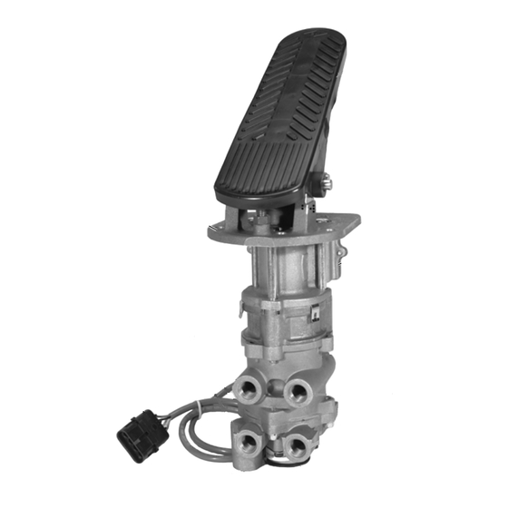
®
Bendix
®
E-10PR
MOUNTING
PLATE
SUPPLY
4 PORTS
ELECTRICAL
CONNECTOR
AUXILIARY
FIGURE 1 - E-10PR
™
RETARDER CONTROL BRAKE
VALVE
DESCRIPTION
Refer to Figures 3 and 4 for item numbers referenced in
parenthesis.
®
™
The Bendix
E-10PR
retarder control brake valve is used
with retarder systems installed on automatic transmissions.
Automatic transmission retarders are used to retard forward
motion of the vehicle above 5 mph. Retarders are most
popular in the transit (buses/coaches) industry and are used
to extend the life of brake system components.
The retarder system is actuated early in the brake
application, before air pressure is delivered.
Retarders can be installed either internally or externally on
the automatic transmission and are generally electrically
activated by devices such as the E-10PR
retarders redirect the flow of hydraulic fluid through the torque
converter while others use a small internal brake in the output
section of the transmission.
™
Retarder Control Brake Valve
TREADLE
RETARDER
CONTROL
SECTION
VALVE
DELIVERY
4 PORTS
EXHAUST
™
valve. Most
™
The E-10PR
valve is capable of controlling up to a three-
stage retarder (different levels of retardation) through the
sequencing of its three electrical switches. The sequencing
of these switches is important to the proper operation of the
retarder.
E-10PR
™
retarder control brake valve is a floor mounted,
treadle operated type brake valve with two separate supply
and delivery circuits for service (primary and secondary)
braking, which provides the driver with a graduated control
for applying and releasing the vehicle brakes.
™
The E-10PR
valve uses a metal coil spring (6) housed in an
upper body assembly. The use of a metal coil spring (and
the upper body assembly) provides greater treadle travel
and, therefore, provides the driver with a less sensitive "feel"
when making a brake application. The E-10PR
control brake valve is generally used on buses, where smooth
brake applications contribute to passenger comfort.
The circuits in the E-10PR
are identified as follows: The No. 1 or primary circuit is that
portion of the valve between the spring seat which contacts
the plunger and the relay piston; the No. 2 or secondary
circuit is that portion between the relay piston and the
exhaust cavity.
The primary circuit of the valve is similar in operation to a
standard single circuit air brake valve and under normal
operating conditions the secondary circuit is similar in
operation to a relay valve.
Both primary and secondary circuits of the brake valve use
a common exhaust protected by an exhaust diaphragm.
OPERATION
- Refer to Figure 2
APPLYING: NORMAL OPERATION - NO. 1 OR
PRIMARY CIRCUIT PORTION
When the brake treadle is depressed, the plunger exerts
force on the spring seat (5), graduating spring (12), and
primary piston (11). The primary piston, which contains the
exhaust valve seat, closes the primary exhaust valve. As
the exhaust valve closes, the primary inlet valve is moved off
its seat allowing primary air to flow out the No. 1 or primary
delivery port.
™
retarder
™
retarder control brake valves
1
Advertisement

Related Manuals for BENDIX E-10PR RETARDER CTRL BRAKEVALVE


Summary of Contents for BENDIX E-10PR RETARDER CTRL BRAKEVALVE
- Page 1 ® ™ The Bendix E-10PR retarder control brake valve is used Both primary and secondary circuits of the brake valve use with retarder systems installed on automatic transmissions.
- Page 2 ™ MV-3 MANIFOLD ™ TP-5 TRACTOR VALVE PROTECTION VALVE TRAILER CONTROL VALVE SLACK SPRING ADJUSTER BRAKES BRAKE CHAMBER SLACK ADJUSTER ™ (E-10PR RETARDER QUICK CONTROL BRAKE RELEASE VALVE VALVE DOUBLE CHECK VALVE GOVERNOR AIR DRYER BP-R1 ™ BOBTAIL PROPORTIONING VALVE SUPPLY RESERVOIR (WET TANK)
- Page 3 (11) equals Apply a thin layer of Barium grease, per BW-204-M (Bendix the effort exerted by the driver's foot on the treadle. A balanced part 246671), between plunger and mounting plate – do not...
-
Page 4: Leakage Check
Figures 3 and 4 and note that the lock nut (7) and with genuine Bendix parts available at authorized Bendix stem (22) are used to contain the primary piston return parts outlets. - Page 5 FIGURE 4 - E-10PR ™ RETARDER CONTROL BRAKE VALVE - EXPLODED VIEW...
-
Page 6: Cleaning And Inspection
Dow (18). Torque to 5 - 10 inch pounds. Corning 55 o-ring lubricant (Bendix piece number 291126). INSTALLATION OF THE RETARDER CONTROL Note: All torques specified in this manual are assembly... -
Page 7: Valve Installation
CALIBRATION OF MICRO SWITCHES ON ALL TREADLE VALVE INSTALLATION ACTUATED BRAKE VALVES (Except the lever actuated 1. Install the assembled brake valve on the vehicle. model) See Figure 5. 2. Reconnect all air lines to the valve using the identification NOTE: Cannon connector pins are identified with numbers made during VALVE REMOVAL step 1. -
Page 8: Personal Injury Or Death
EXTREME CAUTION should to their proper operating condition. be used to prevent personal injury resulting from contact with moving, rotating, leaking, heated or electrically charged components. BW2159 © 2004 Bendix Commercial Vehicle Systems LLC. All rights reserved. 3/2004 Printed in U.S.A.