Table of Contents
Advertisement
Quick Links
T41 HD Setup Manual
FCC Information and Copyright
This equipment has been tested and found to comply with the limits of a Class
B digital device, pursuant to Part 15 of the FCC Rules. These limits are designed
to provide reasonable protection against harmful interference in a residential
installation. This equipment generates, uses, and can radiate radio frequency
energy and, if not installed and used in accordance with the instructions, may
cause harmful interference to radio communications. There is no guarantee
that interference will not occur in a particular installation.
The vendor makes no representations or warranties with respect to the
contents here and specially disclaims any implied warranties of merchantability
or fitness for any purpose. Further the vendor reserves the right to revise this
publication and to make changes to the contents here without obligation to
notify any party beforehand.
Duplication of this publication, in part or in whole, is not allowed without first
obtaining the vendor's approval in writing.
The content of this user's manual is subject to be changed without notice and
we will not be responsible for any mistakes found in this user's manual. All the
brand and product names are trademarks of their respective companies.
Advertisement
Table of Contents
Troubleshooting

Related Manuals for Biostar T41 HD


Summary of Contents for Biostar T41 HD
- Page 1 T41 HD Setup Manual FCC Information and Copyright This equipment has been tested and found to comply with the limits of a Class B digital device, pursuant to Part 15 of the FCC Rules. These limits are designed to provide reasonable protection against harmful interference in a residential installation.
-
Page 2: Table Of Contents
Table of Contents Chapter 1: Introduction ............1 Before You Start..................1 Package Checklist ..................1 Motherboard Features................2 Rear Panel Connectors................3 Motherboard Layout................. 4 Chapter 2: Hardware Installation ..........5 Installing Central Processing Unit (CPU) ..........5 FAN Headers....................7 Installing System Memory ................ -
Page 3: Chapter 1: Introduction
T41 HD CHAPTER 1: INTRODUCTION EFORE TART Thank you for choosing our product. Before you start installing the motherboard, please make sure you follow the instructions below: Prepare a dry and stable working environment with sufficient lighting. Always disconnect the computer from power outlet before operation. -
Page 4: Motherboard Features
Motherboard Manual OTHERBOARD EATURES SPEC LGA 775 Supports Hyper-Threading / Execute Disable Bit / Intel Core2Duo / Core2Quad / Celeron 4xx Enhanced Intel SpeedStep® / Intel Architecture-64 / / Pentium Dual-core / Celeron Dual-core Extended Memory 64 Technology / Virtualization processor Technology 800 / 1066 / 1333 MHz... -
Page 5: Rear Panel Connectors
Provide Audio-In/Out and microphone connection Board Size 210 (W) x 305 (L) mm Biostar reserves the right to add or remove support for OS Support Windows 2000 / XP / Vista 32 / Vista 64 any OS with or without notice... -
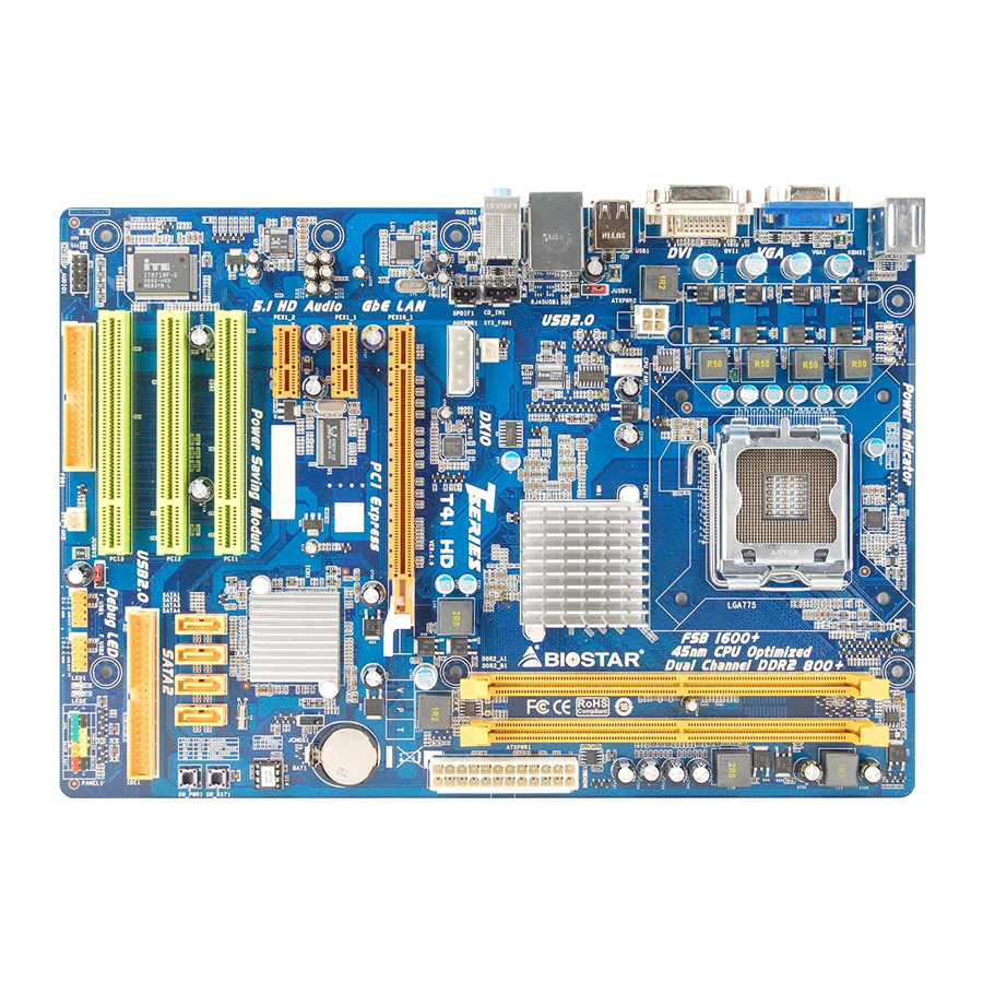
Page 6: Motherboard Layout
Motherboard Manual OTHERBOARD AYOUT KBMS1 LGA775 CPU1 ATXPWR2 USB1 CPU_FAN1 Intel JUSBV1 G4 1 A3 RJ45USB1 CD_IN1 AUDIO1 SYS_FAN1 AUXPWR1 SPDIF1 ATXPWR1 PEX16_1 BAT1 PEX1_1 Intel ICH7 JCMOS1 PEX1_2 CODEC BIOS PCI1 SATA1 SATA3 SW _RST1 SW _PW R1 PCI2 Super SATA2 SATA4... -
Page 7: Chapter 2: Hardware Installation
T41 HD CHAPTER 2: HARDWARE INSTALLATION (CPU) NSTALLING ENTRAL ROCESSING Special Notice: Remove Pin Cap before installation, and make good preservation for future use. When the CPU is removed, cover the Pin Cap on the empty socket to ensure pin legs won’t be damaged. Pin Cap Step 1: Pull the socket locking lever out from the socket and then raise the lever up to a 90-degree angle. - Page 8 Motherboard Manual Step 2: Look for the triangular cut edge on socket, and the golden dot on CPU should point forwards this triangular cut edge. The CPU will fit only in the correct orientation. Step 2-1: Step 2-2: Step 3: Hold the CPU down firmly, and then lower the lever to locked position to complete the installation.
-
Page 9: Fan Headers
T41 HD FAN H EADERS These fan headers support cooling-fans built in the computer. The fan cable and connector may be different according to the fan manufacturer. Connect the fan cable to the connector while matching the black wire to pin#1. -
Page 10: Installing System Memory
Motherboard Manual NSTALLING YSTEM EMORY A. Memory Modules Unlock a DIMM slot by pressing the retaining clips outward. Align a DIMM on the slot such that the notch on the DIMM matches the break on the Slot. Insert the DIMM vertically and firmly into the slot until the retaining chip snap back in place and the DIMM is properly seated. - Page 11 T41 HD B. Memory Capacity DIMM Socket Total Memory DDR Module Location Size DDR2_A1 256MB/512MB/1GB/2GB Max is 4GB. DDR2_B1 256MB/512MB/1GB/2GB C. Dual Channel Memory installation Please refer to the following requirements to activate Dual Channel function: Install memory module of the same density in pairs, shown in the table. Dual Channel Status DDR2_A1 DDR2_B1 Disabled Disabled...
-
Page 12: Connectors And Slots
Motherboard Manual ONNECTORS AND LOTS FDD1: Floppy Disk Connector The motherboard provides a standard floppy disk connector that supports 360K, 720K, 1.2M, 1.44M and 2.88M floppy disk types. This connector supports the provided floppy drive ribbon cables. IDE1: Hard Disk Connector The motherboard has a 32-bit Enhanced PCI IDE Controller that provides PIO Mode 0~4, Bus Master, and Ultra DMA 33/66/100 functionality. - Page 13 T41 HD SATA1~SATA4: Serial ATA Connectors The motherboard has a PCI to SATA Controller with 4 channels SATA interface. It satisfies the SATA 2.0 spec and with transfer rate of 3.0Gb/s. Assignment Ground Ground Ground AUXPWR1: Auxiliary Power for Graphics This connector is an auxiliary power connection for graphics cards.
- Page 14 Motherboard Manual ATXPWR1: ATX Power Source Connector This connector allows user to connect 24-pin power connector on the ATX power supply. Assignment Assignment +3.3V +3.3V -12V +3.3V Ground Ground PS_ON Ground Ground Ground Ground Ground PW_OK Standby Voltage+5V +12V +12V Ground +3.3V ATXPWR2: ATX Power Source Connector...
- Page 15 T41 HD PEX16_1: PCI-Express x16 Slot PCI-Express 1.0a compliant. Maximum theoretical realized bandwidth of 4GB/s simultaneously per direction, for an aggregate of 8GB/s totally. PEX1_1/PEX1_2: PCI-Express x1 Slots PCI-Express 1.0a compliant. Maximum theoretical realized bandwidth of 250MB/s simultaneously per direction, for an aggregate of 500MB/s totally. PCI-Express supports a raw bit-rate of 2.5GB/s on the data pins.
-
Page 16: Chapter 3: Headers & Jumpers Setup
Motherboard Manual CHAPTER 3: HEADERS & JUMPERS SETUP OW TO ETUP UMPERS The illustration shows how to set up jumpers. When the jumper cap is placed on pins, the jumper is “close;” if not, that means the jumper is “open”. Pin opened Pin closed Pin1-2 closed... -
Page 17: Clear Cmos Procedures
T41 HD F_USB1/F_USB2: Headers for USB 2.0 Ports at Front Panel These headers allow user to connect additional USB cable on the PC front panel. They also can be connected with internal USB devices, like USB card reader. Assignment +5V (fused) +5V (fused) USB- USB-... -
Page 18: Cd-Rom Audio-In Connector
Motherboard Manual F_AUDIO1: Front Panel Audio Header This header allows user to connect the front audio output cable with the PC front panel. This header allows only HD audio front panel connector; AC’97 connector is not acceptable. Assignment Mic Left in Ground Mic Right in GPIO... - Page 19 T41 HD SPDIF1: Digital Audio-out Connector This connector allows user to connect the PCI bracket SPDIF output header. Assignment SPDIF_OUT Ground JUSBV1/JUSBV2: Power Source Headers for USB Ports Pin 1-2 Close: JUSBV1: +5V for USB ports at USB1/RJ45USB1. JUSBV2: +5V for USB ports at front panel (F_USB1/F_USB2). Pin 2-3 Close: JUSBV1: +5V STB for USB ports at USB1/RJ45USB1.
- Page 20 Motherboard Manual On-Board LED Indicators There are 6 LED indicators on the motherboard showing system status. LED1 & LED2: Debug Indicators PH1 ~ PH4: Power Status Indicators Please refer to the tables below for specific messages: LED1 LED2 Message Normal Memory Error VGA Error Abnormal: CPU / Chipset error.
-
Page 21: Chapter 4: T-Series Bios & Software
T41 HD CHAPTER 4: T-SERIES BIOS & SOFTWARE BIOS ERIES T-Series BIOS Features Overclocking Navigator Engine (O.N.E.) Memory Integration Test (M.I.T., under Overclock Navigator Engine) BIO-Flasher: Update BIOS file from USB Flash Drive or FDD Self Recovery System (S.R.S) Smart Fan Function CMOS Reloading Program !! WARNING !! For better system performance, the BIOS firmware is being... - Page 22 Motherboard Manual Manual Overclock System (M.O.S.) MOS is designed for experienced overclock users. It allows users to customize personal overclock settings. BIOS SETUP UTILITY PCIPnP Boot Main Advanced Chipset T-Series Exit T-Series Settings Options WARNING: Please Clear CMOS if system no display Normal after overclocking.
-
Page 23: Dram Frequency
T41 HD PCIE Clock By It helps increase VGA card performance. PCIE Frequency Setting It helps increase VGA card performance. FSB(Bsel) To NorthBridge Latch This item allows you to select the FSB Frequency. DRAM Frequency For better system performance, sometimes downgrading the memory frequency is necessary when CPU frequency is over the upper limit. - Page 24 Motherboard Manual V6 Tech Engine This engine will make a good over-clock performance. BIOS SETUP UTILITY Main Advanced PCIPnP Boot Chipset T-Series Exit T-Series Settings Options WARNING: Please Clear CMOS if system no display Normal after overclocking. Automate OverClock Manual OverClock OverClock Navigator [Automate OverClock] =========== Automate OverClock System ===========...
- Page 25 T41 HD Notices: Not all types of Intel CPU perform above overclock setting ideally; the difference will be based on the selected CPU model. B. Memory Integration Test (M.I.T.) This function is under “Overclocking Navigator Engine” item. MIT allows users to test memory compatibilities, and no extra devices or software are needed.
- Page 26 Motherboard Manual C. BIO-Flasher BIO-Flasher is a BIOS flashing utility providing you an easy and simple way to update your BIOS via USB pen drive or floppy disk. The BIO-Flasher is built in the BIOS chip. To enter the utility, press <F12> during the Power-On Self Tests (POST) procedure while booting up.
- Page 27 T41 HD D. Self Recovery System (S.R.S.) This function can’t be seen under BIOS setup; and is always on whenever the system starts up. However, it can prevent system hang-up due to inappropriate overclock actions. When the system hangs up, S.R.S. will automatically log in the default BIOS setting, and all overclock settings will be re-configured.
- Page 28 Motherboard Manual Smart Fan Calibration Choose this item and then the BIOS will automatically test and detect the CPU/System fan functions and show CPU/System fan speed. Control Mode This item provides several operation modes of the fan. Fan Ctrl OFF(℃) If the CPU/System temperature is lower than the set value, the CPU/ System fan will turn off.
-
Page 29: T-Series Software
T41 HD ERIES OFTWARE Installing T-Series Software 1. Insert the Setup CD to the optical drive. The drivers installation program would appear if the Autorun function has been enabled. 2. Select Software Installation, and then click on the respective software title. - Page 30 Motherboard Manual eHot-Line (Optional) eHot-Line is a convenient utility that helps you to contact with our Tech-Support system. This utility will collect the system information which is useful for analyzing the problem you may have encountered, and then send these information to our tech-support department to help you fix the problem. Before you use this utility, please set Outlook Express as your default e-mail client application program.
- Page 31 If you are not using Outlook Express as your default e-mail client application, you may need to save the system information to a .txt file and send the file to our tech support with other e-mail application. Go to the following web http://www.biostar.com.tw/app/en-us/about/contact.php for getting our contact information.
-
Page 32: Bios Update
Motherboard Manual BIOS Update BIOS Update is a convenient utility which allows you to update your motherboard BIOS under Windows system. Show current BIOS information AWARD BIOS AMI BIOS Clear CMOS function (Only for AWARD BIOS) Save current BIOS to a .bin file Update BIOS with a BIOS file <Backup BIOS>... - Page 33 T41 HD <Update BIOS> Before doing this, please download the proper BIOS file from the website. For AWARD BIOS, update BIOS procedure should be run with Clear CMOS function, so please check on Clear CMOS first. Then click Update BIOS button, a dialog will show for asking you backup current BIOS.
-
Page 34: Chapter 5: Useful Help
Motherboard Manual CHAPTER 5: USEFUL HELP RIVER NSTALLATION After you installed your operating system, please insert the Fully Setup Driver CD into your optical drive and install the driver for better system performance. You will see the following window after you insert the CD The setup guide will auto detect your motherboard and operating system. -
Page 35: Extra Information
T41 HD XTRA NFORMATION CPU Overheated If the system shutdown automatically after power on system for seconds, that means the CPU protection function has been activated. When the CPU is over heated, the motherboard will shutdown automatically to avoid a damage of the CPU, and the system may not power on again. -
Page 36: Ami Bios Beep Code
Motherboard Manual AMI BIOS B Boot Block Beep Codes Number of Beeps Description No media present. (Insert diskette in floppy drive A:) “AMIBOOT.ROM” file not found in root directory of diskette in Insert next diskette if multiple diskettes are used for recovery Flash Programming successful File read error No Flash EPROM detected... -
Page 37: Troubleshooting
T41 HD ROUBLESHOOTING Probable Solution No power to the system at all Make sure power cable is Power light don’t illuminate, fan securely plugged in. inside power supply does not turn Replace cable. Contact technical support. Indicator light on keyboard does not turn on. -
Page 38: Appendix: Spec In Other Languages
Motherboard Manual APPENDIX: SPEC IN OTHER LANGUAGES ERMAN Spezifikationen LGA 775 Unterstützt Hyper-Threading / Execute Disable Bit / Intel Core2Duo / Core2Quad / Celeron 4xx Enhanced Intel SpeedStep® / Intel Architecture-64 / / Pentium Dual-core / Celeron Dual-core Extended Memory 64 Technology / Virtualization Prozessoren Technology 800 / 1066 / 1333 MHz... - Page 39 DVI-D-Anschluss LAN-Anschluss USB-Anschluss Audioanschluss Platinengröße 210 mm (B) X 305 mm (L) Biostar behält sich das Recht vor, ohne Ankündigung OS-Unterstüt Windows 2000 / XP / Vista 32 / Vista 64 die Unterstützung für ein Betriebssystem zung hinzuzufügen oder zu entfernen.
-
Page 40: French
Motherboard Manual RENCH SPEC LGA 775 Prend en charge les technologies Hyper-Threading / Processeurs Intel Core2Duo / Core2Quad d'exécution de bit de désactivation / Intel SpeedStep® / Celeron 4xx / Pentium Dual-core / optimisée/ d'architecture Intel 64 / de mémoire Celeron Dual-core étendue 64 / de virtualisation Bus frontal 800 / 1066 / 1333 MHz... - Page 41 Dimensions 210 mm (l) X 305 mm (H) de la carte Biostar se réserve le droit d'ajouter ou de supprimer le Support SE Windows 2000 / XP / Vista 32 / Vista 64 support de SE avec ou sans préavis.
-
Page 42: Italian
Motherboard Manual TALIAN SPECIFICA LGA 775 Supporto di Hyper-Threading / Execute Disable Processore Intel Core2Duo / Bit / Enhanced Intel SpeedStep® / Architettura Core2Quad / Celeron 4xx / Pentium Intel 64 / Tecnologia Extended Memory 64 / Dual-core / Celeron Dual-core Tecnologia V irtualization 800 / 1066 / 1333 MHz Intel G41 A3... - Page 43 Connettore audio Dimension 210 mm (larghezza) x 305 mm i scheda (altezza) Sistemi Biostar si riserva il diritto di aggiungere o Windows 2000 / XP / Vista 32 / Vista operativi rimuovere il supporto di qualsiasi sistema supportati operativo senza preavviso.
-
Page 44: Spanish
Motherboard Manual PANISH Especificación LGA 775 Admite Hyper-Threading / Bit de deshabilitación de Procesador Intel Core2Duo / Core2Quad / ejecución / Intel SpeedStep® Mejorado / Intel Celeron 4xx / Pentium Dual-core / Celeron Architecture-64 / Tecnología Extended Memory 64 / Dual-core Tecnología de virtualización 800 / 1066 / 1333 MHz... - Page 45 210 mm. (A) X 305 Mm. (H) la placa Soporte de Biostar se reserva el derecho de añadir o retirar el sistema Windows 2000 / XP / Vista 32 / Vista 64 soporte de cualquier SO con o sin aviso previo.
-
Page 46: Portuguese
Motherboard Manual ORTUGUESE ESPECIFICAÇÕES LGA 775 Suporta as tecnologias Hyper-Threading / Execute Processador Intel Core2Duo / Disable Bit / Enhanced Intel SpeedStep® / Intel Core2Quad / Celeron 4xx / Pentium Arquitecture -64 / Extended Memory 64 / Virtualization Dual-core / Celeron Dual-core 800 / 1066 / 1333 MHz Intel G41 A3 Chipset... - Page 47 Tamanho 210 mm (L) X 305 mm (A) da placa Sistemas A Biostar reserva-se o direito de adicionar ou remover operativos Windows 2000 / XP / Vista 32 / Vista 64 suporte para qualquer sistema operativo com ou sem suportados...
-
Page 48: Polish
Motherboard Manual OLISH SPEC LGA 775 Obsługa Hyper-Threading / Execute Disable Bit / Procesor Intel Core2Duo / Core2Quad / Enhanced Intel SpeedStep® / Intel Architecture-64 / Procesor Celeron 4xx / Pentium Dual-core / Celeron Extended Memory 64 Technology / Virtualization Dual-core Technology 800 / 1066 / 1333 MHz... - Page 49 Port LAN Port USB Gniazdo audio Wymiary 210 mm (S) X 305 mm (W) płyty Obsluga Biostar zastrzega sobie prawo dodawania lub systemu Windows 2000 / XP / Vista 32 / Vista 64 odwoływania obsługi dowolnego systemu operacyjne operacyjnego bez powiadomienia.
-
Page 50: Russian
Motherboard Manual USSIAN СПЕЦ LGA 775 Поддержка технологий Hyper-Threading / Execute (центральн Процессор Intel Core2Duo / Core2Quad / Disable Bit / Enhanced Intel SpeedStep® / Intel ый Celeron 4xx / Pentium Dual-core / Celeron Architecture-64 / Extended Memory 64 Technology / процессор) Dual-core технологии... - Page 51 Гнездо для подключения наушников Размер 210 мм (Ш) X 305 мм (В) панели Biostar сохраняет за собой право добавлять или Поддержка Windows 2000 / XP / Vista 32 / Vista 64 удалять средства обеспечения для OS с или без предварительного уведомления.
-
Page 52: Arabic
Motherboard Manual RABIC اﻟﻤﻮاﺻﻔﺎت ﺗﺪﻋﻢ ﺗﻘﻨﻴﺎتHyper-Threading / Execute Disable Bit / LGA 775 Enhanced Intel SpeedStep® / Intel Architecture-64 / ﻣﻌﺎﻟﺠﺎتIntel Core2Duo / Core2Quad / اﻟﻤﻌﺎﻟﺠﺔ وﺣﺪة Extended Memory 64 Technology / Virtualization Celeron 4xx / Pentium Dual-core / اﻟﻤﺮآﺰیﺔ Technology Celeron Dual-core ﺼﻞ... - Page 53 ﻋﺪد ﺵﺒﻜﺔ اﺗﺼﺎل ﻣﺤﻠﻴﺔ ﻣﻨﻔﺬ ﻋﺪد ﻣﻨﺎﻓﺬ ﻋﺪد ﻣﻘﺒﺲ ﺹﻮت ارﺗﻔﺎع ﻣﻢ ﻋﺮض ﻣﻢ اﻟﻠﻮﺣﺔ ﺣﺠﻢ ﺗﺤﺘﻔﻆBiostar ﺑﺪون أو ﺑﺈﺧﻄﺎر ﺗﺸﻐﻴﻞ ﻧﻈﺎم ﻷي اﻟﺪﻋﻢ إزاﻟﺔ أو إﺿﺎﻓﺔ ﻓﻲ ﺑﺤﻘﻬﺎ Windows 2000 / XP / Vista 32 / Vista 64 اﻟﺘﺸﻐﻴﻞ...
-
Page 54: Japanese
Motherboard Manual APANESE 仕様 LGA 775 Hyper-Threading / Execute Disable Bit / Enhanced Intel Intel Core2Duo / Core2Quad / Celeron 4xx SpeedStep® / Intel Architecture-64 / Extended / Pentium Dual-core / Celeron Dual-core Memory 64 Technology / Virtualization Technologyをサ processor ポートします... - Page 55 ネクタ システムファンヘッダ システムファン電源装置 CMOSクリアヘッダ 各コネクタは2つのフロントパネルUSBポートをサポートし USBコネクタ ます シリアルポートコネクタ 電源コネクタ(24ピン) 電源コネクタ(4ピン) PS/2キーボード PS/2マウス VGAポート 背面パネル DVI-Dポート LANポート USBポート オーディオジャック ボードサイズ 210 mm (幅) X 305 mm (高さ) Biostarは事前のサポートなしにOSサポートを追加または削 OSサポート Windows 2000 / XP / Vista 32 / Vista 64 除する権利を留保します。 2009/05/18...