Desa H.S.I. Owner's Manual
Desa portable forced air heaters owner's manual h.s.i.
Hide thumbs
Also See for H.S.I.:
- Owner's manual (40 pages) ,
- Owner's manual (17 pages) ,
- Owner's manual (30 pages)
Table of Contents
Advertisement
For more information, visit www.desatech.com
For more information, visit www.desatech.com
Heater Sizes: 40,000 55,000 60,000 70,000 110,000 115,000
150,000 155,000 165,000 and 200,000 Btu/Hr Models
IMPORTANT: Read and understand this manual before assembling, starting or servicing
heater. Improper use of heater can cause serious injury. Keep this manual for future reference.
TABLE OF CONTENTS
SAFETY INFORMATION ............................................................ 2
PRODUCT IDENTIFICATION ..................................................... 3
UNPACKING ............................................................................... 3
THEORY OF OPERATION ......................................................... 4
FUELS ......................................................................................... 4
VENTILATION ............................................................................. 4
ASSEMBLY ................................................................................. 5
OPERATION ............................................................................... 5
OPERATION WITH PORTABLE GENERATOR .......................... 6
PREVENTATIVE MAINTENANCE SCHEDULE ......................... 6
STORING, TRANSPORTING, OR SHIPPING ............................ 6
Fill In For Your Records
Model No. ___________________
(Located on side panel)
Serial No. ___________________
(Located on fuel tank)
Date of Purchase: ______________
H.S.I. Series
Save this manual for future reference.
Save this manual for future reference.
PORTABLE FORCED
AIR HEATERS
TM
OWNER'S MANUAL
TROUBLESHOOTING ................................................................ 7
SERVICE PROCEDURES .......................................................... 8
TECHNICAL SERVICE ............................................................. 15
REPLACEMENT PARTS .......................................................... 15
SPECIFICATIONS .................................................................... 16
WIRING DIAGRAMS ................................................................. 16
ILLUSTRATED PARTS BREAKDOWN AND PARTS LIST ....... 18
WHEELS AND HANDLES ........................................................ 24
ACCESSORIES ........................................................................ 25
WARRANTY AND REPAIR SERVICE ...................................... 26
®
Advertisement
Table of Contents

Related Manuals for Desa H.S.I.


Summary of Contents for Desa H.S.I.
-
Page 1: Table Of Contents
For more information, visit www.desatech.com For more information, visit www.desatech.com Heater Sizes: 40,000 55,000 60,000 70,000 110,000 115,000 150,000 155,000 165,000 and 200,000 Btu/Hr Models IMPORTANT: Read and understand this manual before assembling, starting or servicing heater. Improper use of heater can cause serious injury. Keep this manual for future reference. TABLE OF CONTENTS SAFETY INFORMATION ... -
Page 2: Safety Information
SAFETY INFORMATION SAFETY INFORMATION WARNINGS IMPORTANT: Read this owner’s manual carefully and completely before trying to assemble, operate, or ser- vice this heater. Improper use of this heater can cause serious injury or death from burns, fire, explosion, electrical shock, and carbon monoxide poisoning. DANGER: Carbon monoxide poisoning may lead to death! Early signs of carbon monoxide... -
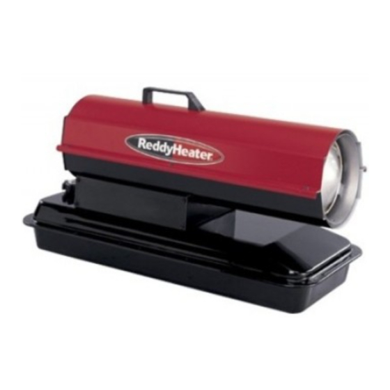
Page 3: Product Identification
PRODUCT IDENTIFICATION Handle Hot Air Outlet Upper Shell Lower Shell Fuel Tank Side Cover Ignition Control Assembly (On Inside of Side Cover) Power Cord Fuel Cap Figure 1 - 40/55/60/70 Models Hot Air Outlet Upper Shell Lower Shell Fuel Side Cover Ignition Control Assembly (On Inside Power Cord... -
Page 4: Theory Of Operation
THEORY OF OPERATION FUELS VENTILATION THEORY OF OPERATION The air pump forces air through the air line. The air The Fuel System: is then pushed through the nozzle. This air causes fuel to be lifted from the tank. A fine mist of fuel is sprayed into the combustion chamber. The Air System: The motor turns the fan. -
Page 5: Assembly
ASSEMBLY (FOR 110/115/150/155/165/200 MODELS ONLY) These models are furnished with wheels and a rear handle. Some models are furnished with a front handle also. Wheels, handle(s), and the mounting hardware are found in the shipping carton. Tools Needed • Medium Phillips Screwdriver •... -
Page 6: Operation With Portable Generator
OPERATION WITH PORTABLE GENERATOR STORING, TRANSPORTING, OR SHIPPING PREVENTATIVE MAINTENANCE SCHEDULE OPERATION WITH PORTABLE GENERATOR WARNING: Before operating heater or any appli- ance from a portable generator, verify that generator has been properly connected to earth ground. Im- proper grounding or failure to ground generator can result in electrocution if a ground fault occurs. -
Page 7: Troubleshooting
TROUBLESHOOTING WARNING: Never service heater while it is plugged in, operating, or hot. Severe burns and electrical shock can occur. FAULT CONDITION Motor does not start five seconds after heater is plugged in Motor starts and runs but heater does not ignite Heater ignites but ignition control as- sembly shuts heater off after a short... -
Page 8: Service Procedures
SERVICE PROCEDURES SERVICE PROCEDURES WARNING: To avoid risk of burn and electrical shock, never attempt to service heater while it is plugged in, operating, or hot. UPPER SHELL REMOVAL 1. Remove screws along each side of heater using 5/16" nut-driver. These screws attach upper and lower shells together. - Page 9 SERVICE PROCEDURES Continued PUMP PRESSURE ADJUSTMENT Remove pressure gauge plug from filter end cover (see Figure 13). Install accessory pressure gauge (part number HA1180). Start heater (see Operation, page 5). Allow motor to reach full speed. Adjust pressure. Turn relief valve to right to increase pressure. Turn relief valve to left to decrease pressure.
- Page 10 SERVICE PROCEDURES SERVICE PROCEDURES Continued (For 200 Model Only) Remove side cover screws using 5/16" nut-driver. Remove side cover (see Figure 17). Pull lower fuel line off the fuel valve fitting (see Figure 17). Note: See Figure 16, page 9 if your model does not come equipped with a fuel valve.
- Page 11 SERVICE PROCEDURES Continued IGNITOR Remove upper shell and fan guard (See Upper Shell Removal, page 8). Remove fan (see page 8). Remove 4 side cover screws with a 5/16" nut driver. Remove side cover (see Figures 15 or 16, page 9 or Figure 17, page 10). Disconnect ignitor wires from ignition control assembly (see Figure 19).
-
Page 12: Nozzle Assembly
SERVICE PROCEDURES SERVICE PROCEDURES Continued NOZZLE ASSEMBLY (For 40/55/60/70/110/115/150/155/165 Models Only) Remove upper shell (see Upper Shell Removal, page 8). Remove fan (see Fan, page 8). Remove fuel and air line hoses from nozzle assembly (see Fig- ure 21, 22, or 23). Turn nozzle assembly 1/4 turn to left and pull toward motor to remove (see Figure 24). - Page 13 SERVICE PROCEDURES Continued (For 200 Model Only) Remove combustion chamber and ignitor by following steps 1 through 7 under Ignitor, page 11. Carefully place the ignitor in a safe location. Remove two nozzle adapter bracket screws (see Figure 26). Place hex-shaped aluminum nozzle adapter into vise (do not overtighten).
- Page 14 SERVICE PROCEDURES SERVICE PROCEDURES Continued PUMP ROTOR (Procedure if Rotor is Binding) Remove upper shell (see Upper Shell Removal, page 8). Remove filter end cover screws using 5/16" nut driver (see Fig- ure 29 or 30). Remove filter end cover and air filters. Remove pump plate screws using 5/16"...
-
Page 15: Technical Service
You may have further questions about installation, operation, or troubleshooting. If so, contact DESA International’s Technical Service Department at 1-866-672-6040. You can also visit DESA International’s technical services web site at www.desatech.com. REPLACEMENT PARTS Note: Use only original replacement parts. This will protect your warranty coverage for parts replaced under warranty. -
Page 16: Specifications
SPECIFICATIONS WIRING DIAGRAMS SPECIFICATIONS Model Size Output Rating (Btu/Hr) 40,000 Fuel Use only kerosene, #1/#2 diesel/fuel oil, JET A or JP-8 fuels* Fuel Tank Capacity (U.S. Gal./Liters) 3/11.3 Fuel Consumption (Gal. Per Hr/Liters Per Hr) .3/1.14 Pump Pressure (psi) Electric Requirements 120 V/60 HZ (Same All Models) Amperage (Normal Run) Motor RPM... - Page 17 WIRING DIAGRAMS Continued Blue Photocell Photocell Blue Photocell Ignitor White Motor Return White White AC Neutral (L2) Green AC Hot (L1) Thermostat Motor Ignitor (Heater with Fuel Valve Assembly) Figure 35 - Wiring Diagram with Thermostat for 200 Model Blue Photocell Blue Photocell...
-
Page 18: Illustrated Parts Breakdown And Parts List
ILLUSTRATED PARTS BREAKDOWN 40/55/60/70 Models ILLUSTRATED PARTS BREAKDOWN 40/55/60/70 MODELS Standard Thermostat Models Models R40T REM40 R55BT R55B B55BT R70DT REM60 B70DT RM60 12-1 12-2 12-3 12-18 12-17 12-16 12-5 12-15 Motor and Pump Assembly For more information, visit www.desatech.com For more information, visit www.desatech.com 12-4 12-6... -
Page 19: Parts List
PARTS LIST 40/55/60/70 MODELS PART NUMBER DESCRIPTION M51104-01 Handle 098511-67 Upper Shell (Service Part Will Be Black) M11084-29 Screw, #10-16 x 3/4" M15823-27 Screw, #10-16 x 1 098512-58 Combustion Chamber (40) 098512-50 Combustion Chamber (55/60) 098512-51 Combustion Chamber (70) M10908-2 Screw, #6-32 x 3/8"... - Page 20 ILLUSTRATED PARTS BREAKDOWN 110/115/150/155/165 Models ILLUSTRATED PARTS BREAKDOWN 110/115/150/155/165 MODELS Standard Thermostat Models Models R110B R110BT R115 B110BT REM115 SB115T RM115 SB150JT REM150E B155T REM155B R165AT RM155 R155B 10-1 10-2 10-3 10-4 10-17 10-16 10-15 10-13 10-14 Motor and Pump Assembly For more information, visit www.desatech.com For more information, visit www.desatech.com 10-5...
- Page 21 PARTS LIST 110/115/150/155/165 MODELS PART NUMBER DESCRIPTION 098511-66 Upper Shell (Service Part Will Be Black) M15823-27 Screw, #10-16 x 1/2" 098512-54 Combustion Chamber (110/115) 098512-59 Combustion Chamber (150/155) 098512-60 Combustion Chamber (165) 103971-01 Photocell Bracket (110/115) 103154-05 Photocell Bracket (150/155/165) M10908-2 Screw, #6-32 x 3/8"...
-
Page 22: Illustrated Parts Breakdown
ILLUSTRATED PARTS BREAKDOWN Standard Model R200A Thermostat Models R200AT, RM200AT, B200AT, and REM200AT ILLUSTRATED PARTS BREAKDOWN 200 MODELS 39-1 39-4 39-6 39-4 39-7 39-2 39-3 Fuel Valve Assembly (Models Equipped with Fuel Valve Only) Nozzle Assembly 7-11 10-1 10-2 10-3 10-4 10-17 10-16... - Page 23 PARTS LIST 200 MODELS PART NUMBER DESCRIPTION 107353-10 Upper Shell (Service Part Will Be Black) M15823-27 Screw, #10-16 x 1/2" 098512-69 Combustion Chamber 103154-05 Photocell Bracket M10908-2 Screw, #6-32 x 3/8" M16656-24 Photocell Assembly Burner Head Assembly 100735-13 Nozzle Assembly M10659-1 Nozzle Washer M10809-1...
-
Page 24: Wheels And Handles
WHEELS AND HANDLES 110/115/150/155/165/200 Models WHEELS AND HANDLES WHEELS AND HANDLE PARTS LIST PART PART NUMBER DESCRIPTION HA2203 Handle (110/115) HA2204 Handle (150/155/165/200) M12345-33 Screw, #10-24 x 1 M12342-3 Wheel Support Frame (110/115) M12831-3 Wheel Support Frame (150/155/165/200) NTC-3BZ Hex Nut, #10-24 107426-01 Wheel Kit (Contains 2 Wheels and Cap Nuts) -
Page 25: Accessories
Purchase accessories and parts from your nearest dealer or service center. If they can not supply these accessories or parts, either contact your nearest parts dealer or DESA International at 1-800-458-2472 for referral information. Parts Centrals are listed in the Authorized Service Center booklet supplied with heater. -
Page 26: Warranty And Repair Service
WARRANTY AND REPAIR SERVICE DESA International warrants this product and any parts thereof, to be free from defects in materials and workmanship for one (1) year from the date of first purchase when operated and maintained in accordance with instructions. This warranty is extended only to the original retail purchaser, when proof of purchase is provided.