Advertisement
Quick Links
KKM-SM-0512
MOUNTING GUIDE
FOR THE
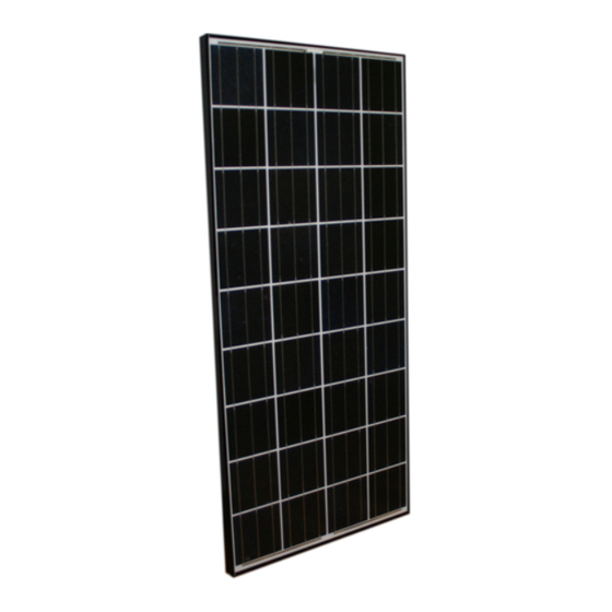
KD135SX-UPU, KD135GX-LPU~KD215GX-LPU
SOLAR PHOTOVOLTAIC POWER MODULES
Please read this guide carefully before installing the modules.
2009.12.01
KD series modules may be attached to a support structure
by the following methods. Detailed mounting method is
described in 'mounting table'.
For optimal performance in all applications, clearance
between the module frame and the mounting surface is
required to allow cooler ambient air to circulate around the
back of the module and to avoid the module and / or wiring
damage.
The minimum spacing of .6" (15 mm) is required between
PV module and the mounting surface around the perimeter
of PV module. There should also be a clearance of at
least .13" (3.2 mm) between the individual modules to allow
heat-related expansion.
BOLTING: Utilizing 5/16" or 8 mm stainless steel hardware
through the existing .35" (9 mm) diameter mounting holes in
the module frame and then through module mounting holes
on the support structure. Tighten the screws with adequate
torque (132 in-lb).
Refer to the Module Drawings for the position of the solar
module mounting holes.
CLAMPING: Fasten modules firmly with clamps using
torque values specified by structure manufacturers.
Top-down clamps must have a minimum 40mm clamping
width, and minimum 9mm overlap onto module frame.
Clamps also must not shade the sunlight incidence on glass
surface. Clamp material must be either stainless steel or
anodized aluminum.
Advertisement

Related Manuals for Kyocera KD135GX-LPU - MOUNTING GUIDE


Summary of Contents for Kyocera KD135GX-LPU - MOUNTING GUIDE
- Page 1 KKM-SM-0512 MOUNTING GUIDE FOR THE KD135SX-UPU, KD135GX-LPU~KD215GX-LPU SOLAR PHOTOVOLTAIC POWER MODULES Please read this guide carefully before installing the modules. 2009.12.01 KD series modules may be attached to a support structure by the following methods. Detailed mounting method is described in ‘mounting table’. For optimal performance in all applications, clearance between the module frame and the mounting surface is required to allow cooler ambient air to circulate around the...
- Page 2 KKM-SM-0512 <KD205GX-LPU, KD210GX-LPU, Mounting table - 1 KD215GX-LPU > Long Side Short Side Bolting 278.5mm 278.5mm 943mm 943mm 100mm 100mm 100mm 100mm 100mm 100mm 100mm 100mm 278.5mm 278.5mm 943mm 943mm 150mm 150mm 150mm 150mm Top Down 100mm 200mm 100mm 200mm Clamp Permissible clamping range...
- Page 3 KKM-SM-0512 <KD185GX-LPU> Mounting table - 2 Long Side Short Side Bolting 256.5mm 256.5mm 825mm 825mm 100mm 100mm100mm 100mm 100mm 100mm100mm 100mm 256.5mm 256.5mm 825mm 825mm 150mm 150mm 150mm 150mm Top Down 200mm 200mm 200mm 200mm Clamp Permissible clamping range 256.5mm 256.5mm 825mm 825mm...
- Page 4 KKM-SM-0512 <KD135SX-UPU, KD135GX-LPU> Mounting table - 3 Long Side Short Side Bolting 278.5mm 278.5mm 943mm 943mm 100mm 100mm 100mm 100mm 278.5mm 278.5mm 943mm 943mm 150mm 150mm 150mm 150mm Top Down Clamp 200mm 200mm Permissible clamping range 278.5mm 278.5mm 943mm 943mm 200mm 200mm 278.5mm...