Table of Contents
Advertisement
Advertisement
Table of Contents

Related Manuals for GAS GAS TXTPRO - 2009


Summary of Contents for GAS GAS TXTPRO - 2009
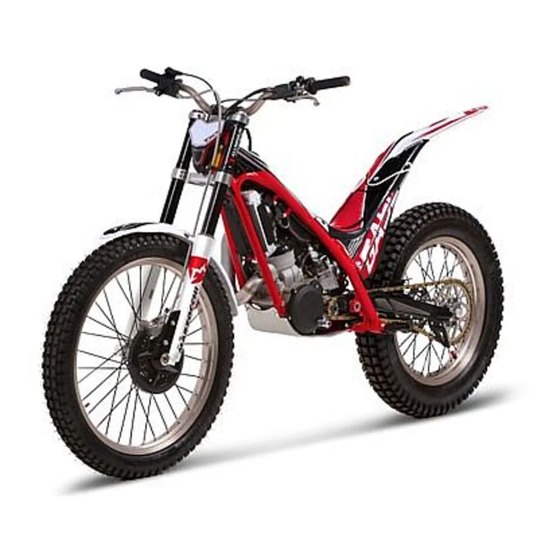
- Page 1 TXT PRO´09 TXT PRO´09...
-
Page 3: Thanks To Consumer
By choosing the new GAS GAS TXT Pro 2009 you have become part of the great GAS GAS family and, as a user of the number one manufacturer of off-road motorbike, you deserve the distinguished treatment that we wish to offer to you both in our after-sale relationship and in the explanations that we provide in this manual. -
Page 4: Important Notice
Manual. However, GAS GAS Motos, S.A. reserves the right to make modifications without any prior warning being given to consumers and without incurring any additional obligations in so doing. -
Page 5: Table Of Contents
Contents Thanks to consumer Carburettor dismantle Important notice Carburettor capacity check Warranty regulations 6 to 8 Carburettor cleaning Recommendations Inlet valves dismantle Technical specifications 10 & 11 Inlet valves Component location 12 & 13 Clutch operations Maintenance guide 14 & 15 Discs and clutch spring Serial number Air bleed... - Page 6 Warranty terms of the manufacturer GASGAS Motos, S.A. The company GAS GAS MOTOS, S.A. (hereafter referred to as “GG”), with this present document guarantees the consumer, the purchaser of a vehicle manufactured by GG, that both the materials and the manufacturing are free of defects in accordance with the highest standards of quality.
- Page 7 Obligation of the purchaser GG will have the right to reject any claims under Warranty in the event that: a) The purchaser has failed to submit the vehicle to any of the inspections and/or maintenance work required in the Users’ Manual, or has exceeded the date set for such inspections or maintenance work.
- Page 8 e) Any damages caused as a result of the defects, as well as any expenses incurred either directly or indirectly as a consequence of the defects (for example, communication costs, accommodation expenses, car hire costs, public transport costs, breakdown truck fees,, courier costs, etc.), as well as other financial losses (for example, those caused by the loss of the use of the vehicle, loss of income, time lost, etc.) f) Any acoustic or aesthetic phenomenon that does not significantly affect the condition or use of the motorcycle (for example, small or hidden imperfections, noise or vibrations that are normal in use, etc.)
-
Page 9: Recommendations
Recommendations for the good working of your GAS GAS. •Eight hours of running-in are recommended in order to guarantee the correct working of the engine. •It is important to warm the engine to the optimum working temperature every time the motorbike is used. -
Page 10: Technical Specifications 10
Digital magnetic flywheel CDI TRANSMISSION Transmission type 6 gears, Four / Six system by GAS GAS* (Patented). Clutch type Hydraulic command, 1/3 discs, variable progressive with diaphragm system by GAS GAS* (Patented). Driving system By chain Gear ratio 1st. 2,996 (35x27x28/16x24x23) 2nd. - Page 11 Primary reduction ratio 2,777 (75/27) Final reduction ratio 3,818 (42/11) Overall drive ratio 8,704 (6th. gear) Transmission oil Capacity 550 cc. Type 10W40 API SF o SG. FRAME Type Tubular profile made with Cr-Mo. Tyres Front 2,75 x 21” Trial Rear 4,00 x 18”...
-
Page 12: Component Location 12
15 16 17 18 31 32 12 Front brake disc 24 Middle silencier 1 Front fender 13 Cylinder 25 Radiator 2 Front brake caliper 14 Carburettor 26 Headlight 3 Front suspension left 15 Chain guide 27 Front tyre air valve bottle 16 Chain slide 28 Rear brake disc... - Page 13 40 41 36 Rear fender 45 Clutch lever 54 Throttle cover 37 Axis nut rear wheel 46 Light controls 55 Front brake lever 38 Left foot peg 47 Clutch pump 56 Throttle grip 39 Air filter box cover 48 Handlebar 57 Silencer 40 Shift pedal 49 Left bottle regulation...
-
Page 14: Maintenance Guide 14
The maintenance table and adjustments are easy to carry out and must be done to insure the motorcycle is in good running condition. MAINTENANCE TABLE Part Check / Adjust Replace / Clean Grease / Inspect Change Lubricate Rear shock absorver Every year Every 2 years Transmission oil... - Page 15 MAINTENANCE TABLE Part Check / Adjust Replace / Clean Grease / Inspect Change Lubricate Exhaust Every race 500 hours Exhaust silencer fiber 100 hours Air filter Every race If is damaged Every race Every cleaning Steering assembly Every race If is necessary Brake hose Every race If is necessary...
-
Page 16: Serial Number
Enter the vehicle identification number (serial The new GAS GAS number), the particulars shown on the model TXT Pro carries the label, and the ignition-key identification number a p p r o p r i a t e in the spaces provided, in order to simplify... -
Page 17: Combination Switch
The control panel includes T h e i n d i c a t o r lighting, turn signal, horn and control has been engine stop switches. located on the underside of the left-hand grip. This is an orange-colour button. To start the right-hand indicator, move this switch to the right;... -
Page 18: Steering Lock
L o c a t e d u n d e r t h e suspension lower right side Fuel tank capacity : 3,1 liters bracket. For correct operation, it is necessary Use premium gasoline with an octane rating equal to or higher to turn the handlebar completamente than that shown in the table. -
Page 19: Fuel Tank Cap
1/4 turn in counterclockwise m i x t u r e direction. To close it, place cap with the words GAS GAS in combustible fuels, the upper position, and turn the tab in clockwise direction. -
Page 20: Fuel Tap
The choke (B) is a device for aiding the engine start if this is cold. The enigne w i l l g e t g o o d temperature in a short time and it won’t damage. The idle and petrol-air mixture can be adjusted Reserve Open... -
Page 21: Kick-Start Engine Pedal Position
L i k e t h e c l u t c h 3 mm. minium lever, the front brake lever must be in the ideal position. Again, 3 mm. minium the play must not exceed 3mm, The clutch lever must be adjusted to your liking, but the free play should not This play must... -
Page 22: Oil Level Checking
When topping up the oil, open the cap (A). The engine crankcase drain cap is situated on the lower left-hand side. The drainage hole in the crankcase allows its easy emptying. To check the oil level, first make sure the motorbike is perpendicular to the ground. -
Page 23: Air Filter Box Cleaning
It is important to periodically check the air filter. Open the door set on the side of the motorbike as shown in the photo. Clean with water and detergent, then dry and lubricate with oil designed for filters. Ensure its correct collocation once clean. -
Page 24: Fuel Tank Dismantle
Remove the fuel tank, located in the upper area of the chassis, before servicing the motor or any other internal part of the motorcycle. To do this, first check that the gasoline cap and fuel cock are closed properly. Next pull out the fuel tube end (A) which is inserted in the fuel cock. -
Page 25: Spark Dismantle
It is necesassary to periodically check the spark plug condition. This must be done removing the spark plug from its housing in the upper part of the cylinder head. First disconnect the spark plug cap and remove the spark plug using an adequate wrench. Clean the spark plug with compressed air to remove dirt and prevent foreign material to enter inside the engine compartment. -
Page 26: Air Filter Box Dismantle
To carry out any type of operations on and improve access to the carburettor, it is recommended to remove the filter box. You must follow these steps: 1.- Loosen the admission port clamp. 2.- Unscrew 4 tapered Allen screws M6 which are used to anchor the filter box to the chassis. 3.- Pull the filter box straight up just enough until the rear intallation connecting fixture is visible. -
Page 27: Carburettor Dismantle
It is important to check the level of petrol within the carburettor. The float should be at 18.5mm. Fig. 3 It is necessary to clean the carburettor very thoroughly. To do so use compressed air. Extreme precautions must be taken to dry the inside of the carburettor thoroughly. -
Page 28: Inlet Valves Dismantle
The reed box assembly is composed of only one body, the Since this is the last door of access to the reeds and reed keepers. To inspect the assembly remove it by removing the 4 screws (A) attaching it to the rear of inside of the cylinder, the left and right crankcases. -
Page 29: Clutch Operations
9,75 +0.1 Check clutch discs for possible wear after Spring height of the many hours of use. For clutch stack should correct operation the minimum measure between 4,3 measure should be between 9,75 and 4,4 mm. to 9,85 mm. 17,5 After any removal or assembly operations on the clutch lifter circuit air trapped inside must... -
Page 30: Front Suspension 30
Level of air chamber Level of air chamber 180 mm. 160 mm. FRONT FORK ø 40 mm. aluminium bars 575 mm. 575 mm. (250/280/300) For a medium weight of 75 Kg. we should preload the spring to 2.5 mm -30-... -
Page 31: Rear Suspension
The front suspension The preloading of the damper spring is measured by the rotation of the is adjusted manually toothed rings (C) with the aid of a special wrench. Right (hydraulic extension). Left (hydraulic compression). The regulation is done The hidraulic brake shock absorber by turning one screw compression can be... -
Page 32: Swing-Arm Articulations
The link adjustments at the l o w e r p a r t r e a r s u s p e n s i o n m u s t b e periodically cleaned, verified and lubricated with grease. Ii is very importante to periodically remove and verify the condition of... - Page 33 Use special oil to 2) The linkage of the lubricate the following: gear shift lever. 1) All linkages of the brake and clutch levers. 4) Apply grease to 3) Also the rear brake the footrests springs p e d a l ( b e a r i n g s ) . and fixtures.
- Page 34 6) The secondary chain must 5) Apply grease to the linkage of be cleaned and lubricated the engine starting lever. thouroughly and frequently since it is exposed to inclemency and constant rubbing 7) Lubricate the handlebar with a fine coat of oil to allow smooth operation of the gasoline control.
-
Page 35: Articulation Lubrication 33 To
8) It is also recommended to Oil and clean the gas control frequently; it is frequently lubricate the chain tensor especially recommended to do so after the bike has been cleaned with water under high pressure. spring because ii is under great stress. -
Page 36: Chain Fixing Link Position
To regulate the chain slack The chain and center the rear wheel linkage must use the shaft excentrics be placed in which can be easily opposite direction of the graduated. wheel travel. The chain tension must allow a slack near the tensor of about 2 cm. -
Page 37: Tyres And Tyre Pression
Fig. 1 Fig. 2 A l l t y r e s c o n d i t i o n s must checked to insure optimum road adherence possible. Fig. 1 - Bad condition Fig. 2 - Good condition Tyre pressure should be checked periodically to insure the best road... -
Page 38: Brakes
Pad brakes wear, front and rear, must be checked from time to time to insure an efficient braking power under all circumstances. The brake calipers have been The front brake fluid level furnished with bleeder can be verified watching valves to eliminate the through the transparent air trapped in the brake inspection window. -
Page 39: Rear Brake Fluid Tank
The rear brake fluid reservoir is located at the cylinder support. Verify fluid level periodically and refill if necessary. To verify the reservoir level you must remove the fuel tank, and place de oil reservoir in horizontal position to check the real fluid level. Must be filled between the marks MIN &... -
Page 40: Torques
PART NAME PART NAME Front wheel axle 40 - 50 Spark plug Chassis to swingarm fastener 60 - 70 Ignition fasteners 7 - 8 Upper shock absorber fastener 40 - 50 Cluth fasteners 7 - 8 Lower shock absorber fastener 40 - 50 Cylinder stud bolt fasteners Connecting rods caps... -
Page 41: Storage
STORAGE For extended storage of the motorcycle, you must do the following: - Clean the motorcycle thoroughly. - Start the engine for about 5 minutes to warm up the transmission oil and then drain it (see “crankcase drain cap” page 22). - Fill with new transmission oil. - Page 42 GAS GAS MULTIFUNCTION INSTRUCTIONS The multifunction apparatus, which is waterproof, has 2 LED indicators on a central indicator screen. This central indicator screen, made of liquid crystal and with illumination, gives information about the rpm, speed, distance travelled, total kilometres travelled, time, average speed, maximum speed, ambient temperature, length of time with motor running and total time.
- Page 43 Technical characteristics FUNCTIONS SYMBOL TECHNICAL INCREMENTS PRECISION CHARACTERISTICS CURRENT SPEED SPD: - 399.9 kmph or mph 0.1 kmph or mph +/- 0,1% TACHOMETER 0 -19999 rpm 10 rpm +/- 0,1% TACHOMETER BAR -12000 rpm. Variable +/- 0,1% MAXIMUM SPEED - 399.9 kmph or mph 0.1 kmph or mph +/- 0,1% DISTANCE TRAVELLED...
- Page 44 Functions ODO: Odometer It shows the total mileage accumulated by the vehicle. The data is stored in the memory, even when the device is not running. RPM: Bar Tachometer with bar graph. The bar graph of the tachometer displays ART: Time of use controller up to 12,000 rpm.
- Page 45 Setting the multifunction display parameters After confirming each value, the display goes from one screen to the next until all have been displayed. If no button is pressed, the display returns to the home screen after 15 seconds. Activating adjustment mode Selecting the speed unit To start setting mode for the To change between kmph and...
- Page 46 Setting the time Setting the pulse per Enter the value for the time by revolution (PPR) pressing button 1 in succession. The gauge receives one To go on to the next digit, press electrical pulse for each button 3. revolution on the engine (PPR). Confirm by pressing button 2.
- Page 47 Selecting the temperature unit Selecting the warning To change the temperature temperature display between ºC and ºF, press Note: button 1. This step can only be taken on Confirm by pressing button 2. vehicles fitted with the optional temperature sensor. When the engine temperature exceeds the set value, the warning LED on the left lights up.
- Page 48 Selecting the danger rpm Total reset of the display When the set rpm is reached, the right-hand warning LED flashes to show that the rpm on Press the RESET button, using a suitable object. The display will the engine are too high. start from zero, except for the data for total accumulated distance and time.
-
Page 49: Multifunction 42 To
Screen options When the display is powered by the internal battery only, the screen lights up partially for 3 seconds when the button is pressed. If the lighting is connected to the 12V system on the vehicle, it will The multifunction display shows all the information on three different screens. -
Page 50: Troubleshooting
TROUBLESHOOTING NOTE This is not an exhaustive list of malfunctions, it only shows the most common problems. POSSIBLE CAUSE REMEDY MALFUNCTION Engine does not crank - Seized crankshaft. - Go to a specialized workshop. - Seized cylinder / piston / jornal bearing. - Go to a specialized workshop. - Page 51 MALFUNCTION POSSIBLE CAUSE REMEDY The engine operates irregularly - Ignition rotor damaged. - Replace the rotor. - Water in fuel. - Drain the fuel tank and fill up with new fuel. Engine lacks power or poor - Fuel supply defective. - Clean the fuel system and verify its operation.
- Page 52 MALFUNCTION POSSIBLE CAUSE REMEDY - Clutch does not disengage. - Go to a specialized workshop. Gears do not engage correctly - Bent or seized shift fork. - Replace the shift fork. - Gear seized at the transmission. - Go to a specialized workshop. - Damaged gearshift lever.
- Page 53 MALFUNCTION POSSIBLE CAUSE REMEDY Shock absorber set too hard - Excessive front fork oil. - Pour excess oil until reaching the correct oil level. - Front fork oil viscosity too high. - Drain fork oil and fill with correct fork oil viscosity. - Bent front fork.
- Page 54 MALFUNCTION POSSIBLE CAUSE REMEDY Handlebar vibration - Excessive steering axles tolerances. - Tighten steering bracket and steering stem locknut to the correct torque values. - Loose handlebar bracket, and loose - Tighten steering bracket and steering stem locknut to the handlebar stem locknut.
-
Page 55: Finally Recommendations
In different sections of this manual you will find data and work specifications that must be done at an autorized GAS GAS dealer, because of this and to extend the useful life of the motorcycle, all periodical inspections must be carried out by specially trained professionals at a GAS GAS Post-Sale Service Shop. -
Page 56: Homologation 56
HOMOLOGATION The vehicle you have just acquired has been homologated under the directives of the EU and complies with all the homologation requirements demanded. Compulsory homologation elements required, among others, when travelling on a public road and to meet periodical vehicle inspection approval at state controlled plants are listed below. Among other requirements, all homologation components are identified with a determined and registered mark. - Page 57 HOMOLOGATION 1 - Front right turn signal 2 - Rear right turn signal 3 - Trial rear pilot 4 - Rear left turn signal 5 - M6 Bolt 6 - ULS screw 6x16 Phillips screw M6 x 25 8- Philips screw 6.3x16 9- Front left turn signal 10- Turn signal box 11- Trial license holder homologated...