Denon AVR-989 Owner's Manual
Denon avr-989 av suround receiver owner's manual
Hide thumbs
Also See for AVR-989:
- Brochure & specs (2 pages) ,
- Code list (2 pages) ,
- Test reports (1 page)
Table of Contents
Advertisement
Quick Links
Advertisement
Table of Contents

Related Manuals for Denon AVR-989


Summary of Contents for Denon AVR-989
- Page 1 AV SURROUND RECEIVER AVR-989 Owner’s Manual...
-
Page 2: Safety Instructions
SAFETY PRECAUTIONS CAUTION RISK OF ELECTRIC SHOCK DO NOT OPEN CAUTION: TO REDUCE THE RISK OF ELECTRIC SHOCK, DO NOT REMOVE COVER (OR BACK). NO USER-SERVICEABLE PARTS INSIDE. REFER SERVICING TO QUALIFIED SERVICE PERSONNEL. The lightning flash with arrowhead symbol, within an equilateral triangle, is intended to alert the user to the presence of uninsulated “dangerous voltage”... - Page 3 2. IMPORTANT NOTICE: DO NOT MODIFY THIS PRODUCT This product, when installed as indicated in the instructions contained in this manual, meets FCC requirements. Modification not expressly approved by DENON may void your authority, granted by the FCC, to use the product. 3. NOTE This product has been tested and found to comply with the limits for a Class B digital device, pursuant to Part 15 of the FCC Rules.
-
Page 4: Table Of Contents
n Contents Getting Started Accessories ·····················································································2 Cautions on Handling ·····································································3 Cautions on Installation ·································································3 About the Remote Control Unit ····················································3 Inserting the Batteries ···································································3 Operating Range of the Remote Control Unit ································3 Part Names and Functions ····························································4 Front Panel ·····················································································4 Display ···························································································5 Rear Panel ······················································································6 Remote Control Unit ······································································7... -
Page 5: Getting Started
List of preset codes ·····························End of this manual Getting Started Thank you for purchasing this DENON product. To ensure proper operation, please read this owner’s manual carefully before using the product. After reading them, be sure to keep them for future reference. -
Page 6: Cautions On Handling
Note About the Remote Control Unit In addition to the AVR-989, the included remote control unit (RC-1105) can also be used to operate the equipment listed below. q DENON system components w Non-DENON system components •... -
Page 7: Part Names And Functions
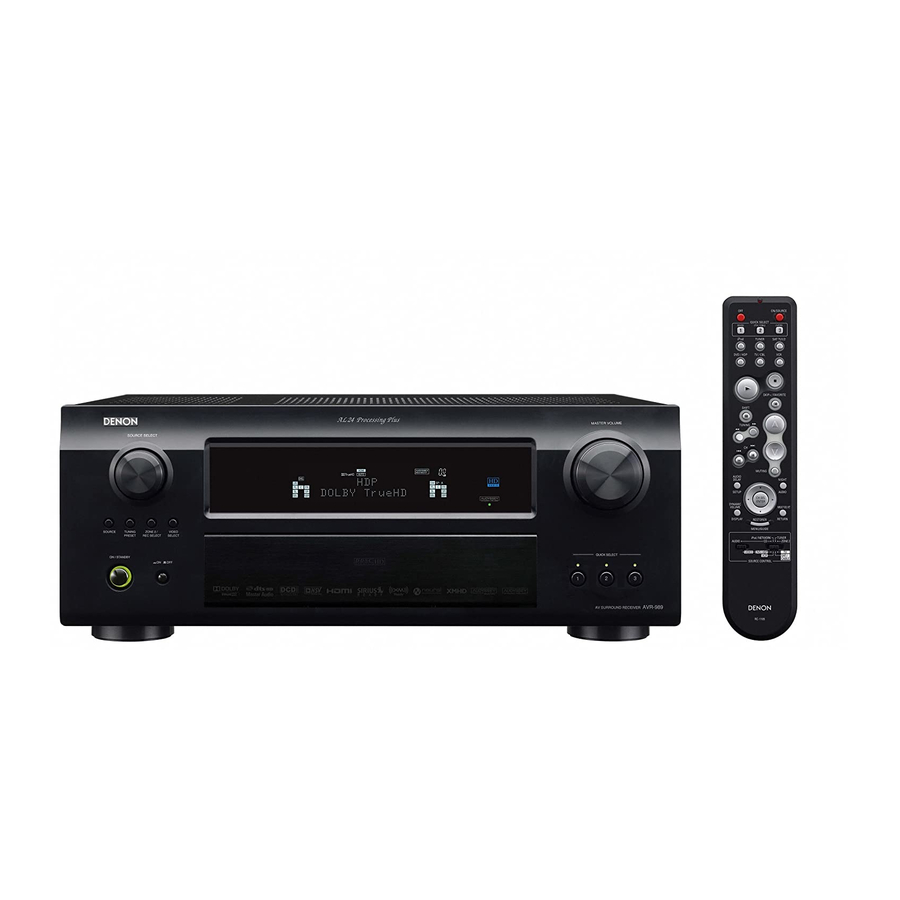
Part Names and Functions For buttons not explained here, see the page indicated in parentheses ( ). Front Panel Q2 Q3 Q4 GWith the door openH Power operation button (ON/STANDBY) ····························· (50) Power indicator ······································································· (50) Power switch (hON jOFF) ·················································· (50) QUICK SELECT buttons / indicators ······································... -
Page 8: Display
Display Input signal indicators Input signal channel indicators These light when digital signals are input. Information display The input source name, surround mode, setting values and other information are displayed here. Output signal channel indicators Front speaker indicator These light according to the settings of the front A and B speakers. -
Page 9: Rear Panel
Rear Panel RS-232C connector · ··································································(19) REMOTE CONTROL jacks ························································(19) TRIGGER OUT jacks ·································································(19) DOCK CONTROL jack ·······························································(13) Speaker terminals (SPEAKERS) ··············································(10) SIGNAL GND terminal ·····························································(13) AC inlet (AC IN) · ······································································· (20) AC OUTLET ·············································································· (20) Digital audio connectors (OPTICAL / COAXIAL)··········· (12 ~ 16) SIRIUS connector (SAT TU1) · ··················································(18) COMPONENT VIDEO connectors ·... -
Page 10: Remote Control Unit
Remote Control Unit [ Front ] Indicator ······················································ (61) Power buttons ············································ (50) QUICK SELECT buttons ····························· (60) Source select buttons ································ (50) b : To select “SIRIUS”, “XM” as the input source, use the System buttons ·········································· (56) AUDIO DELAY button ································ (47) Cursor buttons (uio p) ·························... -
Page 11: Connections
Please select the types of connections suited for the equipment you are connecting. With some types of connections, certain settings must be made on the AVR-989. For details, refer to the instructions for the respective connection items below. NOTE •... -
Page 12: Video Conversion Function
• When only HDMI or component video signals are input to the AVR-989, the characters of the on-screen display are not displayed over the picture. -
Page 13: Speaker Connections
For surround back speakers : • Since “Amp Assign” of AVR-989 is set to “ZONE2” by default, audio is not output from the surround back speakers. When using the surround back speakers with MAIN ZONE, change the “Amp Assign”... -
Page 14: Connecting Equipment With Hdmi Connectors
Bitstream Blu-ray • When the AVR-989 and Blu-ray Disc player / DVD player are connected using an HDMI cable, also connect the AVR-989 and monitor using an HDMI cable. • If the connected monitor or Blu-ray Disc player / DVD player only has a DVI-D connector, use an HDMI/ DVI converter cable. -
Page 15: Connecting The Monitor
Connecting the Monitor • Select the terminal to use and connect the device (vpage 9 “Video Conversion Function”). • With HDMI connections, the video and audio signals can be transferred with a single cable. • To output the audio signals to the monitor with HDMI connections, set menu “Manual Setup” – “HDMI Setup”... -
Page 16: Record Player
• With some record players, noise may be generated when the ground wire is connected. If so, disconnect the ground wire. NOTE The AVR-989’s SIGNAL GND terminal is meant to reduce noise when a record player is connected. This is not a safety ground terminal. CD Player... -
Page 17: Tv/Cable Tuner
TV/CABLE Tuner Select the terminal to use and connect the device. TV tuner When using a coaxial cable for the digital audio connection, make the settings at menu “Input Setup” – “Assign” – “Digital In” (vpage 38). Satellite Receiver Select the terminal to use and connect the device. DBS / BS tuner •... -
Page 18: Connecting The Recording Components
Digital video recorder • Make analog connections if you wish to record analog audio signals. • When recording via the AVR-989, the playback device´s cable must be of the same type as the cable used to connect the AVR-989´s DVR OUT connector. -
Page 19: Cd Recorder / Md Recorder / Tape Deck
• When recording via the AVR-989, the playback device´s cable must be of the same type as the cable used to connect the AVR-989´s VCR OUT connector. Example: CD IN → Analog cable : VCR OUT → Analog cable Connections to Other Devices Carefully check the left (L) and right (R) channels and the inputs and outputs, and be sure to interconnect correctly. -
Page 20: External Power Amplifier
External Power Amplifier Power amplifier When using just one surround back speaker, connect it to the left channel (SBL). Antenna Terminals An F-type FM antenna cable plug can be connected directly. Direction of broadcasting station AM loop antenna (supplied) antenna 75 Ω/ohms Coaxial cable FM indoor... -
Page 21: Xm Connector
XM Satellite Radio Inc. All rights reserved. SIRIUS Connector ® ® • The AVR-989 is a SIRIUS Satellite Radio Ready receiver. You can ® receive SIRIUS Satellite Radio by connecting to the SiriusConnect Home Tuner and subscribing to the SIRIUS service. -
Page 22: Multi-Zone
ZONE2 the same time (vpage 67 ~ 69). • When using an S-Video cable or a video cable for connection between the AVR-989 and an input device, connect to the video connectors. -
Page 23: Connecting The Power Cord
<MENU> ENTER RETURN [Front] [SOURCE CONTROL 1] With the AVR-989, settings and operations for most functions can be performed by operating while looking at the menus displayed on the monitor screen. BUTTON <BUTTON> [BUTTON] Operations The same operation is possible on the main unit or remote control unit. -
Page 24: Example Of Display Of Default Values
Example of Display of Default Values In lists of selectable items or adjustable ranges, the item surrounded by a border is the default value. [Selectable items] B A + B Examples of On-screen Display and Front Display Some typical examples are described below. GFront displayH *MENU Auto Setup... -
Page 25: Menu Map
Menu Map MENU 1.Auto Setup 2.Manual Setup 3.Input Setup 4.Parameter 5.Information Information Parameter (vpage 48, 49) (vpage 42 ~ 47) n Status n Surround Parameter • MAIN ZONE • Mode • ZONE2 • Cinema EQ n Audio Input Signal • DRC n HDMI Information •... -
Page 26: Preparations
Auto Setup Symbols used to indicate buttons in this manual Button located on both the main unit BUTTON and the remote control unit <BUTTON> Button only on the main unit [BUTTON] Button only on the remote control unit ENTER MASTER VOLUME RETURN SETUP MIC jack [Front]... -
Page 27: Auto Setup
For details, refer to “Amp Assign” (vpage 32). NOTE Since “Amp Assign” of AVR-989 is set to “ZONE2” by default, audio is not output from the surround back speakers. When using the surround back speakers with MAIN ZONE, change the “Amp Assign”... - Page 28 Step 2 : Measurement F Menu screen F Auto Setup Audyssey MultEQ XT Auto Setup Step2:Measurement Audyssey MultEQ XT Please place microphone Step2:Measurement at ear height at Now measuring 2nd 2nd listening position. listening position. Next Calculate Front L Cancel Cancel Auto Setup Audyssey MultEQ XT...
-
Page 29: Parameter Check
Please wait... Store Cancel The auto setup measurement results are stored in the AVR-989. q Select “Store 0”, then press • “Storing Please wait ... ” is displayed on the on-screen display while the results are being stored. • When storing is complete, “Storing complete. Auto Setup is now fi nished.”... -
Page 30: Manual Setup
2spkrs 1spkr NOTE Since “Amp Assign” of AVR-989 is set to “ZONE2” by default, audio is not output from the surround back speakers. When using the surround back speakers with MAIN ZONE, change the “Amp Assign” setting to “7.1ch” (vpage 32). -
Page 31: Subwoofer Setup
• Select “Large” or “Small” not according to the physical size of the speaker but according to the low frequency reproduction capabilities based on the frequency set at “Crossover Frequency” (vpage 29). • When “Front Speaker” is set to “Small”, “Subwoofer” can automatically set to “Yes”. -
Page 32: Crossover Frequency
• When the menu “Speaker Configuration” – “Surround Back Speaker” setting (vpage 27) is set to “1spkr”, the surround back speaker display is set to “SB”. • Speakers set to “None” in the “Speaker Configuration” settings are not displayed. • When “Channel Level” is adjusted, the adjusted values are set for all the surround modes. -
Page 33: Hdmi Audio Out
f HDMI Audio Out Select HDMI audio output device. [Selectable items] : Use speakers connected to receiver for audio playback. : Use speakers of TV for audio playback. NOTE When the HDMI control function is operating, the setting of audio playback in the connected TV takes priority (vpage 58 “HDMI Control Function”). -
Page 34: Dolby Digital Setup
d Dolby Digital Setup Set dynamic range for downmix playback of Dolby Digital sources. [Selectable items] : Compression is used. Select this if sound from front speakers is distorted. : Do not use compression. This is the recommended setting. • Set this to “ON” if the sound from the front speakers seems distorted. -
Page 35: Level Rch
s Level Rch Adjust the right channel output level. [Variable range] –12dB ~ ~ +12dB d Volume Level Adjust the main volume level. [Selectable items] : Allow volume adjustment by remote control. –40dB : Fix the volume to –40 dB. : Fix the volume to 0 dB. -
Page 36: Volume Control
For details, see “Amp Assign / Multi-zone Connections and Operations” (vpage 65, 66). s Volume Control Set the MAIN ZONE volume setting. Volume Limit Make a setting for maximum volume. [Selectable items] : Do not set a maximum volume. –20dB : Set the maximum volume to –20 dB. -
Page 37: Quick Select Name
Remote ID Setup Set remote control ID. [Selectable items] When using the AVR-989 with only the included remote control unit (RC-1105), use Remote ID “1” (default). When using a separately sold remote control unit (RC-7000CI, etc.), this function can be used. Match the ID setting of the remote control unit and the receiver. -
Page 38: Input Setup
Input Setup Symbols used to indicate buttons in this manual Button located on both the main unit BUTTON and the remote control unit <BUTTON> Button only on the main unit [BUTTON] Button only on the remote control unit <SOURCE SELECT> INPUT MODE <VIDEO SELECT>... -
Page 39: Settings Related To Playing Input Sources
Changing the input source within Input Setup 3.Input Setup Press u to align the cursor with the top right 1.Assign of the menu screen, and 2.Video press o p to change 3.Input Mode 4.Rename the input source. 5.Source Level The input source currently selected in the MAIN ZONE is not changed even when the input source within Input Setup is changed. -
Page 40: Input Mode
Resolution Make settings for resolution of HDMI video output signal. [Input source] DVD HDP TV/CBL V.AUX [Selectable items] Auto : Detect monitor panel resolution and automatically set output resolution. 480p/576p : Output at 480p/576p resolution. 1080i : Output at 1080i resolution. 720p : Output at 720p resolution. -
Page 41: Rename
“Input Mode” to “Digital”. • When the AVR-989 and monitor are connected with an HDMI cable, if the monitor is not compatible with HDMI audio signal playback, only the video signals are output to the monitor. -
Page 42: L Ipod
• With the default settings, the control dock for iPod can be used connected to the VCR (iPod) connector. • Even if “iPod Dock” is set to “Assign”, if AVR-989 and control dock for iPod are not connected, the input is used as the normal input source. -
Page 43: Surround Modes
Surround Modes Symbols used to indicate buttons in this manual Button located on both the main unit BUTTON and the remote control unit <BUTTON> Button only on the main unit [BUTTON] Button only on the remote control unit DSP SIMULATION PURE DIRECT STANDARD DIRECT/STEREO... -
Page 44: Playing Multi-Channel Sources (Dolby Digital, Dts, Etc.)
MULTI CH IN 7 .1 z1 : This is displayed when the input signal is “DTS-ES Matrix 6.1” and the AVR-989’s “AFDM” setting is set to “ON”. z2 : This is displayed when the input signal is “DTS-ES Discrete 6.1”. -
Page 45: Stereo Playback
Stereo Playback Selecting the mode DIRECT/STEREO Select by press [Selectable items] STEREO This is the mode for playing in stereo. The tone can be adjusted. Sound is output from the front left and right speakers and subwoofer. DIRECT/STEREO When is pressed, DIRECT mode can be switched to STEREO mode. -
Page 46: Surround Parameter
Surround Parameter Adjust surround sound parameters. The parameters (items) which can be adjusted differ depending upon the following conditions. • Whether an input signal is present (when playing) or not (when stopped, etc.). • The type of input signal • The type of surround mode For details of which parameters can be adjusted in each surround mode, see “Surround Modes and Parameters”... - Page 47 When using surround back speakers, adopt the following settings. q A dopt “7.1ch” for the “Amp Assign” setting. The default setting for the Amp Assign mode of AVR-989 is • “ZONE2” . w A dopt a setting other than “OFF” for the “SB CH Out” setting of “Surround Parameter”.
-
Page 48: Tone
A5 SB CH Out (for 2-channel sources) Determine whether to use surround back speakers. [Selectable items] : The surround back channel signal is played. : The surround back channel signal is not played. <SURROUND This operation can be performed directly pressing BACK>... - Page 49 S2 Dynamic EQ Audyssey Dynamic EQ solves the problem of deteriorating sound quality as volume is decreased by taking into account human perception and room acoustics. Audyssey Dynamic EQ works in tandem with Audyssey MultEQ XT to provide well-balanced sound for every listener at any volume level.
-
Page 50: Restorer
RESTORER This function restores compressed audio signals to how they were before compression and corrects the sense of volume of the bass and treble to obtain richer playback sound. [Selectable items] Do not use RESTORER. Mode1 (RESTORER 64): Optimized mode for compressed sources with very weak highs. Mode2 (RESTORER 96): Apply suitable bass and treble boost for all compressed sources. -
Page 51: Status
Information Symbols used to indicate buttons in this manual Button located on both the main unit BUTTON and the remote control unit <BUTTON> Button only on the main unit [BUTTON] Button only on the remote control unit <STATUS> <STATUS> When is pressed, the set’s status can be checked on the display. -
Page 52: Hdmi Information
HDMI Information Shows information about HDMI input signals and monitor. F Menu screen F 5.Information 5-3.HDMI Signal Info. 1.Status 2.Audio Input Signal Resolution 3.HDMI Information 480p 4.Auto Surround Mode 5.Quick Select Color Space RGB 4:4:4 Pixel Depth 8bits 5-3.HDMI Monitor Info. Interface HDMI Support Resolution... -
Page 53: Playback
Playback Symbols used to indicate buttons in this manual Button located on both the main unit BUTTON and the remote control unit <BUTTON> Button only on the main unit [BUTTON] Button only on the remote control unit <SOURCE SELECT> <SOURCE> <MASTER VOLUME>... -
Page 54: Playing Video And Audio Equipment
Symbols used to indicate buttons in this manual Button located on both the main unit BUTTON and the remote control unit <BUTTON> Button only on the main unit [BUTTON] Button only on the remote control unit SOURCE SELECT uio p <TUNING PRESET>... -
Page 55: Listening To Preset Stations
Listening to Preset Stations Operation on the Main Unit <TUNING PRESET> <SOURCE SELECT> Press , then turn to select the preset radio station. Operation on the Remote control Unit [SHIFT] Press to select the memory block (A to G). [CHANNEL + –] [NUMBER (1 ~ 8)] Press to select... -
Page 56: Checking The Xm Signal Strength And Radio
Symbols used to indicate buttons in this manual Button located on both the main unit BUTTON and the remote control unit <BUTTON> Button only on the main unit [BUTTON] Button only on the remote control unit <SOURCE SELECT> uiop <TUNING PRESET> <STATUS>... -
Page 57: Searching Categories
Searching Categories Press Channel category to select the category, then use to select the desired channel. • “LOADING” is displayed while channels or data are being received. • Refer to “Troubleshooting” – “XM Satellite Radio” regarding other messages (vpage 79). Listening to SIRIUS Satellite Radio Programs What is SIRIUS Satellite Radio? -
Page 58: Searching Categories
Basic Operation Make the necessary preparations. q S et the iPod in the DENON control dock for iPod. (vSee the control dock for iPod’s operating instructions.) w Assign the control dock for iPod’s input. The input for the control dock for iPod is assigned to VCR by default. -
Page 59: Listening To Music
(When using an ASD-3N or ASD-3W) NOTE • Depending on the type of iPod and the software version, somefunctions may not operate. (vpage 39) • DENON will accept no responsibility whatsoever for any loss of iPod data. (vpage 39) to select... -
Page 60: Other Operations And Functions
Other Operations and Functions Symbols used to indicate buttons in this manual Button located on both the main unit BUTTON and the remote control unit <BUTTON> Button only on the main unit [BUTTON] Button only on the remote control unit <SOURCE SELECT>... -
Page 61: Convenient Functions
When playing the player, the AVR-989 input function switches to the • function of that player. • When you want to listen to TV audio by AVR-989, connect optical digital or analog. If the TV you are using has both connection jacks, use the optical digital connection. -
Page 62: Channel Level
Put the television power on standby and check if the AVR-989 goes into standby. If the AVR-989 does not work please check the following. • Is the menu “Manual Setup” – “HDMI Setup” – “HDMI Control” (vpage 30) set to “ON”? •... -
Page 63: Quick Select Function
Quick Select Function With this function, the currently playing input source, input mode, surround mode, MultEQ XT settings and volume can be stored in the memory. Set the input source, surround mode, MultEQ XT, Dynamic EQ, Dynamic Volume, Front Speaker settings and volume to the conditions you want to store. -
Page 64: Remote Control Unit Operations
Presetting • DENON and other makes of components can be operated by setting the preset memory. • Operation is not possible for some models. - Page 65 Functions of Buttons by Component n Front [OFF] [ON/SOURCE] [1], [2], [SHIFT, 3], [SETUP], [0, SKIP + / FAVORITE], [uiop], [TUNING, 6 7], [AUDIO], [ENTER], [8 9, CH + –] [DISPLAY], [RETURN], [MENU/GUIDE] [SOURCE [SOURCE CONTROL 1] CONTROL 2] Device CD Player iPod Tuner...
- Page 66 – – Switching the Switching Switching – – display the display the display Return – – Return Return b2 DENON HITACHI – – (121) (108) (007) q, w q, e (Monitor) Channels q TV Volume d w TV Volume f...
-
Page 67: Punch Through Function
[Front] [1], [2], [3], [0], [6 7], [8 9] [SOURCE [SOURCE CONTROL 2] CONTROL 1] [Rear] [NUMBER] [MEMORY] [RETURN] Punch Through Function “Punch Through” is a function allowing you to operate 1, 2, 3, 0, 6, 7, 8 and 9 on CD, iPod/NETWORK, TUNER, DVD/ HDP or VCR components when in the SAT/CABLE or TV mode. -
Page 68: Amp Assign / Multi-Zone Connections And Operations
Multi-zone Settings with the Amp Assign Function The amp assign function lets you assign the amplifiers for the different channels built into the AVR-989 to the speaker outputs for the different zones. Select the desired playback environment from among “Setting 1” to “Setting 3”, then set the corresponding “Amp Assign”... -
Page 69: Multi-Zone Settings And Operations With Zone Output
Remote control unit FL-A/FR-A Bi-Amp connection FL-B/FR-B Bi-Amp connection Audio signals Connectors for video output Stereo ZONE2 VIDEO OUT ZONE2 Monitor Monitor Power amplifier ZONE2 AVR-989 video output Input ZONE2 audio output : Multi-zone video cable : Multi-zone audio cable... -
Page 70: Multi-Zone Operations
Symbols used to indicate buttons in this manual Button located on both the main unit BUTTON and the remote control unit <BUTTON> Button only on the main unit [BUTTON] Button only on the remote control unit <SOURCE SELECT> <VOLUME> <ZONE2 ON/OFF> <ZONE2 / REC SELECT>... -
Page 71: Other Information
Other Information About Speaker Installation Surround back speakers Sound positioning directly to the rear can be achieved easily by adding a surround back speaker to a 5.1-channel system. In addition, the acoustic image extending between the sides and the rear is narrowed, thus greatly improving the expression of the surround signals for sounds moving from the sides to the back and from the front to the point directly behind the listening position. -
Page 72: Dolby Surround
G As seen from the side H Surround The AVR-989 is equipped with a digital signal processing circuit that lets you play program sources in the surround mode to achieve the same sense of presence as in a movie theater. - Page 73 Volume™ is a trademark of Audyssey Laboratories. AL24 Processing Plus AL24 Processing for All Channels DENON has further developed its proprietary AL24 Processing, an analog waveform reproduction technology, to support the 192-kHz sampling frequency. AL24 Processing Plus, thoroughly suppresses quantization noise associated with D/A conversion of LPCM signals to reproduce the low-level signals with optimum clarity that will bring out all the delicate nuances of the music.
-
Page 74: Surround Modes And Parameters
Surround Modes and Parameters Channel output Surround mode Surround Surround Front L/R Center Back L/R PURE DIRECT, DIRECT DSD DIRECT DSD MULTI DIRECT MULTI CH DIRECT STEREO EXT. IN MULTI CH IN DOLBY PRO LOGIC gx DOLBY PRO LOGIC g DTS NEO:6 DOLBY DIGITAL DOLBY DIGITAL Plus... - Page 75 Surround mode PRO LOGIC g/gx MUSIC mode only Panorama Dimension C. Width PURE DIRECT, DIRECT DSD DIRECT DSD MULTI DIRECT MULTI CH DIRECT STEREO EXT. IN MULTI CH IN DOLBY PRO LOGIC gx S (OFF) S (3) S (3) DOLBY PRO LOGIC g S (OFF) S (3) S (3)
- Page 76 Differences in Surround Mode Names Depending on the Input Signals Button Note Surround mode ANALOG STANDARD DTS SURROUND DTS-HD MSTR DTS-HD HI RES DTS ES DSCRT6.1 DTS ES MTRX6.1 DTS SURROUND DTS 96/24 DTS (–HD) + PLgx CINEMA DTS (–HD) + PLgx MUSIC DTS (–HD) + NEO:6 DTS NEO:6 CINEMA DTS NEO:6 MUSIC...
- Page 77 Button Linear Note Surround mode ANALOG (multi STANDARD MULTI CH IN MULTI CH IN MULTI IN + PLgx CINEMA MULTI IN + PLgx MUSIC MULTI CH IN 7 .1 (7 .1) DIRECT DIRECT DSD DIRECT DSD MULTI DIRECT MULTI CH DIRECT M DIRECT + PLgx CINEMA M DIRECT + PLgx MUSIC M DIRECT 7 .1...
- Page 78 Relationship Between Video Signals and Monitor Output Video Input signals convert HDMI COMPONENT S-VIDEO VIDEO HDMI VIDEO S-VIDEO S-VIDEO S (1080p) S (480p ~ 720p) COMPONENT S (480i / 576i) COMPONENT S (1080p) VIDEO S (480p ~ 720p) COMPONENT S (480i / 576i) COMPONENT S (1080p) S-VIDEO...
-
Page 79: Troubleshooting
• Connection of the power cord is • Check that the power plugs turn on, or turns faulty. are securely inserted into the off directly after it AVR-989’s AC inlet and the wall was turned on. power outlet. No sound is • Connection with input •... - Page 80 • Blu-ray Disc player / DVD player • Use a DTS-compatible player. is not compatible with DTS sound playback. • The AVR-989’s “Decode Mode” • Set to the “Auto” or “DTS” setting is set to “PCM”. mode. • The “Manual Setup” – “HDMI •...
- Page 81 Cause No picture • The connections between the • Check the connections. appears. AVR-989 and monitor are faulty. • The monitor’s input setting is wrong. • Set properly. • PURE DIRECT mode is set. • The player is connected using the •...
- Page 82 XM Mini-Tuner dock cable is Mini-Tuner dock is not connected connected to the AVR-989. to the AVR-989. ”CHECK • AVR-989’s XM connector and the • Check that the connections are ANTENNA” is XM Mini-Tuner and Home Dock correct. displayed.
-
Page 83: Specifications
Specifications Audio section • Power amplifier Rated output: Front (A, B): 115 W + 115 W (8 Ω/ohms, 20 Hz ~ 20 kHz with 0.08 % T.H.D.) 145 W + 145 W (6 Ω/ohms, 1 kHz with 0.7 % T.H.D.) Center: 115 W (8 Ω/ohms, 20 Hz ~ 20 kHz with 0.08 % T.H.D.) 145 W (6 Ω/ohms, 1 kHz with 0.7 % T.H.D.) - Page 84 Dynatech Sanyo Electrohome Sony 002, 019, 020 Electrophonic Toshiba 001, 021, 022 Zenith Emerson Blu-Ray Disc Player Flsher [111] (Denon 1) Denon (Denon 2) Go Video Goldstar Gradiente Denon 028, 029, 112 Grundig Magnavox Harley Davidson Mitsubishi Harman Kardon Panasonic...
- Page 85 CD Player 011, 012, 013, 018, 021 002, 003, 022 Aiwa 001, 035, 043 Burmster Carvery 003, 035 014, 023 Denon [111]*, 044 Emerson 004, 005, 006, 007 Fisher 003, 008, 009, 010 018, 019 Kenwood 011, 012, 013, 014, 017...
- Page 86 Denon Brand Company, D&M Holdings Inc. Printed in Japan 5411 10114 000D...