Advertisement
Quick Links
Futaba
DIGITAL PROPORTIONAL
RADIO CONTROL
SPECIAL FEATURES:
TRANSMITTER FP-T2GS
• Contemporary styling with smooth operating gimbals for
superior control.
• 500mW output.
• Battery level meter indicates the state of the battery
voltage at a glance.
• Built-in antenna.
RECEIVER FP-R102GF
•BEC (Battery Eliminator Circuitry) system allows sharing
of the running Nicd battery and eliminates the need for a
regulator and diode.
•High performance 2 channel receiver with ASP system
when used with the proper transmitter.
•Crystal socket uses a new type of highly reliable subminia-
ture pins. Reliability is increased and the crystal can be
changed from the outside.
SERVO FP-S128
SMALL, RUGGED. HIGH NEUTRAL SERVO
•Skew type armature motor.
Movement of the trimmer by even one notch is tracked by
a skew type motor which displays a performance near that
of a coreless motor.
•New indirect drive potentiometer improves vibration and
shock resistance and neutral accuracy.
•Futaba low-power custom 1C provides extremely high
torque, narrow dead band, and superior tracking.
•Fiberglass reinforced PBT (polybutylene terephthalate)
injection molded servo case is mechanically strong and
invulnerable to glow fuel.
•Strong polyacetal resin ultra-precision servo gear features
smooth operation, positive neutral, and very little backlash.
•Fiberglass reinforced epoxy resin PC board with thru-the-
hole plating improves servo amp vibration and shock resist-
ance.
•Three pin connector eliminates faulty contact and improves
reliability against vibration and shock.
reverse insertion prevention mechanism.
•Special grommet simplifies mounting of the servo and has
an excellent cushioning effect.
•Six special adjustable splined horns.
•High 48.7 oz.in (3.5kg-cm) maximum output torque allows
use in almost any model.
FP-2GS
D60431
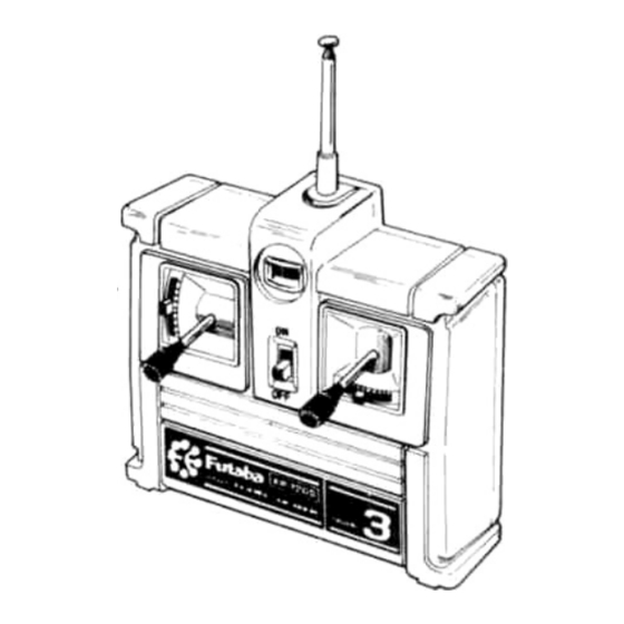
HANDLING THE TRANSMITTER
•The name of each part of the transmitter is given in the figure.
•Remove the battery cover on the rear of the transmitter as
•Extend the antenna fully, and set the power switch to the
Housing has a
•Since the range of the radio waves will become short when
SET CONTENTS AND RATINGS
(Specifications are subject to change without prior notice.)
Model number
Transmitter
Receiver
Servo
Switch, battery holder, etc.
TRANSMITTER FP-T2GS.
Operating method
Transmitting frequency
Modulation system
Power requirement
Receiver FP-R102GF
Receiving frequency
Intermediate frequency
Selectivity
Receiving range
Power supply
Current drain
Dimensions
Weight
SERVO FP-S128
Control system
Operating angle
Power requirement
Current drain (IDLE)
Output torque
Operating speed
Dimensions
Weight
Familiarize yourself with their operation.
illustrated in the figure, and insert 8 round penlight batteries,
paying careful attention to their polarity.
ON position. The pointer of the level meter should deflect to
the green zone. If it fails to deflect, or deflects slowly, the
polarity of the batteries is incorrect, or the batteries are
faulty.
the pointer of the level meter deflects to the red zone, re-
place the batteries when the pointer only deflects to the
boundary between the green and red zones.
FP-2GS
FP-T2GSx1
FP-R102GFx1
FP.S128.x2
2 stick system
27MHz band, 72MHz band
AM (amplitude modulation)
12V, round penlight battery x 8
27MHz band, bands 1 to 6
72,75MHz
455kHz
3kHz/-3dB
550 yards (500m) on the ground
when used with FP-T2GS (At the
best radio wave condition of envi-
ronment)
4.8V to 8.4V
7.2V/13mA,4.8V/33mA
1.46x 2.19 x 0.75 in
(37 x 55.5 x 19mm)
1.34 oz (38g)
+pulse width control
One side 45° or more
4.8V-6V
6.0V, 8mA (at idle)
48.7 oz.in. (3.5 kg-cm)
0.24 sec/60°
1 . 6 x 0 . 8 x 1.6 in.
(40.5 x 20 x 40.5mm)
1.92oz. (53g)
Advertisement

Related Manuals for FUTABA FP-2GS


Summary of Contents for FUTABA FP-2GS
- Page 1 Output torque Operating speed 0.24 sec/60° •Futaba low-power custom 1C provides extremely high 1 . 6 x 0 . 8 x 1.6 in. Dimensions torque, narrow dead band, and superior tracking. (40.5 x 20 x 40.5mm) 1.92oz.
- Page 2 (male pins) (Female pins) The Futaba BEC (Battery Eliminator Circuitry) system and BEC (75MHz-OPTIONAL) & ASP (Adjustable Safety Position) system can also use a com- mon power supply with the conventional four penlight batteries (2) When motor car uses a speci- system (separate power supply).
- Page 3 •The crystal can be changed from the outside of the receiver case. ated and cause the receiver servos to operate erroneously. We re- Always use a Futaba transmitter and receiver crystal pair as the commend the use of noiseless parts.
- Page 4 72MHz band, and vice versa. • Futaba paired crystals are precisely matched. •Therefore, always attach the correct fre- Always use a Futaba crystal set (transmitter, quency flag to the end of the transmitter receiver) when changing the frequency.