
Related Manuals for IBM 4840-563


Summary of Contents for IBM 4840-563
- Page 1 SurePOS 500 Model XX3 Technical System Reference Version: 1.3 SurePOS 500 Model XX3 Technical Reference, v 1.3 Page 1 of 81...
- Page 2 Change History Changes resulting in document revisions will be summarized in this table in reverse chronological sequence. Version Date Change Description 1/28/04 Initial Draft 3/18/04 Revised copy with Engineering inputs, MSR programming interface 3/25/04 Updated System Block diagram, Presence sensor status, and ASIC control registers.
-
Page 3: Table Of Contents
CONTENTS i. Introduction..............................5 iii. Who should read this manual ........................6 iiii. Related publications ..........................7 Chapter 1 Model Specifications ....................8 Factory Select Feature..........................11 Optional Features ............................11 Ship Group ..............................12 Chapter 2 Supported Devices ....................13 Operating System Support.......................... - Page 4 Appendix D Memory Map ......................37 I/O Map ..............................38 PCI Configuration............................40 Interrupt and DMA Assignments ......................... 41 DMA Assignments ............................42 Special SurePOS 500-XX3 POS Devices Interfaces.................. 42 Appendix E ASIC PCI Function 1: POS UARTs ............46 Appendix F Connectors .......................
-
Page 5: Introduction
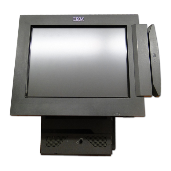
Introduction The IBM 4840 SurePOS 500 Series Point of Sale System is designed to drive the POS transactions within your food service, hospitality, petroleum, and specialty retail providers worldwide. SurePOS 500 – Model 563 (LEADERSHIP, MULTIMEDIA) The sleek leadership model of this family displays excellent visibility in bright light via a 12 inch or 15 inch... -
Page 6: Iii. Who Should Read This Manual
About this manual This manual contains software and hardware information about the IBM SurePOS 500 Series. This manual is organized as follows: • “Chapter 1. General description” on page 1 introduces the various models, the I/O devices that can be attached, and product features. -
Page 7: Iiii. Related Publications
Related publications The following IBM publications are available from the IBM Retail Store Solutions Web site at www.ibm.com/solutions/retail/store/ From there, select Support, then, under Related Links, select Publications. • Safety Information – Read This First, GA27–4004 • SurePOS 500 Series Installation and Operation Guide, GA27–4254 •... -
Page 8: Chapter 1 Model Specifications
Bulb 4840-553 2.0 GHZ Option Yes 12-in 128 Std 256,512,1G, 40 GB HDD 7200 PCCARD/AUDIO Celeron Single Bulb 4840-563 2.0 GHZ Standar Yes 12-in Dual 128 Std 256,512,1G, 40 GB HDD 7200 PCCARD/AUDIO Celeron Bulb 15-in SurePOS 500 Model XX3 Technical Reference, v 1.3... - Page 9 Model Specifications 4840-533 4840-543 4840-553 4840-563 Intel Celeron 2.0 GHz Processor 400 MHz PSB Speed Intel 845GV Chipset Award-based BIOS 128 MB 266 MHz DDR standard Main Memory 2 slots (2 GB max) Intel Extreme Graphics (8MB ) plus DVMT (Max 64MB) (Note 1)
- Page 10 Volume (with speaker kit) DOS 2000, Windows ( 2000, XP, XPe), Linux 130W/200 W max Power Supply – Free Standing (with and without foot) Mounting – Free Standing on cash drawer (std or compact) – Integration Trays: SST/kybd counter, 4610 counter, Std/compact cash drawer –...
-
Page 11: Factory Select Feature
Factory Select Feature Mass Storage 40GB HDD or 512 MB Compact Flash (Model 533) Memory 128MB, 256MB, 512 MB, 1GB, 2 GB 12-in or 15-in (Model 563 only) Dual Video All Models Factory install feature code Optional Features Unless otherwise stated, all features are designated as customer set up and plant/field. Order Feature Comments... -
Page 12: Ship Group
The following items are included with the unit: Cat 5 Ethernet Cable (4.3m), P/N 42L0098 Serial Cable, RJ45 to DB9 (0.7m), P/N 03R7887 The following items are picked packed per order at IBM Distribution Center: Warranty Sheet Installation, Operations, and Planning (optional with specify code) -
Page 13: Chapter 2 Supported Devices
– USB Crystal (if in plan) – 4610-GB3 (Macarena Fiscal USB) Yes - – 4610-TG3/TG4/TG5 USB not – IBM USB Floppy Drive, P/N 05K9276 supported – IBM USB Keyboard, P/N 10K3849 (OBI on DOS P/N) – IBM Memory Key P/N 22P9025 –... -
Page 14: Operating System Support
XP/Xpe Linux (note 2) Notes: 1. DOS Full screen modes not supported 2. IBM Retail Environment for SuSe Linux 3. Windows DBCS versions (Japanese/Korean/Chinese) supported System Software POS Application Interface Drivers POS Application drivers may be more restrictive on operating system support. Refer to the OPOS/JavaPOS specifications for supported operating systems. -
Page 15: Chapter 3 Architectural Overview
Chapter 3 Architectural Overview SurePOS 500 Model XX3 Technical Reference, v 1.3 Page 15 of... -
Page 16: System Block Diagram
System Block Diagram 9/1/03 Touch (Panel or Ring) 24Feb2003 signal backlight button card inverter Tablet Card Tablet Card card Int 2x20 USB x 2 Main card DIMM DIMM Speaker Kit Tailgate Presence Sensor/LED Card USB x 2 Tailgate pwr button pc card headphone microphone... -
Page 17: Main Board Block Diagram
Main Board Block Diagram SurePOS 500 Model XX3 Technical Reference, v 1.3 Page 17 of... - Page 18 XTAL Ethernet PHY 25Mhz 100/133Mhz 4 Phase Vcor Regulator XTAL 32.768Khz ICH4 RTC 100/133Mhz GMCH GTL Bus 66Mhz GMCH HUB Link Celeron/P4 XTAL 24Mhz AC97 Audio 48Mhz GMCH Video Master XTAL Clk Synthesizer 14.318Mhz 66Mhz ICH4 HUB Link Clock 48Mhz ICH4 USB Synthesiz 33Mhz...
-
Page 19: Chapter 4 Physical Characteristics
Chapter 4 Physical Characteristics Dimensions Height (mm) Counter 15" Counter 12" Wallmount 12" Wallmount 15" Tablet at 15 Degrees Tablet Max Front Cable Routing Plate Add 14 ? Add 14 ? Width (mm) Tablet Tablet w/ MSR Base 217 ? 217 ? Depth (mm) Base... -
Page 20: Ports, Controls And Indicators
Ports, Controls and Indicators Port Location and Marking Front Access Area (rotated) Rear Tailgate DISPLAY SurePOS 500 Model XX3 Technical Reference, v 1.3 Page 20 of... -
Page 21: Indicators
Indicators Function Color Location State Power Green Tower Front Off -System Off Blinking - Standby/during POST On - Operational Yellow Tower Front Off - NO activity Blinking - HDD activity Ethernet Green Rear (Ethernet Left LED States connector) – Off - 10 Mb mode –... -
Page 22: I/O Controller Hub, Intel Ich4
1. Without the optional second video adapter, internal LCD and external monitor resolutions and refresh rates will be the same. With the second video adapter feature, internal LCD and external monitor resolutions and refresh rates can be independent of each other.. I/O Controller Hub, Intel ICH4 PCI Bus Controller, Rev 2.2, 33MHz 10/100 Ethernet MAC... - Page 23 The audio subsystems provides the following functions: Audio Codec 97 Revision 2.3 compliant Audio Full duplex capability The audio subsystem consists of the following elements: Realtek Codec AL202A integrated headphone amplifier Headphone and microphone jack External amplified speaker assembly Implementation Notes: Volume control is through normal Windows multimedia controls in combination with a volume control on the speaker unit.
-
Page 24: Network
Network The network subsystem consists of the following elements: Integrated Intel MAC (ICH4) External 10/100 Mbit PHY, 82562ET EEPROM for MAC address The network system provides the following functions: 10/100 Mbps ethernet Support for wake up on LAN using Magic Packet Stores register values, MAC address Extended POS Features The Extended POS I/O subsystem is attached to PCI bus and provides support for additional I/O ports and... -
Page 25: Chapter 6 Power Supply Unit
Chapter 6 Power Supply Unit The main AC power supply is enclosed in a separate metal box but enclosed within the Tower system unit. The heat generated within this supply is separated from the main electronics cavity and is dissipated by an integrated fan assembly. -
Page 26: Touch Panel
Angle (deg) (for CR>=10:1) +10, -30 +40, -60 +/- 45 Vertical Viewing Angle (deg) (for CR>=10:1) 20,000 hrs 50,000 hrs 40,000 hrs Backlight Life (half brightness) 6.9 (max) 11.5 Thickness (mm) Touch Panel Type Infra-red Finger, stylus Input Method (.25-in diameter min.) 1024x1024 Controller... -
Page 27: Disk Drive
DISK DRIVE SurePOS 500 supports industry standard 3.5-inch form factor hard disk drives with AT interface. The maximum thickness supported is 25.4 mm. 40.2 GB Formatted Capacity (GB) IDE (AT) Interface 5400 rpm or 7200 rpm Rotational Speed 512 KB Buffer Size Performance Seek Time (ms) -
Page 28: External Stereo Speaker Unit
External Stereo Speaker Unit SurePOS 500-XX3 supports an external stereo speaker unit. The speaker unit is a self-contained assembly which attaches to SurePOS 500-XX3 using mounting screws. There is a connection provided for input, power and signal, to the speaker unit. The speaker unit contains the drivers and a 1 W per channel amplifier. Design 2 element, 1 way, sealed design Drivers... -
Page 29: 2X20 Displays
5 x 7 5 x 7 Character Box 7.74 x 4.15 9.5 x 4.45 Character Height (mm) Logic Controls Emulation or IBM Multi-Mode Emulations Code Page 437 (US/Euro) Character Sets Code Page 897 (Katakana) (IBM Multi-mode) Code Page 858 (Int'l) -
Page 30: Apa Display
Software Description Boot Control The following boot options are available: LAN RPL - PXE 2.0 and IBM RPL only. External Diskette Drive (standard or USB) USB CD ROM Hard Disk Drive SurePOS 500 Model XX3 Technical Reference, v 1.3... -
Page 31: Setup Configuration Utility
Windows 2000 Windows XP/Xpe IBM Retail Environment for SuSe Linux Maintenance Package The following driver and diagnostic programs are available on the IBM Retail Store Solutions Web site at www.ibm.com/solutions/retail/store/ SurePOS 500 Series Device Drivers SurePOS 500 Series Service Diskette At that site, select Support, then under Software select Download Software Maintenance and select SurePOS 500 Series. -
Page 32: Programming Interface
ROM address space. It is also shadowed into the flash ROM at address F000:FFA0 Vital Product Data (VPD) is the information about an IBM system that can be read with software. The data n includes machine type, machine serial number, BIOS/FLASH ID, system board unique ID, etc. The physical location of the VPD is in the EEPROM attached to the custom SurePOS 500-XX3 ASIC. - Page 33 The spill specification does not apply to the cable attached I/O devices such as the distributed customer display or scanners: IBM RSS Chemical Resistance Test NEMA Type 5 rating per NEMA Standards Publication/No. 250-1997 Enclosures for Electrical Equipment (National Electrical Manufacturers Association) IP 52 rating per IEC 529 (Degrees of Protection by enclosures (IP Code) Internally tested to IP 52 but not declared in safety report.
-
Page 34: Appendix B Power Specifications
Reference Standard Vibration Class V3 C-S 1-9711-002 Shock Class S3 C-S 1-9711-007 Non-Operating Levels Item Reference Standard Packaged (individual, non- IBM C-H 1-9711-005 palletized) Unpackaged Vibration C-H 1-9711-001 Shock (drop table) 50 g's min C-H 1-9711-004 Acoustics Classification Item Category/Class... -
Page 35: Appendix C Standards Compliance
Korea EMI MIC Notice No. 1996-78 Class A New Zealand EMI Class A Australia EMI Class A Radiated Electromagnetic IBM C-S 2-0001-012 Bands 1 through 9 Susceptibility (RES) EN 50024: 1998 (EN61000-4-3) Criteria A Electrical Fast EN 50024: 1998 (EN61000-4-4) Criteria B... - Page 36 Power Frequency Magnetic EN55024:1998 Field Immunity EN61000-4-8 Criteria A IBM C-B 2-0001-028 Power Line Harmonics IBM N-B 2-4700-017, Class A (EN 61000-3-2) (Power Correction Factor) Voltage Flucutations and N-B 2-4700-038 (EN 61000-3-3) Flicker SurePOS 500 Model XX3 Technical Reference, v 1.3...
-
Page 37: Appendix D Memory Map
Appendix D Memory Map ADDRESS ADDRESS SIZE ISA BUS DESCRIPTION RANGE (DEC) RANGE DECODE (HEX) 0 to 639K 00000 to 512K positive, Conventional DOS memory 9FC00 subtractive 639K 9FC00 to positive, EBDA (Extended BIOS Data) 9FFFF subtractive moveable by HIMEM, QEMM, 386MAX 640K to 767K A0000 to... -
Page 38: I/O Map
I/O Map ADDRESS SIZE (DEC) DESCRIPTION REFERENCE (HEX) 0000-001F 32 bytes Intel 82801DB (ICH4), Master DMA Controller Intel 82801DB (ICH4) 0020-003F 32 bytes Intel 82801DB (ICH4), Master Interrupt Intel 82801DB Controller (ICH4) 0030-003F 16 bytes Intel 82801DB (ICH4), Interrupt Controller #1 Intel 82801DB (ICH4) 0040-005F... - Page 39 interface 02F8-02FF 8 bytes SMC LPC47M192, Serial Port 2 (Motherboard) SMC LPC47M192 0377, bit 7 1 bit SMC LPC47M192, Floppy Disk Change SMC LPC47M192 0378-037F 8 bytes SMC LPC47M192, Parallel Port (typical, setup SMC LPC47M192 default) 03F0-03F5 8 bytes SMC LPC47M192, Floppy Controller SMC LPC47M192 03F6 1 byte...
-
Page 40: Pci Configuration
PCI Configuration IDSEL PCI DEVICE PCI Bus PCI IO Register Connection Number Device Address range (hex) Number (hex) Intel 82845GV MCH4 AD(00) Fn 0: Host Bridge 80000000 to internal Fn 2: VGA Graphics 800000FC 80001000 to 800010FC Intel 82801DB (ICH4) Fn 0: USB controller 8000E800 to Fn 1: USB controller... -
Page 41: Interrupt And Dma Assignments
Interrupt and DMA Assignments Most IRQ assignments are dynamic because of Plug-and-Play and PCI configuration. However, some are fixed based on legacy requirements, as shown in the table below. Because the SurePOS 500-XX3 design will make use of the APIC interrupt controller in the ICH4, there will be 20 interrupts instead of 16 as we had in the previous designs. -
Page 42: Dma Assignments
DMA Assignments DATA WIDTH SYSTEM RESOURCE 8 bits only User Available for ISA bus 8 bits only User Available for ISA bus (normally used for LAN) 8 bits only RESERVED, Floppy 8 bits only Parallel Port if ECP, otherwise User Available for ISA bus RESERVED - Cascade Channel 16 bits only User Available for ISA bus... - Page 43 Interrupt Status Register A (Read Only) Offset 41h 3 Status of UART 3 Interrupt Status (0: No Interrupt, 1: Interrupt Asserted) 2 Status of UART 2 Interrupt Status (0: No Interrupt, 1: Interrupt Asserted) 1 Status of UART 1 Interrupt Status (0: No Interrupt, 1: Interrupt Asserted) 0 Status of UART 0 Interrupt Status (0: No Interrupt, 1: Interrupt Asserted) The UARTs are compatible with standard 16550 FIFO UARTs.
- Page 44 1. Determine the PM (Power management) Base IO address. This is done by reading the PCI configuration register 40h-43h of the LPC Interface PCI device. The LPC device is on PCI bus 0, device 1Fh, function 2. 2. Perform logical AND of the lowest word of what is read above with FFFEh. In other words, make the lowest bit = 0 (it always reads a 1 for some reason.) 3.
- Page 45 3 Reserved 0 2 Reserved 0 1 Reserved 0 0 Reserved 0 Distributed VFD Registers (Read Only) Register offset 04h Bit 0 of this register is the logic level of the input pin, E_DIST_VFD_PRESENT#. VFD Registers (Write Only) Register offset 05h Default Value Of VFD Control Register (before EEPROM is loaded): 07h Bit 0: Enable/disable the Distributed VFD TX output, i.e.
-
Page 46: Appendix E Asic Pci Function 1: Pos Uarts
Appendix E ASIC PCI Function 1: POS UARTs In the custom ASIC, SurePOS 500-XX3 provides 4 additional 16550 compatible UARTs, one of which is general use and the other 3 are special-use. The IO address and IRQ are programmable through function 1 of the ASIC. - Page 47 Interrupt Status Register B (Read Only) Offset 41h Bit 3 = Status of UART 3 Interrupt Status (0: No Interrupt, 1: Interrupt Asserted) Bit 2 = Status of UART 2 Interrupt Status (0: No Interrupt, 1: Interrupt Asserted) Bit 1 = Status of UART 1 Interrupt Status (0: No Interrupt, 1: Interrupt Asserted) Bit 0 = Status of UART 0 Interrupt Status (0: No Interrupt, 1: Interrupt Asserted) SurePOS 500 Model XX3 Technical Reference, v 1.3 Page 47 of...
-
Page 48: Appendix F Connectors
Appendix F Connectors Distributed Customer Display Connector Connector CD (carrier detect) RxD (receive data) TxD (transmit data) DTR (data terminal ready) Ground Ground +5 V dc Main +12 V dc +12 V dc +5 V dc Main Dist_VFD present DSR (data set ready) RTS (request to send) CTS (clear to send) - Page 49 RJ45 Serial Port Connector RJ45 to 9 Pin Cable Wiring SurePOS 500 Model XX3 Technical Reference, v 1.3 Page 49 of...
- Page 50 MSR connector Signal Serial Data Out (TTL) Serial Data In (TTL) Ground KBD Enable (low enables kybd data to system) Keyboard data Keyboard clock Ground USB port connector (x 6) Connector 5V VBus -Data +Data Ground SurePOS 500 Model XX3 Technical Reference, v 1.3 Page 50 of...
- Page 51 USB Plus Power 12V/24V Signal Shell Shield VBus Ground Ground Vplus (12V or 24V) Vplus (12 or 24V) Ground Keyboard/Mouse connector Signal Keyboard Data Mouse Data Ground Signal +5 V Main Keyboard Clock Mouse Clock SurePOS 500 Model XX3 Technical Reference, v 1.3 Page 51 of...
- Page 52 Microphone connector Signal Input +5 V Ring Ground Base Headphone Connector Signal Left channel audio Ring Right channel audio Base Ground Parallel Connector Signal Signal STROBE# ATUO FC XT# Data bit 0 Error# Data bit 1 INIT# Data bit 2 SLCT IN# Data bit 3 Ground...
- Page 53 Pin No. Signal name Signal Description Power Ground Power Supply Power Ground Power Ground Drive Select 0. Select drive 0. MTR0 Motor Control 0 Direction. Direction of head movement (0 = inward motion, 1 = outward motion) WDATA Write Data. Encoded data to the drive for write operations.
-
Page 54: Ethernet Connector
diskette is write protected (causes write commands to be ignored) HDSEL Head Select. Selects the side for R/W operations (0 = side 1, 1 = side 0) DSKCHG Disk Change. Sense that the drive door is open or the diskette has been changed Ethernet connector Signal TxD+... - Page 55 Vertical Sync MON ID3 Cash Drawer (x2) Connector Ground Sense Open Internal Customer Display Connector +5V Main Transmit Data Int VFD Present Ground SurePOS 500 Model XX3 Technical Reference, v 1.3 Page 55 of...
-
Page 56: Appendix G Input/Output Device Commands
Sets the specified emulation mode. This example sets Logic Controls emulation mode: 00 00 Character set select (02) <STX> Note: This command is only effective in IBM Mode. 02 nn Purpose: Selects the specified character set. This example selects the US/European character set: 02 00 User character definition (03) <EXT>... - Page 57 * This is maintained for application compatibility with displays with 5x8 character boxes. ←––––5pixelswide ––––→ IBM Mode The byte that follows the command byte represents an address between X'15' and X'1A', or between X'1C' and X'1E' in the currently selected character set. This byte is followed by eight bytes, which define the actual bit patterns of the user-defined character.
- Page 58 Purpose: Increments the cursor position by one. No characters are erased. This command stops the scrolling message if the cursor position is on the top line when the command is sent. At the end of a line, the display behavior is determined by the state of the display control mode as follows:.
- Page 59 Display position (10) <DLE> 10 nn Purpose: Normal display control mode (11) <DC1> Purpose: Sets normal display control mode (DC1) and permits data to be written to either line. After writing a character, the cursor moves one position to the right. When the display position is at the last position of the top line, the cursor moves to the first position of the bottom line.
- Page 60 All byte values between X'00' and X'1F' not defined in this section are ignored by the display in Logic Controls mode. User-defined characters in the IBM mode that have not been defined previously are spaces. APA commands This section describes the following APA VFD commands: v Backspace Without...
-
Page 61: Delete To End Of Line
Purpose: The write-in position is shifted to the most significant digit of the same row. If the write-in position is on the most significant digit, the command is ignored. Clear display 1B 5B 32 4A Purpose: All the displayed characters are erased. The write-in position is not changed. Display position Purpose: Instead of writing the character from the first digit, the write-in start position... - Page 62 2 (X'32') 45 3 (X'33') 58.8 4 (X'34') 70.4 5 (X'35') 100 (default) Cursor mode 1B 5C 3F 4C 43 Ps Purpose: 0 (X'30') 1 (X'31') 2 (X'32') Screen mode This command is only available in 5x7-dot screen mode. The data byte following the command sequence (represented by Ps in the preceding command format), changes the cursor mode.
- Page 63 1B 5C 3F 4C 48 Pm 3B Pl 3B Pt 3B Pn 3B Pd Purpose: This command initiates horizontal scrolling. The control bytes embedded in the command sequence (represented by Pm, Pl, Pt, and Pn in the preceding command format), change the scrolling characteristics. Pd...Pd represents the data bytes.
- Page 64 Purpose: This command specifies the graphic display mode. The control bytes embedded in the command sequence (represented by Px, Py, Ph, and Pw in the preceding command format), change the graphic display characteristics. Pd represents the data byte. Double size letter in horizontal 1B 23 Ps Purpose: This command sets a character with double size letter in horizontal.
- Page 65 Purpose: Selects the language font to use. The command stream is as follows: Pn 30: English -IBM code page 437 modified (default) 31: Japanese -JIS X 0208-1990 32: Korean -KS C 5601-1992 SurePOS 500 Model XX3 Technical Reference, v 1.3...
- Page 66 33: Simplified Chinese -GB-2321 34: Traditional Chinese -BIG5 Cash drawer commands This section describes the following cash drawer commands: v Open Cash Drawer 1 v Open Cash Drawer 2 v Close Cash Drawer 1 v Close Cash Drawer 2 Open cash drawer 1 To open cash drawer 1, use the following command, which sends an ASCII Bell character to the customer display serial port: Open cash drawer 2...
- Page 67 3-Track MSR data Incoming data from the 3-track MSR has the following format: JUCC MSR data Incoming data from the JUCC MSR has the following format: Programming Interface Description Track data switch On the 3 track MSR, the track data interface is chosen with a slide switch located on the MSR such that it is only accessible when the MSR is not attached.
- Page 68 Configuration Word The configuration word is used to alter the format of the track data returned from the MSR. In the default configuration the MSR reads ISO 7811 format cards. There are three possible data tracks. Track one is formatted as 7 bit 1 parity data and is limited to a maximum of 79 characters. Tracks two is formatted as 5 bit 1 parity format with a maximum of 40 characters.
- Page 69 The data from the card is returned as shown in the following Baccus Naur Form: Track data: <Track1><CR><Track2><CR><Track3><CR> Track1: [<Start Sentinel 1><Data1>{1,82}<End Sentinel>]|[<Error>] Track2: [<Start Sentinel 2><Data2>{1,40}<End Sentinel>]|[<Error>] Track3: [<Start Sentinel 3><Data2>{1,107}<End Sentinel>]|[<Error>] 0x0D or Carriage Return Start Sentinel 1: 0x25 or value in configuration byte 2 Start Sentinel 2:...
- Page 70 returns when the data interface is 2-wire serial and defaults to ‘1’ or Carriage returns after tracks when PS/2 is the data interface. Byte 1, Bit 1: Raw Data Mode In this mode control characters within the track data are not removed from the return data. In some MSRs the control characters, “!”#%&’*+,:;<=>?[\]^-“, are removed from the track data before it is sent to the host.
- Page 71 Byte 4: Track 3 start sentinel The value in this byte is used as the track three start sentinels. It is set to 0x2B by default. The value assigned to this byte must be an ASCII code between 49 and 63(‘1’to’?’). This value is substituted in the return data in place of the sentinel found in the track data.
-
Page 72: Reset Switch
Reset switch A pin hole reset switch is provided on the MSR unit in a location not accessible when the MSR is fully installed. When the user presses this switch the MSR configuration word stored in flash is changed back to the factory default and the unit restarts. - Page 73 The following table shows all the commands: Function Comman Format d Byte Reset “00” “:0100001100EE” Set Configuration “01” :0600001101<b1><b2><b3><b4><b5><ss> ss = - (18h +b1+b2+b3+b4+b5) Get Configuration “02” :0200001102<source><ss> : source = “00” from RAM or “01” from flash. From ram: “:020000110200EB” From flash: “020000110201EA”...
- Page 74 Function Success Response Fail Response (return status) Get Configuration “.:nn0000117F<b1><b2><b3><b4><b5 “X” (return status) ><revision string[11]><ss>” Start Update Mode “.” “X” Commit “.” “X” Configuration Custom “.” “X” Configuration Enable/Disable Start Command “.” “X” Mode Start Functional “.” “X” Mode All changes to the configuration word are stored in RAM until a Commit Configuration command is sent. A commit configuration command stores the configuration word into flash where it is retrieved the next time power is restored.
- Page 75 a P889C51RB2 part were used. In this case the code would enable the shadow boot block by setting the ENBOOT bit to ‘1’ and then jumping into ROM at location FC00h. If the watchdog timer is used it should be disabled before jumping to the ISP code.
- Page 76 The ability to read Bank of America mini cards and other non-ISO standard cards is desired. Since some of these cards have higher track density consideration should be given to accommodating them. This effort should not endanger the MSR’s ability to read ISO compliant cards. SurePOS 500 Model XX3 Technical Reference, v 1.3 Page 76 of...
-
Page 77: Appendix H Notices
IBM representative for information on the products and services currently available in your area. Any reference to an IBM product, program, or service is not intended to state or imply that only that IBM product, program, or service may be used. Any functionally equivalent product, program, or service that does not infringe any IBM intellectual property right may be used instead. -
Page 78: Industry Canada Class A Emission Compliance Statement
Properly shielded and grounded cables and connectors must be used in order to meet FCC emission limits. IBM is not responsible for any radio or television interference caused by using other than recommended cables and connectors or by unauthorized changes or modifications to this equipment. Unauthorized changes or modifications could void the user’s authority to operate the equipment. -
Page 79: Australia And New Zealand
In solch einem Fall ist der Abstand bzw. die Abschirmung zu der industriellen Störquelle zu vergröβern.″ Anmerkung: Um die Einhaltung des EMVG sicherzustellen sind die Geräte, wie in den IBM Handbüchern angegeben, zu installieren und zu betreiben. Australia and New Zealand Attention: This is a Class A product. - Page 80 SurePOS 500 Model XX3 Technical Reference, v 1.3 Page 80 of...
- Page 81 END OF DOCUMENT SurePOS 500 Model XX3 Technical Reference, v 1.3 Page 81 of...