Advertisement
5800PIR-OD Wireless Outdoor Motion Sensor – Installation Instructions
GENERAL INFORMATION
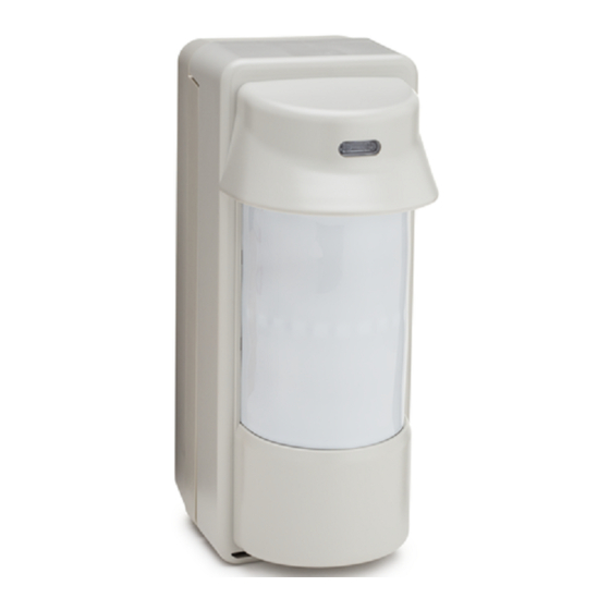
The Honeywell 5800PIR-OD Wireless Outdoor Motion Sensor
(referred to as the 5800PIR-OD) combines the convenience of
wireless technology with a full featured outdoor PIR motion
sensor. The major features are highlighted below:
Immunity to bright light
disturbances from headlights,
sunlight, and other bright
light sources.
Discriminates both large and
small animals to reduce false
alarms.
Tamper detection.
SPECIFICATIONS
Passive Infrared
Detection Method
~ 2 minutes
Initial Warm Up
Height 199mm (7.8 in.)
Dimensions
Width 82mm (3.2 in.)
Depth 120mm (4.7 in.)
0.8 - 1.2m (2.7 - 4ft) To the center of
Mounting Height
lens.
INSTALLATION (refer to the Component Identification Diagram on page 7)
1
Select the Mounting Position
Orient the detector
so that intrusion
passes across the
detection field, not
into the sensor.
2
Prepare the Sensor for Mounting
1.
Remove the Cover by pulling from bottom.
Selectable detector
range and angle.
Battery saving circuit
allows for a 5 or 120
second period of
inactivity before being
reactivated.
Avoid strong sunlight into the sensor's field.
Avoid moving or swaying trees and bushes.
Adjustable up to 12m (40ft)
Range
90° pattern consisting of 13 zones. This
Pattern
pattern can be adjusted in 15° incre-
ments from center up to 45°.
2.0° C at 0.6m/s (3.6° F at 2.0ft/s)
Sensitivity
0.3 - 1.5m/s (1 - 5ft/s)
Detection Speed
6 VDC (uses 4 lithium 1.5VDC AA cells)
Operating Voltage
Adjustable 120sec or 5sec
Battery Saving Timer
~ 2.5 seconds
Alarm Period
Enabled during a walk test.
LED Indicator
Disabled for normal operation.
IP54 compliance
Weatherproof
– 20 to + 50 ° C (– 4 to +122° F)
Operating Temperature
95% Max
Humidity
Pole mounting kit, screw kit, detection
Accessories (included)
masking strips.
Allow 110mm (4.4")
above the sensor to
enable opening the cover.
Choose an installation
height of 0.8m to 1.2m
(2.7 to 4ft).
2.
Remove Detector from the Back Box by pulling from top.
Ensure the sensor can be
mounted on a perpendicular
wall or pole that would make
its detection pattern parallel
to the ground.
Parallel
Advertisement
Table of Contents

Related Manuals for Honeywell 5800PIR-RES


Summary of Contents for Honeywell 5800PIR-RES
-
Page 1: General Information
5800PIR-OD Wireless Outdoor Motion Sensor – Installation Instructions GENERAL INFORMATION The Honeywell 5800PIR-OD Wireless Outdoor Motion Sensor Adjustable up to 12m (40ft) (referred to as the 5800PIR-OD) combines the convenience of Range wireless technology with a full featured outdoor PIR motion 90°... -
Page 2: Wall Mounting
Install / Replace the Battery IMPORTANT: If necessary, loosen the Captive Lock Screw and lift Cover off. Use only lithium batteries. Then, remove 4 screws that secure Use four (4) lithium 1.5VDC AA cells. (Energizer L91 or the Detector to the Back Box. equivalent.) Observe the proper polarity and Change all four batteries at the same time. - Page 3 Perform Settings & Adjustments SET THE DETECTION LENGTH Note: The length of the lower detection area determines the detection length. The upper detection area stays parallel to the ground at all times. The lower detection area can be adjusted by the Detection Length Adjustment Switch as shown below.
-
Page 4: Set The Sensitivity
IF NECESSARY, CONFIGURE DETECTION MASKING Spread the Cover and gently press on the Separate the Lens from the Cover. Then apply the adhesive Masking Lens to remove the Lens Holder. Strip(s), as necessary, inside the lens to mask the desired Cover segments. - Page 5 Perform a Walk Test NOTE: With the Walk Test switch set to ON the LED will light when the detector is tripped, and the alarm is generated instantly. Notes: If this causes a problem, adjust the detection Set the walk test If necessary, adjust length to position "B".
-
Page 6: Troubleshooting
TROUBLESHOOTING SYMPTOM CAUSE REMEDY No detection, when walking Batteries are incorrectly installed or Check for correct battery installation, or replace dead batteries. through the detection area. dead. Wiring is faulty or loose. Check all connectors and wiring. Water in unit. Check for cracks in the housing that would allow water infiltration. - Page 7 COMPONENT IDENTIFICATION DIAGRAM Back Box Use four M4x30 screws if mounting to pole brackets, or two M4x20 screws if mounting to wall. Pole Bracket Sensor (Do not touch) Cover Indicator DIP Switch Sensitivity Select Switch Detection Length Ajustment Switch Captive Lock Screw Transmitter M3 x 10...
-
Page 8: Fcc / Ic Statement
For the latest documentation and online support information, please go to: http://www.security.honeywell.com/hsc/resources/MyWebTech/ WARRANTY For the latest warranty information, please go to: http://www.security.honeywell.com/hsc/resources/wa/ 2 Corporate Center Drive, Suite 100 P.O. Box 9040 Melville, NY 11747 Copyright © 2009 Honeywell International Inc. www.honeywell.com/security ÊK15009V2>Š K15009V2 2/10 Rev. A...