Table of Contents
Advertisement
Quick Links
GF8100 M2+ TE/GF8200C M2+ Setup Manual
FCC Information and Copyright
This equipment has been tested and found to comply with the limits of a Class
B digital device, pursuant to Part 15 of the FCC Rules. These limits are designed
to provide reasonable protection against harmful interference in a residential
installation. This equipment generates, uses, and can radiate radio frequency
energy and, if not installed and used in accordance with the instructions, may
cause harmful interference to radio communications. There is no guarantee
that interference will not occur in a particular installation.
The vendor makes no representations or warranties with respect to the
contents here and specially disclaims any implied warranties of merchantability
or fitness for any purpose. Further the vendor reserves the right to revise this
publication and to make changes to the contents here without obligation to
notify any party beforehand.
Duplication of this publication, in part or in whole, is not allowed without first
obtaining the vendor's approval in writing.
The content of this user's manual is subject to be changed without notice and
we will not be responsible for any mistakes found in this user's manual. All the
brand and product names are trademarks of their respective companies.
Advertisement
Table of Contents

Related Manuals for Biostar GF8200C M2


Summary of Contents for Biostar GF8200C M2
- Page 1 GF8100 M2+ TE/GF8200C M2+ Setup Manual FCC Information and Copyright This equipment has been tested and found to comply with the limits of a Class B digital device, pursuant to Part 15 of the FCC Rules. These limits are designed to provide reasonable protection against harmful interference in a residential installation.
-
Page 2: Table Of Contents
Table of Contents Chapter 1: Introduction ............1 Before You Start ................1 Package Checklist ................1 Motherboard Features..............2 Rear Panel Connectors ..............3 Motherboard Layout................. 4 Chapter 2: Hardware Installation ..........5 Installing Central Processing Unit (CPU)........5 FAN Headers.................. -
Page 3: Chapter 1: Introduction
GF8100 M2+ TE/GF8200C M2+ CHAPTER 1: INTRODUCTION EFORE TART Thank you for choosing our product. Before you start installing the motherboard, please make sure you follow the instructions below: Prepare a dry and stable working environment with sufficient lighting. Always disconnect the computer from power outlet before operation. -
Page 4: Motherboard Features
(Maximum Watt: 95W) Support HyperTransport 3.0 Supports up to 5.2 GT/s Bandwidth GF8100 M2+ TE: GeForce 8100 Chipset GF8200C M2+ : GeForce 8200 Low Pin Count Interface ITE 8718 Environment Control initiatives Super I/O Provides the most commonly used legacy... -
Page 5: Rear Panel Connectors
Special RAID 0 / 1 / 5 / 0+1 support Hybrid SLI support (by nVIDIA driver) Features Biostar reserves the right to add or remove support OS Support Windows XP / VISTA for any OS With or without notice. ANEL... -
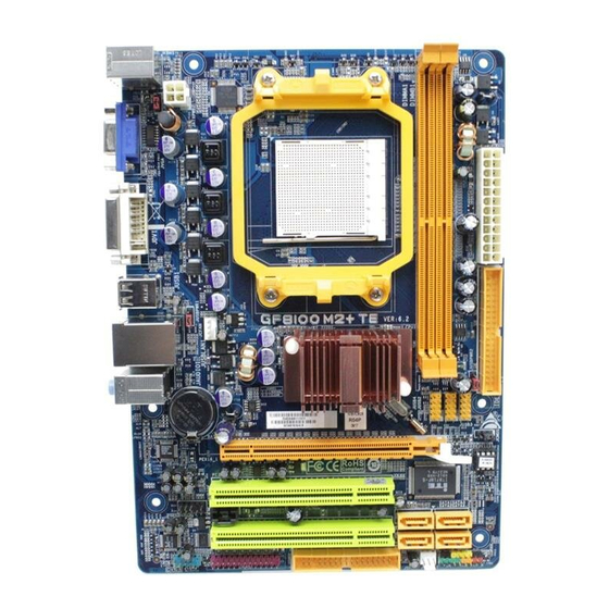
Page 6: Motherboard Layout
Motherboard Manual OTHERBOARD AYOUT JKBMS JATXPWR2 JKB_PWR JATXPWR1 JUSB1 JUS BPWR1 JUSBLAN1 JCFAN GeForce 8100/8200 JAUDIO1 JUSBPWR2 BAT1 JUSB4 JUSB2 JUSB3 JCMOS PEX16_1 BIOS Super I/O PCI1 SATA1 SATA3 JCDIN JAUDIOF PCI2 Codec SATA2 SATA4 JCOM JPRNT JPANEL1 JS FAN Note: represents the 1 pin. -
Page 7: Chapter 2: Hardware Installation
GF8100 M2+ TE/GF8200C M2+ CHAPTER 2: HARDWARE INSTALLATION (CPU) NSTALLING ENTRAL ROCESSING Step 1: Remove the socket protection cap. Step 2: Pull the lever toward direction A from the socket and then raise the lever up to a 90-degree angle. - Page 8 Motherboard Manual Step 4: Hold the CPU down firmly, and then close the lever toward direct B to complete the installation. Step 5: Put the CPU Fan on the CPU and buckle it. Connect the CPU FAN power cable to the JCFAN. This completes the installation. Note: Please update the BIOS to the latest version while using AM2+ CPUs.
-
Page 9: Fan Headers
GF8100 M2+ TE/GF8200C M2+ FAN H EADERS These fan headers support cooling-fans built in the computer. The fan cable and connector may be different according to the fan manufacturer. Connect the fan cable to the connector while matching the black wire to pin#1. -
Page 10: Installing System Memory
Motherboard Manual NSTALLING YSTEM EMORY A. Memory Modules Unlock a DIMM slot by pressing the retaining clips outward. Align a DIMM on the slot such that the notch on the DIMM matches the break on the Slot. Insert the DIMM vertically and firmly into the slot until the retaining chip snap back in place and the DIMM is properly seated. - Page 11 GF8100 M2+ TE/GF8200C M2+ B. Memory Capacity DIMM Socket Total Memory DDR2 Module Location Size DIMMA1 256MB/512MB/1GB/2GB/4GB Max is 8GB. DIMMB1 256MB/512MB/1GB/2GB/4GB C. Dual Channel Memory installation To trigger the Dual Channel function of the motherboard, the memory module must meet the following requirements: Install memory module of the same density in pairs, shown in the following table.
-
Page 12: Connectors And Slots
Motherboard Manual ONNECTORS AND LOTS FDD: Floppy Disk Connector The motherboard provides a standard floppy disk connector that supports 360K, 720K, 1.2M, 1.44M and 2.88M floppy disk types. This connector supports the provided floppy drive ribbon cable. IDE: IDE/ATAPI Connector The motherboard has a 32-bit Enhanced PCI IDE Controller that provides PIO Mode 0~4, Bus Master, and Ultra DMA 33/66/100/133 functionality. - Page 13 GF8100 M2+ TE/GF8200C M2+ PEX16_1: PCI-Express Gen2 x16 Slot PCI-Express 2.0 compliant. Maximum theoretical realized bandwidth of 8GB/s simultaneously per direction, for an aggregate of 16GB/s totally. PCI-Express Gen2 supports a raw bit-rate of 5.0Gb/s on the data pins. 2X bandwidth over the PCI-Express 1.0 architecture.
-
Page 14: Chapter 3: Headers & Jumpers Setup
Motherboard Manual CHAPTER 3: HEADERS & JUMPERS SETUP OW TO ETUP UMPERS The illustration shows how to set up jumpers. When the jumper cap is placed on pins, the jumper is “close”, if not, that means the jumper is “open”. Pin opened Pin closed Pin1-2 closed... - Page 15 GF8100 M2+ TE/GF8200C M2+ JATXPWR1: ATX Power Source Connector This connector allows user to connect 24-pin power connector on the ATX power supply. Assignment Assignment +3.3V +3.3V -12V +3.3V Ground Ground PS_ON Ground Ground Ground Ground Ground PW_OK Standby Voltage+5V...
- Page 16 Motherboard Manual JUSB2~JUSB4: Headers for USB 2.0 Ports at Front Panel These headers allow user to connect additional USB cable on the PC front panel, and also can be connected with internal USB devices, like USB card reader. Assignment +5V (fused) +5V (fused) JUSB2 USB-...
-
Page 17: Cd-Rom Audio-In Connector
GF8100 M2+ TE/GF8200C M2+ JAUDIOF: Front Panel Audio Header This header allows user to connect the front audio output cable with the PC front panel. This header allows only HD audio front panel connector; AC’97 connector is not acceptable. Assignment... -
Page 18: Clear Cmos Procedures
Motherboard Manual JCMOS: Clear CMOS Header By placing the jumper on pin2-3, it allows user to restore the BIOS safe setting and the CMOS data, please carefully follow the procedures to avoid damaging the motherboard. Pin 1-2 Close: Normal Operation (default). Pin 2-3 Close: Clear CMOS data. - Page 19 GF8100 M2+ TE/GF8200C M2+ JPRNT: Printer Port Connector This header allows you to connect printer port on the PC. Assignment Assignment -Strobe Ground -ALF Data 6 Data 0 Ground -Error Data 7 Data 1 Ground -Init -ACK Data 2 Ground...
- Page 20 Motherboard Manual JUSBPWR1/JUSBPWR2: Power Source Headers for USB Ports Pin 1-2 Close: JUSBPWR1: +5V for USB ports at JUSB1/JUSBLAN1. JUSBPWR2: +5V for USB ports at front panel (JUSB2~JUSB4). Pin 2-3 Close: JUSBPWR1: +5V STB for USB ports at JUSB1/JUSBLAN1. JUSBPWR2: +5V STB for USB ports at front panel (JUSB2~JUSB4). JUSBPWR1 Pin 1-2 close JUSBPWR2...
-
Page 21: Chapter 4: Raid Functions
GF8100 M2+ TE/GF8200C M2+ CHAPTER 4: RAID FUNCTIONS PERATING YSTEM Supports Windows XP Home/Professional Edition, and Windows Vista. RRAYS RAID supports the following types of RAID arrays: RAID 0: RAID 0 defines a disk striping scheme that improves disk read and write times for many applications. - Page 22 Motherboard Manual RAID 1: Every read and write is actually carried out in parallel across 2 disk drives in a RAID 1 array system. The mirrored (backup) copy of the data can reside on the same disk or on a second redundant drive in the array. RAID 1 provides a hot-standby copy of data if the active volume or drive is corrupted or becomes unavailable because of a hardware failure.
- Page 23 GF8100 M2+ TE/GF8200C M2+ RAID 0+1: RAID 0 drives can be mirrored using RAID 1 techniques. Resulting in a RAID 0+1 solution for improved performance plus resiliency. Features and Benefits Drives: Minimum 4, and maximum is 6 or 8, depending on the platform.
- Page 24 Motherboard Manual RAID 5: RAID 5 stripes both data and parity information across three or more drives. It writes data and parity blocks across all the drives in the array. Fault tolerance is maintained by ensuring that the parity information for any given block of data is placed on a different drive from those used to store the data itself.
-
Page 25: Chapter 5: Useful Help
GF8100 M2+ TE/GF8200C M2+ CHAPTER 5: USEFUL HELP RIVER NSTALLATION After you installed your operating system, please insert the Fully Setup Driver CD into your optical drive and install the driver for better system performance. You will see the following window after you insert the CD The setup guide will auto detect your motherboard and operating system. -
Page 26: Software
Motherboard Manual OFTWARE Installing Software 1. Insert the Setup CD to the optical drive. The drivers installation program would appear if the Autorun function has been enabled. 2. Select Software Installation, and then click on the respective software title. 3. Follow the on-screen instructions to complete the installation. Launching Software After the installation process, you will see the software icon “eHOT Line”... - Page 27 GF8100 M2+ TE/GF8200C M2+ After filling up this information, click “Send” to send the mail out. A warning dialog would appear asking for your confirmation; click “Send” to confirm or “Do Not Send” to cancel. If you want to save this information to a .txt file, click “Save As…” and then you will see a saving dialog appears asking you to enter file name.
-
Page 28: Bios Update
Motherboard Manual BIOS Update BIOS Update is a convenient utility which allows you to update your motherboard BIOS under Windows system. Show current BIOS information AWARD BIOS AMI BIOS Online Update function Clear CMOS function (Only for AMI BIOS) (Only for AWARD BIOS) Save current BIOS to a .bin file Update BIOS... - Page 29 GF8100 M2+ TE/GF8200C M2+ <Update BIOS> Before doing this, please download the proper BIOS file from the website. For AWARD BIOS, update BIOS procedure should be run with Clear CMOS function, so please check on Clear CMOS first. Then click Update BIOS button, a dialog will show for asking you backup current BIOS.
- Page 30 Motherboard Manual <Online Update> (for AMI BIOS only) Automatically download and update the latest BIOS via internet; make sure that the computer is connected to the internet before using this function. After clicking on the Online Update button, the utility will search for the latest BIOS from internet.
-
Page 31: Extra Information
GF8100 M2+ TE/GF8200C M2+ XTRA NFORMATION CPU Overheated If the system shutdown automatically after power on system for seconds, that means the CPU protection function has been activated. When the CPU is over heated, the motherboard will shutdown automatically to avoid a damage of the CPU, and the system may not power on again. - Page 32 Motherboard Manual BIO-Flasher BIO-Flasher is a BIOS flashing utility providing you an easy and simple way to update your BIOS via USB pen drive or floppy disk. The BIO-Flasher is built in the BIOS chip. To enter the utility, press <F12> during the Power-On Self Tests (POST) procedure while booting up.
-
Page 33: Ami Bios Beep Code
GF8100 M2+ TE/GF8200C M2+ AMI BIOS B Boot Block Beep Codes Number of Beeps Description No media present. (Insert diskette in floppy drive A:) “AMIBOOT.ROM” file not found in root directory of diskette in Insert next diskette if multiple diskettes are used for recovery... -
Page 34: Troubleshooting
Motherboard Manual ROUBLESHOOTING Probable Solution There is no power in the system. Make sure power cable is Power LED does not shine; the securely plugged in. fan of the power supply does not Replace cable. work Contact technical support. Indicator light on keyboard does not shine. - Page 35 GF8100 M2+ TE/GF8200C M2+ This page is intentionally left blank.
-
Page 36: Appendix: Spec In Other Languages
Unterstützt Hyper Transport 3.0 und PowerNow (Maximales Watt: 95W) Unterstützt HyperTransport 3.0 mit einer Bandbreite von bis zu 5.2 GT/s GF8100 M2+ TE: GeForce 8100 Chipsatz GF8200C M2+ : GeForce 8200 Low Pin Count-Schnittstelle ITE8718 Umgebungskontrolle, Bietet die häufig verwendeten alten Super Super E/A Hardware-Überwachung... - Page 37 175 mm (B) X 245 mm (L) Sonderfunkti Unterstützt RAID 0 / 1 / 5 / 0+1 onen Unterstützt Hybrid SLI (by nVIDIA driver) Biostar behält sich das Recht vor , ohne Ankündigung OS-Unterstü Windows XP / VISTA die Unterstützung für ein Betriebssystem tzung...
-
Page 38: French
Prend en charge Hyper Transport 3.0 Bus frontal jusqu'à une bande passante de 5.2 GT/s GF8100 M2+ TE: GeForce 8100 Chipset GF8200C M2+ : GeForce 8200 Interface à faible compte de broches ITE 8718 Initiatives de contrôle environnementales, Super E/S Fournit la fonctionnalité... - Page 39 Prise en charge RAID 0 / 1 / 5 / 0+1 ités Prise en charge Hybrid SLI (by nVIDIA spéciales driver) Biostar se réserve le droit d'ajouter ou de supprimer le Support SE Windows XP / VISTA support de SE avec ou sans préavis.
-
Page 40: Italian
(Watt massimo: 95W) Supporto di HyperTransport 3.0 fino a 5.2 GT/s di larghezza di banda GF8100 M2+ TE: GeForce 8100 Chipset GF8200C M2+ : GeForce 8200 Interfaccia LPC (Low Pin Count) ITE 8718 Funzioni di controllo dell’ambiente: Super I/O Fornisce le funzionalità legacy Super Monitoraggio hardware I/O usate più... - Page 41 Supporto RAID 0 / 1 / 5 / 0+1 iche Supporto Hybrid SLI (by nVIDIA speciali driver) Sistemi Biostar si riserva il diritto di aggiungere o Windows XP / VISTA operativi rimuovere il supporto di qualsiasi sistema supportati operativo senza preavviso.
-
Page 42: Spanish
Admite HyperTransport 3.0 con un ancho de banda de hasta 5.2 GT/s Conjunto GF8100 M2+ TE: GeForce 8100 de chips GF8200C M2+ : GeForce 8200 Interfaz de cuenta Low Pin ITE 8718 Iniciativas de control de entorno, Le ofrece las funcionalidades heredadas Súper E/S... - Page 43 Admite RAID 0 / 1 / 5 / 0+1 especiales Admite Hybrid SLI (by nVIDIA driver) Soporte de Biostar se reserva el derecho de añadir o retirar el Windows XP / VISTA sistema soporte de cualquier SO con o sin aviso previo.
-
Page 44: Portuguese
PowerNow Suporta a tecnologia HyperTransport 3.0 com uma largura de banda até 5.2 GT/s GF8100 M2+ TE: GeForce 8100 Chipset GF8200C M2+ : GeForce 8200 ITE 8718 Interface LPC (Low Pin Count). Especificaç Proporciona as funcionalidades mais Iniciativas para controlo do ambiente ão Super... - Page 45 Suporta as funções RAID 0 / 1 / 5 / 0+1 Suporta as funções Hybrid SLI (by nVIDIA especiais driver) Sistemas A Biostar reserva-se o direito de adicionar ou remover operativos Windows XP / VISTA suporte para qualquer sistema operativo com ou sem suportados...
-
Page 46: Polish
(Maksymalny Watt: 95W) Obsługa HyperTransport 3.0 o szerokości pasma do 5.2 GT/s GF8100 M2+ TE: GeForce 8100 Chipset GF8200C M2+ : GeForce 8200 Gniazda DDR2 DIMM x 2 Moduł pamięci DDR2 z trybem podwójnego kanału Pamięć Maks. wielkość pamięci 8GB Obsługa DDR2 533 / 667 / 800... - Page 47 175 mm (S) X 245 mm (W) płyty Funkcje Obsługa RAID 0 / 1 / 5 / 0+1 specjalne Obsługa Hybrid SLI (by nVIDIA driver) Obsluga Biostar zastrzega sobie prawo dodawania lub systemu Windows XP / VISTA odwoływania obsługi dowolnego systemu operacyjne operacyjnego bez powiadomienia.
-
Page 48: Russian
Поддержка HyperTransport 3.0 с пропускной способностью до 5.2 GT/s Набор GF8100 M2+ TE: GeForce 8100 микросхем GF8200C M2+ : GeForce 8200 Модуль памяти с двухканальным режимом DDR2 Слоты DDR2 DIMM x 2 Поддержка DDR2 533 / 667 / 800 Основная... - Page 49 Поддержка RAID 0 / 1 / 5 / 0+1 ие Поддержка Hybrid SLI (by nVIDIA driver) характери стики Biostar сохраняет за собой право добавлять или Поддержк Windows XP / VISTA удалять средства обеспечения для OS с или без а OS...
-
Page 50: Arabic
ﺗﺪﻋﻢ ﺗﻘﻨﻴﺔHyperTransport ﺑﺘﺮدد یﺼﻞ إﻟﻰ اﻟﺠﺎﻥﺒﻲ اﻷﻡﺎﻡﻲ اﻟﻨﺎﻗﻞ GF8100 M2+ TE: GeForce 8100 اﻟﺸﺮاﺋﺢ ﻡﺠﻤﻮﻋﺔ GF8200C M2+ : GeForce 8200 Low Pin Count Interface ﺗﻘﻨﻴﺔ ﺪﻋﻢ ﺗ ITE 8718 وﺳﺎﺋﻞ اﻟﺘﺤﻜﻢ ﻓﻲ اﻟﺒﻴﺌﺔ Super I/O ﺗﻮﻓﺮ وﻇﻴﻔﺔSuper I/O ً اﻷآﺜﺮ اﺳﺘﺨﺪاﻡ ﺎ... - Page 51 GF8100 M2+ TE/GF8200C M2+ اﻟﻤﻮاﺻﻔﺎت ﻋﺪد SATA ﻡﻨﻔﺬ یﺪﻋﻢ آﻞ ﻡﻨﻔﺬ واﺡﺪ ﻡﻦ أﺟﻬﺰةSATA ﻋﺪد ﻡﻨﻔﺬ اﻟﻠﻮﺡﺔ اﻷﻡﺎﻡﻴﺔ یﺪﻋﻢ ﺗﺠﻬﻴﺰات اﻟﻠﻮﺡﺔ اﻷﻡﺎﻡﻴﺔ ﻋﺪد ﻡﻨﻔﺬ اﻟﺼﻮت اﻷﻡﺎﻡﻲ ﺑﺎﻟﻠﻮﺡﺔ اﻷﻡﺎﻡﻴﺔ یﺪﻋﻢ وﻇﻴﻔﺔ اﻟﺼﻮت ﻋﺪد CD-IN ﻡﻨﻔﺬ یﺪﻋﻢ وﻇﻴﻔﺔ دﺥﻞ ﺹﻮت اﻟﻘﺮص اﻟﻤﺪﻡﺞ...
-
Page 52: Japanese
X2 / Sempron / PhenomX3 プロセッサ ハイパートランスポート3.0とクールアンドクワイアットを (最高のワット: 95W) サポートします 5.2 GT/sのバンド幅までハイパートランスポ ート3.0をサポートします GF8100 M2+ TE: GeForce 8100 チップセッ GF8200C M2+ : GeForce 8200 ト DDR2 DIMMスロット x 2 デュアル チャンネルモードDDR2メモリモジュール DDR2 533 / 667 / 800 をサポート メインメモ 最大メモリ容量8GB 各DIMMは 256MB/512MB/1GB/2GB/4GB DDR2 1066 をサポート... - Page 53 GF8100 M2+ TE/GF8200C M2+ 仕様 フロントパネルコネクタ フロントパネル機能をサポートします フロントオーディオコネクタ フロントパネルオーディオ機能をサポートします CDインコネクタ CDオーディオイン機能をサポートします CPUファンヘッダ CPUファン電源装置(スマートファン機能を搭載) システムファンヘッダ システムファン電源装置 CMOSクリアヘッダ 各コネクタは2つのフロントパネルUSBポートをサポートし USBコネクタ ます 電源コネクタ(24ピン) 電源コネクタ(4ピン) プリンタポートコネクタ 各コネクタは1つのプリンタポートをサポートします シリアルポートコネクタ PS/2キーボード PS/2マウス VGAポート 背面パネル LANポート USBポート オーディオジャック DVIポート ボードサイ 175 mm (幅) X 245 mm (高さ) ズ...