McIntosh C20 Owner's Manual
Hide thumbs
Also See for C20:
- Instruction manual (24 pages) ,
- Maintenance manual (6 pages) ,
- Service manual (4 pages)

Related Manuals for McIntosh C20


Summary of Contents for McIntosh C20
-
Page 1: Table Of Contents
STEREO PREAMPLIFIER GENERAL DESCRIPTION TECHNICAL DESCRIPTION Mechanical Specifications Electrical Specifications FRONT PANEL FACILITIES INSTALLATION CONNECTING A-C Connections Input Connections Output Connections Ground Connections (Program Sources) OPERATING INSTRUCTIONS Balancing a Stereo System To Adjust for Balance in the Treble TABLE OF CONTENTS Range To Adjust for Amplitude Balance in the Bass Range... -
Page 3: General Description
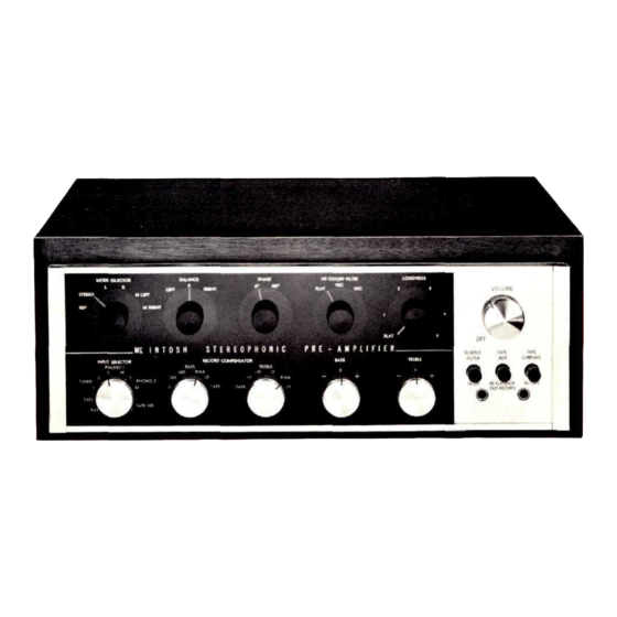
C20 STEREOPHONIC PREAMPLIFIER GENERAL DESCRIPTION The Mclntosh C20 Stereophonic Pre-amplifier is a is affected by variations in environment. Also, people control center for any stereophonic sound system. This listening to the music have varying ideas of correct control center is necessary to accurately perform four tone balance. -
Page 4: Mechanical Specifications
MECHANICAL SPECIFICATIONS WEIGHT DIMENSIONS Chassis: 14-1/2 inches wide; 4-1/2 inches high; 12 Chassis: 18 pounds inches deep Shipping Weight: 28.5 pounds Front Panel: 15-5/8 inches wide; 4-7/8 inches high FINISH Anodized gold and black (front panel) Front Panel Mounting Space Required: 16-3/8 inches wide;... - Page 5 INPUT SELECTOR L . . . left channel to left speaker, no program to right speaker. INPUT SELECTOR R . . . right channel to right speaker, no program PHONO 1 to left speaker. TUNER PHONO 2 M LEFT . . . left channel only to both speakers. M RIGHT .
- Page 6 BALANCE With the RUMBLE FILTER button pushed to the IN position, low-frequency rumble noise below 60 cps BALANCE created by a turntable or changer and undesirable LEFT RIGHT acoustically coupled feedback are reduced. TAPE JACK TAPE JACK This control balances the C20 for unequal pro- gram sources.
-
Page 7: Installation
VOLUME LOW FREQUENCY TRIM VOLUME LOW FREQUENCY TRIM LEFT RIGHT These controls, located on the back panel, com- pensate for unequal speaker response at low frequen- The combined VOLUME control and OFF-on cies due to location of speakers in a room or differ- switch controls the volume for both channels and ences in speaker efficiency. -
Page 8: Connecting
follows: Locate the center of the shelf and scribe a Carefully insert the C20 through the front of the line from front to back. The "SHELF CUTOUT TEM- panel opening so that it rests on the shelf. Insert the PLATE" is marked for panel thicknesses from 1/4" to 1". proper length 6-32 roundhead screws into the four Fold the template on the line that corresponds to the holes in the mounting flanges on each end of the tuner... -
Page 9: Input Connections
Figure 5. C20 Back Panel INPUT CONNECTIONS inputs located on the front panel and controlled by the TAPE JACK pushbutton. The C20 provides eight separate program inputs controlled by the INPUT SELECTOR switch, one input for tape comparison or monitor controlled by the TAPE The input program connection should be made in COMPARE pushbutton, and a pair of telephone jack accordance with Tables 1 and 2. - Page 10 Table 1. High-Level Input Connections INPUT INPUT CONNECTION FUNCTION SENSITIVITY IMPEDANCE TAPE COMPARE The tape compare input accepts a signal 0.25V 115K from a tape recorder with a monitor head and pre-amplifier. The auxiliary input accepts any auxiliary 0.25V 470K service requiring flat frequency response, such as a T.V.
-
Page 11: Output Connections
LEFT AMPLIFIER RIGHT AMPLIFIER Figure 9. MAIN Output Connected to Power Amplifiers The MAIN and TAPE output jacks are fed from cathode followers. The input impedance of devices connected to these outputs should be 50,000 ohms or greater, and the capacitive reactance of audio cables connecting these devices should not be less than 8,000 ohms at 20,000 cycles. -
Page 12: Operating Instructions
OPERATING INSTRUCTIONS rotate RECORD COMPENSATOR control marked BASS BALANCING A STEREO SYSTEM to the TAPE position. The ultimate in stereo performance and listening The music will have an unnatural tone balance dur- enjoyment is obtained through the proper balancing of ing this procedure. -
Page 13: To Adjust The Balance Control After The System Has Been Balanced
3. Set the HF CUTOFF FILTER to FLAT. 5. The microphone frequency response character- istics. 4. Set the LOUDNESS control to FLAT. 6. The recording process influences. 5. Rotate the INPUT SELECTOR to PHONO 1S or PHONO 2S whichever is connected to the cartridge you wish to hear. -
Page 14: Using The C20 Front Panel Tape Jacks
USING THE C20 FRONT PANEL TAPE INPUT JACKS USING THE C20 WITH TAPE DECKS The C20 Stereo Preamplifier may be used with Two tape machines can be used with the C20 Stereophonic Preamplifier. After you have connected tape decks which do not have playback preamplifiers. Tape heads require a form of playback compensation. - Page 15 Table 3. Recommended Settings of the RECORD COMPENSATOR Controls of the C20 for Monophonic Records (Cont) RECORD COMPENSATOR RECORD COMPENSATOR Speed Manufacturer Manufacturer Speed BASS TREBLE BASS TREBLE (Turnover) (Roll-Off) (Turnover) (Roll-Off) London Bartok Boston Lyricord Mercury Blue Note Caedmon Capital RIAA RIAA...
-
Page 16: Operating Curves
OPERATING CURVES = TAPE = RIAA = LP = 300/-5 = 400/-I0 = 0/TAPE A TOTAL OF 25 EQUALIZATION COMBINATIONS ARE POSSIBLE, THE ABOVE SHOWS SEVERAL MOST USED CURVES. 10 KC 20 KC 1 KC FREQUENCY Figure 10. RECORD COMPENSATOR Controls BASS, MAX. - Page 17 10 KC 20 KC 1 KC FREQUENCY Figure 12. RUMBLE FILTER and HF CUTOFF FILTER 10 KC 20 KC 1 KC FREQUENCY Figure 13. LOUDNESS Control Figure 14. BASE TRIM Controls—separate controls are provided for R and L outputs.
-
Page 18: Guarantee
Your C20 will give you many years of pleasant and satisfactory performance. If you have any questions concerning the operation or maintenance of this pre-amplifier please contact: Customer Service Mclntosh Laboratory Inc. 2 Chambers Street Binghamton, New York Our telephone number is 723-5491. The direct dial area code is 607. - Page 20 LABORATORY INC. 2 CHAMBERS STREET, BINGHAMTON, N. Y. Made in U.S.A. Phone —Area Code 607-723-5491 2M-AA117-185 BE102002 Printed in U.S.A.