Dell POWERCONNECT 5524 Getting Started Manual
Powerconnect 5500 series
Hide thumbs
Also See for POWERCONNECT 5524:
- User manual (728 pages) ,
- System user's manual (738 pages) ,
- Release notes (15 pages)

Related Manuals for Dell POWERCONNECT 5524


Summary of Contents for Dell POWERCONNECT 5524
- Page 1 Dell PowerConnect 5500 Series Getting Started Guide Regulatory Models: PowerConnect 5524, 5524P, 5548, 5548P...
- Page 2 Trademarks used in this text: Dell, the DELL logo, Inspiron, Dell Precision, Dimension, OptiPlex, Latitude, PowerEdge, PowerVault, PowerApp, Dell OpenManage and the YOURS IS HERE logo are trademarks of Dell Inc.; Intel, Pentium, and Celeron are registered trademarks of Intel Corporation in the U.S.
-
Page 3: Table Of Contents
Contents Installation Overview Site Preparation Unpacking Package Contents Unpacking the Switch Installing the Switch Installing in a Rack Installing on a Flat Surface Connecting the Switch to Power Supplies Stacking Overview Stacking Switches Unit ID Assignment Automatic Assignment Manual Assignment . - Page 4 Configuring the Switch Configuration Work Flow Connecting the Switch to the Terminal Booting the Switch Configuring the Stack Configuration Using the Setup Wizard Contents ......
-
Page 5: Installation
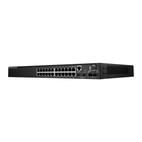
For a complete description of the PowerConnect 5500 series switch, see the Dell PowerConnect 5500 Series User Guide, available on your Documentation NOTE: Even though the graphics in this guide show the Dell PowerConnect 5524P device, the instructions are the same for all models. Site Preparation PowerConnect 5500 series switches can be mounted in a standard 48.26-cm... -
Page 6: Unpacking
• Cabling — The cabling is routed to avoid sources of electrical noise, such as radio transmitters, broadcast amplifiers, power lines, and fluorescent lighting fixtures. • Ambient Requirements — The ambient unit operating temperature range is 0 to 45ºC (32 to 113ºF) at a relative humidity of 10% to 90%, non- condensing. -
Page 7: Installing The Switch
Installing the Switch The PowerConnect 5500 Series switches can be: • Installed on a rack • Placed on a flat surface Installing in a Rack CAUTION: Disconnect all cables from the unit before mounting the switch in a rack or cabinet. CAUTION: When mounting multiple switches into a rack, mount the switches from the bottom up. -
Page 8: Installing On A Flat Surface
3 Repeat the process for the rack-mounting bracket on the other side of the switch. 4 Insert the unit into the 48.26-cm (19-inch) rack, ensuring that the rack-mounting holes on the switch line up to the mounting holes on the rack. -
Page 9: Stacking
Stacking Overview Each switch is a member in a stack, although the stack may consist of only a single switch. Up to eight switches are supported per stack. All stacks must have a Master unit, and may have a Master Backup unit. All other switches are connected to the stack as members (slaves). - Page 10 Figure 2-1 shows this process. Figure 2-1. Stacking Cable Diagram Stacking HDMI Ports HDMI Ports HDMI Ports HDMI Ports...
-
Page 11: Unit Id Assignment
Unit ID Assignment Each switch in the stack has a unique unit ID that defines the unit’s position and function in the stack. Figure 2-2 describes the stacking LEDs on the front panel of the switch. Figure 2-2. Stacking LEDs on Front Panel Unit ID Master The Unit ID of each switch can be either automatically assigned or manually assigned, as described below. -
Page 12: Manual Assignment
ID will be assigned automatically. NOTE: The entire stack should be installed, as shown in Figure 2-1, before powering up the switches. For more information on stacking, see the Dell PowerConnect 5500 Series User Guide on the Documentation CD. Stacking... -
Page 13: Configuring The Switch
Setup Wizard". 4 Respond to the Setup Wizard prompts. 5 Continue managing the switch, either through the console or Telnet, using the CLI or the web GUI, as described in the Dell PowerConnect 5500 Series User Guide. Getting Started Guide... -
Page 14: Connecting The Switch To The Terminal
Connecting the Switch to the Terminal The switch is configured and monitored through a terminal desktop system that runs terminal emulation software. The switch connects to the terminal through the console port. To connect the switch to a terminal: 1 Connect an RS-232 cable to a VT100-compatible terminal or the serial connector of a desktop system running terminal emulation software. -
Page 15: Booting The Switch
Booting the Switch After the local terminal is connected, turn on power. The switch then goes through power-on self-test (POST). POST runs every time the switch is started and checks hardware components, to determine if the switch is operational before completely booting. If the system detects a critical problem, the boot process stops. -
Page 16: Configuring The Stack
Configuring the Stack The switch is always considered to be a stack of switches even if the stack only contains a single switch. If there is more than one switch in the stack, each switch must be configured individually. See "Unit ID Assignment" for instructions on how to configure the stack. - Page 17 2 Boot the Master unit. The system automatically prompts you to use the Setup Wizard. The Setup Wizard displays the following information: Welcome to Dell Easy Setup Wizard The Setup Wizard guides you through the initial switch configuration and gets you up and running easily and quickly.
- Page 18 To manage the switch using SNMP (required for Dell Network Manager) you can: • Setup the initial SNMP version 2 account now. • Return later and set up the SNMP version account. For more information on setting up a SNMP version 2 account, see the user documentation.
- Page 19 7 Set up user account privilege level, as follows: The following information is displayed: Now we need to set up your initial privilege (Level 15) user account. This account is used to login to the CLI and Web interface. You may set up other accounts and change privilege levels later.
- Page 20 12 Enter the default gateway. 13 Press Enter. The following is displayed (example): This is the configuration information that has been collected: SNMP Interface = "Dell Network Manager"@192.168.2.10 User Account setup = admin Password = ********** Management IP address = 192.168.2.100 255.255.255.0...