Table of Contents
Advertisement
Quick Links
See also:
Manual
PROPRIETARY NOTICE AND LIABILITY DISCLAIMER
The information disclosed in this document, including all designs and related materials, is
the valuable property of NEC Corporation (NEC) and/or its licensors. NEC and/or its licen-
sors, as appropriate, reserve all patent, copyright and other proprietary rights to this docu-
ment, including all design, manufacturing, reproduction, use, and sales rights thereto, except
to the extent said rights are expressly granted to others.
The NEC product(s) discussed in this document are warranted in accordance with the terms
of the Warranty Statement accompanying each product. However, actual performance of
each such product is dependent upon factors such as system configuration, customer data,
and operator control. Since implementation by customers of each product may vary, the
suitability of specific product configurations and applications must be determined by the
customer and is not warranted by NEC.
To allow for design and specification improvements, the information in this document is
subject to change at any time, without notice. Reproduction of this document or portions
thereof without prior written approval of NEC is prohibited.
FastFacts, and NEC SVGA, are U.S. trademarks of NEC Technologies, Inc.
All other product, brand, or trade names used in this publication are the trademarks or registered
trademarks of their respective trademark owners.
Copyright 1996
NEC Technologies, Inc.
1414 Massachusetts Avenue
Boxborough, MA 01719
All Rights Reserved
First Printing — June 1996
Copyright 1996
NEC Corporation
7-1 Shiba 5-Chome, Minato-Ku
Tokyo 108-01, Japan
All Rights Reserved
Advertisement
Table of Contents

Related Manuals for NEC VERSA 6000 Series


Summary of Contents for NEC VERSA 6000 Series
- Page 1 The information disclosed in this document, including all designs and related materials, is the valuable property of NEC Corporation (NEC) and/or its licensors. NEC and/or its licen- sors, as appropriate, reserve all patent, copyright and other proprietary rights to this docu- ment, including all design, manufacturing, reproduction, use, and sales rights thereto, except to the extent said rights are expressly granted to others.
-
Page 2: Preface
Troubleshooting and Repair, includes troubleshooting procedures. Section 4 Field Service Guidelines, provides disassembly and assembly procedures, and an exploded-view diagram of the NEC Versa 6000 series system with part numbers. Appendix A Connector Locations and Pin Assignments, provides a list of the main board internal connector pin assignments and a list of external pin assignments. -
Page 3: Table Of Contents
Status Bar and Power Indicator ................1-4 Status Icons....................1-4 Keyboard......................1-5 NEC VersaGlide....................1-6 Diskette Drive and the NEC VersaBay II.............. 1-7 Infrared (IR) Front Assembly................1-7 Hardware Overview—Right Side................. 1-9 Hardware Overview—Left Side................... 1-10 PC Card Slots....................... 1-10 Battery Compartment ................... - Page 4 Determining Battery Status................2-5 When to Change the Battery ................2-6 Battery Handling ................... 2-6 Replacing the Battery Pack ................2-6 Battery Precautions ..................2-9 Recharging Battery Precautions ..............2-9 NEC VersaBay II Battery and Adapter Kit ............ 2-10 Extending Battery Life................... 2-10...
- Page 5 Contents Using the DC Car Adapter..................2-10 Operating Controls ...................... 2-11 Status Bar ......................2-13 Status Icons....................2-13 Function Keys (Fn Keys) ..................2-14 Smart Power Switch ..................... 2-14 Dip Switch ......................2-14 Updating the System BIOS................2-15 Power-On Self-Test (POST)..................2-17 POST Errors ......................
- Page 6 Product Information ....................4-24 Ordering Information from FastFacts................4-24 Appendix A Connector Locations and Pin Assignments Appendix B Video Modes List of Figures NEC Versa 6000 Series Notebook..............1-1 LCD Panel..................... 1-2 Power Button Location ................. 1-3 LCD Status Bar ..................... 1-4...
- Page 7 I/O Board Layout ..................1-15 Connecting the AC Adapter................2-1 Powering on the System ................2-2 Power and I/O Connector Locations .............. 2-3 NEC Versa 6000 AC Adapter................ 2-4 Removing the Cover..................2-7 Removing the Battery ..................2-7 Inserting the Battery Pack................2-8 Replacing the Cover ..................
- Page 8 CPU Board Layout..................A-1 List of Tables Model Configurations ..................1-1 Memory Map....................1-17 NEC Versa 6000 Series Chip Types and Technologies........1-18 Interrupt Controllers..................1-21 Automatic Power-Saving Features ..............1-22 Maximum Performance Default Settings ............1-24 Specifications ....................1-25 I/O Connector Descriptions ................
- Page 9 Contents Parallel Printer Pin Assignments..............A-4 Power Connector................... A-4 Hard Disk Drive Connector ................A-5 LCD Display Mode Setting (800x600 TFT Color LCD & Simultaneous CRT Display ................ B-1 CRT Display Mode (CRT Only) ..............B-3 Panning Video Mode (800x600 TFT Color LCD and Simultaneous CRT Display ................
-
Page 10: Abbreviations
xiii Abbreviations ampere disk operating system alternating current DRAM dynamic RAM advanced technology data terminal equipment (IBM PC) error checking and correction Bulletin Board System error detecting system binary-coded decimal Enhanced Graphics Adapter BIOS Customized Utility Expanded Memory BIOS basic input/output system Specification binary digit enhanced parallel port... - Page 11 Abbreviations Interrupt Request register printed circuit board Industry Standard Architecture plastic flat package In Service register parallel input/output input/output pixel picture element integrated peripheral controller PJQFP plastic J-lead quad flat pack inches per second PLCC plastic lead chip carrier interrupt request phase lock loop kilo (1024) peak-to-peak...
- Page 12 Abbreviations tracks per inch UART universal asynchronous receiver/transmitter volt volts, direct current VESA video electronics standards association variable frequency oscillator Video Graphics Array VLSI very large-scale integration VRAM virtual RAM watt microfarad microprocessor microsecond...
-
Page 13: Section 1 Technical Information
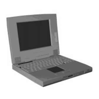
Technical Information The NEC Versa 6000 Series notebook computers are lightweight, compact, and fully IBM compatible. This section focuses on system features. Refer to the NEC Versa 6000 Series User’s Guide for additional user information. The NEC Versa 6000 Series notebook computers are available in the following models:... -
Page 14: Hardware Overview-Front
Figure 1-2 LCD Panel The NEC Versa 6000 series computer features the following LCD types. 11.3-inch SVGA TFT — active matrix Thin Film Transistor (TFT), Cold Cathode Flourescent Tube (CCFT), Super VGA (SVGA) backlit color LCD, 0.29 mm dot pitch, 18-bit digital interface, 800 x 600 resolution and 256,000 colors. -
Page 15: Power Button
Technical Information In addition, the CRT port on the system's rear panel allows the user to connect an optional monochrome or color external display to the system. The computer supports the LCD and external display simultaneously. Power-saving features for controlling the LCD's backlighting include the ROM-based hot key Fn F5, and Auto Setup power management settings. -
Page 16: Status Bar And Power Indicator
Power Management — shows the current power management mode in use, in- cluding Off, Low, High or Custom. Diskette — appears when the NEC Versa writes data to or retrieves data from a diskette. Hard Disk — shows when the NEC Versa writes data to or retrieves data. -
Page 17: Keyboard
Technical Information Battery Status — displays the percentage of battery power available. Battery 1 appears when you have one or more batteries installed. Battery 2 appears when you have an optional battery installed in the VersaBay Keyboard The built-in, 83-key keyboard (U.S) or 79-key keyboard (UK and Germany) uses the stan- dard QWERTY format. -
Page 18: Nec Versaglide
(cursor). To use the VersaGlide, move your finger across the NEC VersaGlide pad, and the cursor follows. The buttons on either side of the NEC Ver- saGlide allow the user to select or deselect menu items. Tap and double-tap are supported on the VersaGlide pad. -
Page 19: Diskette Drive And The Nec Versabay Ii
The front IR assembly consists of a small board with infrared LEDs. The board allows the NEC Versa 6000 series computer to communicate with other infrared-ready computers. For example, the infrared ports allow the user to transfer files between the NEC Versa and an IR-equipped desktop, or print to an IR-equipped printer without using cables. -
Page 20: Front I/R Assembly Location
IR assembly, go into Setup to change the default setting to the front IR assembly. When the NEC Versa 6000 is docked to the optional NEC Versa Docking Station 6000, the rear IR assembly is automatically disabled, and the front enabled. -
Page 21: Hardware Overview-Right Side
Technical Information HARDWARE OVERVIEW—RIGHT SIDE Review the following section for a description of the hardware on the right side of the NEC Versa 6000. Figure 1-10 Right Side Features Modem — NEC includes a 28.8 Kbps fax/voice/data modem with speakerphone and answering machine support. -
Page 22: Hardware Overview-Left Side
Plugging in an external microphone disables the built-in microphone. AC Power Port — Use the power jack to attach the NEC Versa to a DC power source, such as the AC adapter or the optional DC car adapter. -
Page 23: Battery Compartment
If the battery pack is uninstalled for a long period of time, the battery cells are drained, causing battery pack to deteriorate. HARDWARE OVERVIEW—REAR SIDE Review the following section for a description of the hardware on the rear of the NEC Versa 6000. Figure 1-12 Rear Features... -
Page 24: Rear Infrared Port
6000 and NEC Versa Docking Station 6000. Monitor (Video) Port Use this 15-pin port to attach an external monitor to your NEC Versa. You can run the LCD display and the external monitor simultaneously or run either alone. Serial Port (COM 1) The 9-pin serial port provides a serial interface to which you can connect an RS-232C de- vice such as external serial pointing device or modem. -
Page 25: Diskette Drive
Technical Information 1-13 Diskette Drive The interchangeable 3.5-inch 1.44 MB diskette drive installs in the front of the system in the VersaBay II slot. 6x CD-ROM Reader The interchangeable six-speed CD-ROM reader features the latest in CD-ROM technology. It installs in the front of the system in the VersaBay II slot. The CD-ROM reader is assigned to the next available drive letter. -
Page 26: Sound Board
1-14 Technical Information Sound Board The sound board (G8UUT) provides the NEC Versa 6000 series system with its audio ca- pabilities via line-in/line-out jacks, and headphone/microphone jacks. It is situated on top of the I/O board. Figure 1-14 Sound Board Layout... -
Page 27: I/O Board
28,000 bits-per-second, integrating built-in error control. The modem provides one standard phone connector, and one cellular phone connector for transforming the notebook into a speakerphone. NEC provides two analog phone cables (one is a spare) for convenience. The built-in modem is also cellular-capable. To use the computer’s cellular phone connec- tor, the user needs to purchase a cellular phone cable from a computer store. -
Page 28: Cmos Battery
1-16 Technical Information CMOS Battery The lithium battery (3.0 Volts, 280 mAh capacity) is attached to P13 on the CPU board. It provides battery backup and prevents data loss in the system’s complementary metal oxide semiconductor (CMOS) RAM. This memory area contains information on the system’s configuration like date, time, drives, and memory. -
Page 29: Memory Map
Technical Information 1-17 Memory Map The system supports system and video shadowing, both controlled through complementary metal oxide semiconductor (CMOS). The system supports BIOS as a cacheable area with write protection. Table 1-2 lists the system's memory map. Table 1-2 Memory Map Memory Space Size Function... -
Page 30: Serial Interface
Refer to Table 1-3 for a quick summary of the chip types used in the system. See the Ab- breviations section at the beginning of this manual for a translation of chip technologies. Table 1-3 NEC Versa 6000 Series Chip Types and Technologies Chip... -
Page 31: Intel Pentium P54Lm Or P54Cslm
1-19 Intel Pentium P54LM or P54CSLM The 100 MHz, or 133 MHz Intel Pentium microprocessor used in the NEC Versa 6000 se- ries computer is built on Intel’s advanced 3.3V BiCMOS silicon technology. The CPU has on-chip dual-processing, a local multiprocessor interrupt controller, and power management features. -
Page 32: Vga Controller
1-20 Technical Information The ROM BIOS contains both the system and video BIOS. The system BIOS is located in the upper portion of the device, video BIOS is located in the lower portion. System BIOS is located between F000h-FFFFh. The BIOS often changes after the product release to provide enhanced features or bug fixes. -
Page 33: Sound Integrated Circuit
Technical Information 1-21 CardBus slots with hot insertion and removal independent Read and Write buffers for each direction burst transfers to maximize data throughput on the PCI CardBus bus. Sound Integrated Circuit The Creative Vibra™ 16S VLSI chip is a single combo chip. This dynamic audio circuitry provides the following: ISA 16-bit bus interface chip audio digital processor... -
Page 34: Power Management Overview
IRQ07 Parallel Port 1 POWER MANAGEMENT OVERVIEW Power Management in the NEC Versa 6000 lets you conserve energy, save battery power, extend the life of your LCD backlight, and protect against data loss due to low battery power. Set some features to function automatically or activate them manually with the keyboard or a button. -
Page 35: System Power Management
Technical Information 1-23 The NEC PowerPanel Utility icon also allows you to change the timeout period for some of these devices. See Section 2, Setup and Operation for an overview of PowerPanel. Use the key combination to set the power management level. The faucet icon changes Fn F7 when the power management setting changes. -
Page 36: Plug And Play
2 minutes PLUG AND PLAY The NEC Versa 6000 has a Plug and Play functionality. This means you can suspend the system, add an external keyboard, mouse, or monitor, and when you resume working, the NEC Versa 6000 recognizes the devices that have been connected to it. Similarly, you can remove external devices in Suspend mode and the NEC Versa 6000 detects the status when resumed. -
Page 37: Specifications
Technical Information 1-25 SPECIFICATIONS Table 1-7 provides a complete list of NEC Versa 6000 series system specifications. Table 1-7 Specifications Item Specification Chassis Configuration Size Width: 11.69 in. (297 mm) Depth: 9.49 in. (240.5 mm) Height: 11.3-inch model, 2.17 in. (53.5 mm) 12.1-inch model, 2.23 in. - Page 38 External Keyboard/External Mouse — 1 port, PS/2, 6-pin MiniDin; exclusionary use or both supported with optional Y- adapter Expansion — 1 port, for optional NEC Docking Station 6000, optional PortBar 6000 Modem — 2-pin tip/ring connector, 9-pin cellular phone connector Mono MIC IN —...
- Page 39 11.3-inch active matrix Thin Film Transistor (TFT) CCFT Super VGA (SVGA) single-backlit color, 800 x 600 pixels resolution, 0.29 mm dot pitch, 256,000/18 bits colors NEC Versa 6030H 12.1-inch high resolution active matrix Thin Film Transistor (TFT) CCFT Super VGA (SVGA) single-backlit color, 800 x 600 pixels resolution, 0.306 mm dot pitch, 256,000/18 bits...
- Page 40 1-28 Technical Information Table 1-7 Specifications Item Specification Software ® Standard MS-DOS version 6.22 (also provided on diskette) ® Windows for Workgroups version 3.11, or Window 95 WebScan VirusScan Official Airline Guide (OAG®) FaxWorks™ with Voice and Data Communications Netscape Navigator LapLink™...
-
Page 41: Section 2 Setup And Operation
The power switch turns the system on or off. Slide the switch right to turn it on, slide the switch again to turn it off. Connect the AC adapter cable to the power port on right side of your NEC Versa 6000. -
Page 42: Cable Connections
Setup and Operation NOTE: Do not cover or place objects on the AC adapter. This will allow heat to dissipate properly. Ensure that all connections are properly seated and secure. Slide the power button to the right to power on the computer. Figure 2-2 Powering on the System NOTE: If operating the system on DC power, verify that the system has a charged battery pack... -
Page 43: Power Sources
Connects to an RS-232C device. POWER SOURCES The NEC Versa 6000 can be powered using three different sources, as follows: the AC adapter connected to an electrical wall outlet (using AC power) the battery pack or an optional second battery pack the optional DC adapter connected to a car cigarette lighter. -
Page 44: Using The Ac Adapter
Setup and Operation Using the AC Adapter Use the AC adapter and power cable that came with the NEC Versa 6000 to run the com- puter on alternating current (AC) power, or to recharge the battery pack. Use the AC adapter whenever a wall outlet is nearby. -
Page 45: Determining Battery Status
Setup and Operation Leave the battery pack in the system and connect your NEC Versa to the AC adapter and a wall outlet. If you connect the system to AC power and continue to use it, the battery recharges in approximately 2.5 to 7 hours. If you connect the system to AC power and do not use it, the battery recharges in about 2 hours. -
Page 46: When To Change The Battery
Battery Handling Keep the following in mind when removing or replacing a battery. Use Li-Ion batteries only in the NEC Versa computer for which they are designed. Turn off power to the system after use. Keeping system power on can degrade battery performance and shorten battery life. -
Page 47: Removing The Cover
Setup and Operation Figure 2-5 Removing the Cover Place a finger in the notch on the battery and lift the battery out of the system. WARNING: Always lift the battery out of the system by the notch. Failure to do so can damage the battery terminals. -
Page 48: Inserting The Battery Pack
Setup and Operation Insert the new battery as follows: Locate the grooves on the end of the battery. Lower the notched end of the battery into the battery compartment. Figure 2-7 Inserting the Battery Pack Replace the battery bay cover as follows: Align the tabs on the bay cover with the grooves on the system chassis. -
Page 49: Battery Precautions
Recharging Battery Precautions Adhere to the following precautions when recharging the Li-Ion battery. Use only the NEC battery charger designed for your NEC Versa battery type. Different NEC Versa models require different batteries and battery chargers. Change the battery for the specified charge time only. -
Page 50: Nec Versabay Ii Battery And Adapter Kit
(Fn+F5). Or, slide the backlight control to a dimmer level. Using the DC Car Adapter Another way to power the NEC Versa 6000 is via car battery power using the optional DC car adapter. Connect the system to the optional DC car adapter as follows. -
Page 51: Operating Controls
Setup and Operation 2-11 OPERATING CONTROLS The following section describes system controls, the LEDs, and function keys. Refer to Figure 2-10 and Figure 2-11 to locate system controls and switches. Table 2-2 de- scribes the controls. Figure 2-10 Keyboard Panel LEDs and Controls Figure 2-11 Right Side Panel Controls/Ports... -
Page 52: Control And Switch Functions
Allows the user to record monophonic sound directly into the NEC Versa 6000 system. AC Port Use the power jack to attach the NEC Versa to a DC power source, such as the AC adapter or the optional DC car adapter. -
Page 53: Status Bar
Setup and Operation 2-13 Status Bar The NEC Versa 6000 status bar is located in the upper left corner of the keyboard panel. Figure 2-12 shows the status bar. Figure 2-12 Status Bar Location Status Icons The NEC Versa 6000 uses eight icons to let the user determine system status, as follows. -
Page 54: Function Keys (Fn Keys)
Scroll/Lock On/Off Smart Power Switch Provides an automatic feature that prevents you from accidentally powering off the NEC Versa 6000, and losing your data while your system is in Suspend mode. The smart power switch senses that the system is in Suspend mode and prevents you from directly powering off the system when you press the power switch. -
Page 55: Updating The System Bios
Switch 4 — Reserved for factory use. Updating the System BIOS Use the following steps to update the NEC Versa 6000 system BIOS with the BIOS Update diskette (BUD). Specifically, the BIOS is the code transmitted onto your system’s micro- processor, or central processing unit (CPU). -
Page 56: Locating The Switch Settings
Setup and Operation You should only use the BIOS upgrade diskette for the specific model. Check that computer power is off. Turn the NEC Versa 6000 upside down with the front of the unit facing you. Remove the hard disk drive. -
Page 57: Power-On Self-Test (Post)
Setup and Operation 2-17 The utility checks the currently installed BIOS version and the diskette’s BIOS version. The Main Menu appears. Use the arrow keys to highlight the “Display BIOS Version” option on the Main Menu. Use this option to check the currently installed BIOS version and the ver- sion of the new replacement BIOS. -
Page 58: Post Errors
2-18 Setup and Operation NOTE: If the system parameters (date, time, options, etc.) have not been entered for the pres- ent configuration, enter them when you complete the setup procedures (see “System Parameters” in this section). POST Errors Error messages will appear during POST when configuration information does not match the settings stored in memory. -
Page 59: Setup Utility
Setup and Operation 2-19 Table 4-2 POST Error Messages Message Action Keyboard data line failure The keyboard requires repair. Keyboard controller failure The keyboard requires repair. Keyboard stuck key failure A key is jammed. Remove any objects interfering with data entry. If the message remains, the keyboard requires repair. -
Page 60: Setup Screen
2-20 Setup and Operation After you press F2, the system displays the Setup Main screen. The main screen displays the current hardware parameters of your computer. Setup Screen The Setup menu has four areas as shown next. Item-Specific Help Menu Bar Peripherals Security Exit Main... -
Page 61: Setup Keys
Setup and Operation 2-21 Setup Keys Refer to Table 2-5 for a description of Setup Key functions. Table 2-5 Setup Key Functions Function Moves cursor to another field in the menu. For example, pressing Tab moves the cursor up or down a list of current parameters. Up or down arrow Moves the cursor between the displayed parameters. -
Page 62: Parameter Options
2-22 Setup and Operation Press Continue. The system reboots with the saved changes. PARAMETER OPTIONS Refer to Table 2-6 for a complete list of the parameters selectable through Setup. It also lists factory default settings in the mobile mode. Parameter descriptions follow the table. Menu selections for Setup are the same except where noted. - Page 63 Setup and Operation 2-23 Table 2-6 Setup Parameters DEFAULT ALTERNATE PARAMETER SETTING SETTINGS Parallel Mode Unidirectional Unidirectional/Enhanced (EPP) Bi-directional Modem Port COM2** Reconfigurable/ Disabled Docking Station SCSI* Enabled Disabled NumLock Keyboard auto-repeat 30 per sec 2/6/10/13/19/22/27 per rate ½ sec ¼, ¾, 1 sec Keyboard auto-repeat Enabled**...
-
Page 64: Parameter Descriptions
2-24 Setup and Operation Table 2-6 Setup Parameters DEFAULT ALTERNATE PARAMETER SETTING SETTINGS Serial Timeout Standby Timeout 4 min. 1/2/4/6/8/12/15 min/Off Suspend Mode Suspend Save to File/Suspend Only Auto Suspend 10 min. 5/10/15/20/25/30/34 min/Off Timeout Auto Save to File Suspend Warning Tone Standard Full... -
Page 65: Peripherals
Power Management Under AC Normally, whenever AC power is con- nected to the NEC Versa 6000, power management is disabled. If you enable this option, the system uses the power management mode (on or off) you set using the Power Management option. -
Page 66: Security
Press ESC to save the changes and exit Setup. This password can also be used to lock the system at power-on. When you select “Enable on Boot”, each time you start up the NEC Versa, you’ll be prompted for a password. Using the System Password After setting the initial password, a password prompt appears each time the system is pow- ered on only if you select “Enable on Boot”... -
Page 67: Keyboard Lock
If the password is removed, this option is no longer available. POWERPANEL OVERVIEW The NEC Versa 6000 system gives the user a tool that simplifies changing the system con- figuration settings discussed previously in this section, including power management. -
Page 68: Automatic Power-Saving Features
Setup and Operation AUTOMATIC POWER-SAVING FEATURES Table 2-7 lists the NEC Versa 6000 series automatic power conserving features. These features work during battery and AC operation. The features listed below do not work when the optional docking station is connected. -
Page 69: Section 3 Troubleshooting And Repair
Section 3 Troubleshooting and Repair This section focuses on providing you with some information on basic troubleshooting as well as the BIOS, POST Error codes and messages. QUICK TROUBLESHOOTING This section summarizes problems that may develop during system operation and lists sug- gested corrective actions. - Page 70 Troubleshooting and Repair Table 3-1 Quick Troubleshooting Problem Corrective Actions Battery power does not last Make sure that the power management features are enabled. Recharge the battery pack for 1½ hours before using again. Replace the battery pack. System halts during boot sequence Check condition of selected bootload device (diskette or hard disk) for bad boot track or incorrect OS files.
- Page 71 Check if the PCMCIA card is inserted properly and all connections are set. Replace the PCMCIA card. Replace the main boad. NEC VersaGlide doesn’t work Check if PS/2 mouse driver is properly installed. Check VersaGlide cable inside the system if it is inserted properly.
-
Page 72: Helpful Questions
Troubleshooting and Repair HELPFUL QUESTIONS Here are some helpful questions to ask when troubleshooting the notebook: Is there any external power source connected to the computer? Is the battery fully charged? Is the computer turned on and the Power LED activated? Are the LCD display controls set to the minimum level? Is the LCD display switched to the external monitor? Are all cables and devices connected properly and securely? -
Page 73: Beep Codes
Troubleshooting and Repair BEEP CODES Beep codes are used to identify a POST error that occurs when the screen is not available. Once the screen is operating, diagnostic messages are reported to the screen. There are beep codes for both fatal and non-fatal system board errors. NOTE: No beep code is generated if a test is aborted while in progress. -
Page 74: Beep Codes For System Board Errors
Troubleshooting and Repair Beep Codes for System Board Errors The following table provides system beep codes. Table 3-3 BIOS Beep Codes Beep Diagnostic Description Test Performed Code Code none CPU registers test in Pattern test of most of the 16-bit CPU progress or failure registers. - Page 75 Troubleshooting and Repair Table 3-3 BIOS Beep Codes Beep Diagnostic Description Test Performed Code Code 2-1-1 10h-1Fh First 64K RAM chip or The first 64K of RAM is tested with a data line failure on bit x rolling ones test and a pattern test. If any of the rolling ones tests fail, then 2-1-2 the BIOS reports the specific bit that...
- Page 76 Troubleshooting and Repair Table 3-3 BIOS Beep Codes Beep Diagnostic Description Test Performed Code Code 3-1-2 Master DMA register test Pattern test of channels 1 through 3 of in progress or failure. the master DMA controller (starting port address = C4h). Failure results in a system halt.
- Page 77 Troubleshooting and Repair Table 3-3 BIOS Beep Codes Beep Diagnostic Description Test Performed Code Code 3-4-2 Screen retrace test in Over a period of time, the retrace bit progress or failure. (bit0) in the appropriate CRT controller status register (either port 3BAh or 3DAh) is read and tested.
- Page 78 3-10 Troubleshooting and Repair Table 3-3 BIOS Beep Codes Beep Diagnostic Description Test Performed Code Code 4-2-3 Gate A20 failure. To test extended memory, the processor must be placed in protected mode and the A20 line must be enabled. For the memory tests, the BIOS generally uses the keyboard controller to enable A20.
- Page 79 Troubleshooting and Repair 3-11 Table 3-3 BIOS Beep Codes Beep Diagnostic Description Test Performed Code Code 4-4-3 Math coprocessor test in An integer load and store is performed progress or failure. with the math coprocessor. If the values do not match, an error message will be displayed and POST will continue.
-
Page 80: Section 4 Field Service Guidelines
Section 4 Field Service Guidelines This section contains preventive and corrective maintenance procedures for the NEC Versa 6000 Series notebook computers. The first part of the section describes cleaning procedures and preferred handling procedures for sensitive components (for example disk drives, batter- ies). -
Page 81: Cleaning The Notebook's Interior
Field Service Guidelines Cleaning the Notebook’s Interior When servicing the inside of the notebook, remove dust and other foreign particles from in- side the system unit as follows. Remove the top cover and keyboard using the disassembly procedures discussed later in this section. Dust or vacuum (with a rubber-tipped nozzle) the inside of the system unit par- ticularly the motherboard surface. -
Page 82: Handling The Battery Packs
Make sure to leave the computer's cover open for about ten minutes while the heat disperses, before closing the LCD. REQUIRED TOOLS AND EQUIPMENT All NEC Versa 6000 corrective maintenance procedures can be performed using the follow- ing tools: Tweezers... -
Page 83: Disassembly And Reassembly
For complete disassembly of the system unit, follow the disassembly order listed in Table 4-1 to reassemble, follow the table in reverse order. Table 4-1 NEC Versa 6000 Series Disassembly Sequence Sequence Part... -
Page 84: Hard Disk Drive
Field Service Guidelines Hard Disk Drive To disassemble the entire NEC Versa 6000 computer, start by removing the hard disk drive as follows. NOTE: NEC Versa 6000 hard disk drives can be used in other NEC notebook computers such as the NEC Versa 2000 and 4000 Series systems. -
Page 85: Removing The Hard Disk Drive
Field Service Guidelines Remove the hard disk drive as follows: Using your fingers, press down on the hard disk drive at the end closest to the connector. While maintaining pressure, slide the drive towards the front of the system. CAUTION: Do not lift the drive out of the sys- tem before releasing it from the system connec- tor. -
Page 86: Versabay Ii Release Latches
Field Service Guidelines Diskette Drive Remove the diskette drive as follows. Make sure the NEC Versa 6000 is powered off, all options are disconnected, and the LCD panel is closed. Turn the system upside down with the front facing you. -
Page 87: Main Battery Pack (Li-Ion Type)
Figure 4-4 Removing the Standard Diskette Drive Main Battery Pack (Li-Ion Type) Remove the main battery pack as follows. NOTE: Use Li-Ion batteries in the NEC Versa computer for which they are designed. Also, in- stalling another manufacturer’s battery, or using a combination of very old and new batteries can deteriorate battery and equipment performance. -
Page 88: Removing The Battery Compartment Cover
Field Service Guidelines Release the battery cover latch and slide the battery bay cover away from the system. Figure 4-5 Removing the Battery Compartment Cover Place a finger in the notch on the battery and lift the battery out of the system. NOTE: Always lift the battery out of the system by the notch. -
Page 89: Lcd And Top Cover
4-10 Field Service Guidelines LCD and Top Cover Remove the LCD and top cover as follows. Power off the computer. Remove the bottom base unit cover as follows. Turn the computer over with the VersaBay II slot facing towards you. Locate the 10 screws that secure the bottom base unit cover. -
Page 90: Disconnecting The Lcd Connectors
Field Service Guidelines 4-11 Disconnect the two LCD cables from connectors P16 and CN3 on the main board. Figure 4-8 Disconnecting the LCD Connectors Lift the top cover and LCD up and off of the base unit assembly. NOTE: Remove the top cover carefully, so that you don’t damage the plastic. -
Page 91: Power Button, Ir Board, Keyboard
4-12 Field Service Guidelines Power Button, IR Board, Keyboard Remove the power button, IR board and/or keyboard as follows. Remove the LCD and top cover as previously described. The power button is held in place primarily by the computer’s top cover. Once the top cover is removed, just lift the power button out of its retaining inserts. - Page 92 Field Service Guidelines 4-13 Remove the keyboard as follows. Locate the two ribbon cables that attach to the CPU board via connectors P3 and P4. Figure 4-10 Disconnecting Keyboard Cables Use a flat-head screwdriver to push open the connector tabs. Lift the keyboard out of the base unit.
-
Page 93: Lcd Status Bar, Versaglide Assembly, Metal Keyboard Support
4-14 Field Service Guidelines LCD Status Bar, VersaGlide Assembly, Metal Keyboard Support Remove the LCD status bar, VersaGlide and/or metal keyboard support as follows. Remove the LCD and top cover as previously described. Remove the LCD status bar as follows. Locate the ribbon cable that attaches to the CPU board via connector P5. -
Page 94: Bridge Battery, Cmos Battery, Buzzer
Field Service Guidelines 4-15 Bridge Battery, CMOS Battery, Buzzer Remove the bridge battery, CMOS battery, and/or buzzer (speaker) as follows. Remove the following as previously described: top cover keyboard LCD status bar VersaGlide metal keyboard support. To remove the bridge battery disconnect the cable from connector P15 on the I/O board and remove the bridge battery. -
Page 95: Cpu Board, Modem Board
4-16 Field Service Guidelines To remove the buzzer, disconnect the buzzer cable from P13 on the I/O board and remove the buzzer. CPU Board, Modem Board Remove the CPU board and modem board as follows. Remove the following as previously described: top cover keyboard LCD status bar... -
Page 96: Heat Shield, Sound Board, Microphone Assembly
Field Service Guidelines 4-17 The system’s modem board attaches to the back of the CPU board. Now to remove the modem board, turn over the CPU board. Do not touch any of the chips or circuitry on the board. Lift the modem board out of connectors P1 and P2 Heat Shield, Sound Board, Microphone Assembly Remove the heat shield, sound board, and/or the microphone assembly as follows. -
Page 97: I/O Board
4-18 Field Service Guidelines Remove the two screws that secure the heat shield to the base unit and lift up the heat shield. After removing the heat shield, lift the sound board from connectors P1 and P2 on the I/O board. To remove the microphone assembly, locate the cable attached to the assembly. -
Page 98: Illustrated Parts Breakdown
The next section contains the NEC part numbers and illustrated parts breakdown (IPB) fig- ure for the NEC Versa Series 6000. Figure 4-16 shows the system exploded view diagram, or IPB. Table 4-2 lists field-replaceable parts and corresponding part numbers. - Page 99 4-20 Field Service Guidelines Figure 4-16 NEC Versa 6000 Ilustrated Parts Breakdown...
-
Page 100: Nec Versa 6000 Series Field-Replaceable Parts
Field Service Guidelines 4-21 Table 4-2 NEC Versa 6000 Series Field-Replaceable Parts Item Part Number 1. Speaker with Cable (also called Buzzer) 802-870018-007A 2. CMOS Battery 804-021107-004A 3. Bridge Battery 804-021205-002A 4. Battery Compartment Cover (Cap) 136-238578-001A 5. PCMCIA Slot Cover (Cap) 136-238588-001A 6. - Page 101 4-22 Field Service Guidelines Table 4-2 NEC Versa 6000 Series Field-Replaceable Parts Item Part Number 27. Hard Disk Compartment Cover 136-238579-001A 28. 1 GB Hard Disk Drive OP-220-62005 1.35 GB Hard Disk Drive OP-220-62006 1.44 GB Hard Disk Drive OP-220-62007 29.
-
Page 102: Service Information
NEC Technologies Technical Support Center (TSC) provides an E-mail service for Internet users besides the support listed in Table 5-1. Technical questions regarding NEC products can be sent over the Internet system to TSC. The Internet address is as follows: tech-support@nectech.com... -
Page 103: Product Information
TSC will reply to all questions received by Internet of fax within one business day. PRODUCT INFORMATION NEC FastFacts is an automated electronic information service used to obtain up-to-date product application notes, installation procedures, troubleshooting tips, data sheets, techni- cal information bulletins, price lists, and other information. - Page 104 Field Service Guidelines 4-25 The information requested will be sent automatically to your fax machine. If Fast- Facts attempts to send the second order before the first order is completed, the order could be canceled. After three tries, FastFacts assumes that the line is busy and will not process the order.
-
Page 105: Appendix A Connector Locations And Pin Assignments
Appendix A Connector Locations and Pin Assignments Figure A-1 and Table A-1 show CPU board connectors. The remaining tables provide pin assignments for additional system connectors. Figure A-1 CPU Board Layout... -
Page 106: Lcd Status Bar
Connector Locations and Pin Assignments Table A-1 CPU Board Connectors Connector Description P3 and P4 Keyboard Connectors LCD Status Bar VersaGlide Assembly Connector Rear Infrared Assembly Connector P11 and P12 Front Infrared and LED Assembly Table A-2 Keyboard/Mouse Connectors Signal KeyboardData MouseData Ground... -
Page 107: Serial Port Connector Pin Assignments
Connector Locations and Pin Assignments Table A-3 Serial Port Connector Pin Assignments Signal Data Carrier Receive Data Transmit Data Data Terminal Ready Ground Data Set Ready Request to Send Clear to Send Ring Indicator Table A-4 CRT Connector Pin Assignments Signal Green Blue... - Page 108 Connector Locations and Pin Assignments Table A-5 Parallel Printer Pin Assignments Signal - Strobe Data Bit 0 Data Bit 1 Data Bit 2 Data Bit 3 Data Bit 4 Data Bit 5 Data Bit 6 Data Bit 7 - Acknowledge Busy Select - Auto Feed XT...
- Page 109 Connector Locations and Pin Assignments Table A-7 Hard Disk Drive Connector Signal HDD Access LED Chip Select 0 Chip Select 1 Address 0 Address 2 Address 1 Diagnostic Not Used Not Used Not Used IO Channel Ready MS Select IO Write I/O Read Not Used Data 0...
- Page 110 Connector Locations and Pin Assignments Table A-7 Hard Disk Drive Connector Signal Data4 Ground Data4 Ground Data5 Ground Data10 Ground Data6 Ground Data9 Ground Data7 Not Used Ground Ground RESET Ground...
-
Page 111: Appendix B Video Modes
Appendix B Video Modes The following tables list NEC Versa 6000 system video modes. Table B-1 LCD Display Mode Setting (800x600 TFT Color LCD & Simultaneous CRT Display) Mode Display Text Refresh (Hex) Mode Colors Display Resolution Font Rate Text... - Page 112 Video Modes Table B-1 LCD Display Mode Setting (800x600 TFT Color LCD & Simultaneous CRT Display) Mode Display Text Refresh (Hex) Mode Colors Display Resolution Font Rate Text Mono 80x25 720x350 9x14 Text Mono 80x25 720x350 9x14 7*** Text Mono 80x25 720x400 9x16...
- Page 113 Video Modes Table B-2 CRT Display Mode (CRT only) Mode Display Text Refresh (Hex) Mode Colors Display Resolution Font Rate 0, 1 Text 40x25 320x200 0*, 1* Text 40x25 320x200 8x14 0**, 1** Text 40x25 360x400 9x16 2, 3 Text 80x25 640x200 2*, 3*...
- Page 114 Video Modes Table B-3 Panning Video Mode (800x600 TFT Color LCD and Simultaneous CRT Display) Mode Display Text Font Refresh (Hex) Mode Colors Display Resolution Size Rate Graphics(L) 256 100x37 800x600 8x16 (128x48) (1024x768) Graphics(L) 256 100x37 100x37 8x16 (160x64) (160x64) Graphics(L) 32K 100x37...
- Page 115 Index DC car adapter, 2-10 Default power management settings, 1-24 AC adapter, 2-3 Disassembly guidelines, 4-4 AC power port, 1-10 Diskette controller, serial interface, parallel Accessing setup, 2-19 interface, 1-20 Active mode, 1-23 Diskette drive, 1-7, 1-13 Automatic power saving, 2-28 Display, 1-27 Automatic power saving features, 1-22 Expansion port, 1-12...
- Page 116 Modem, 1-9 Quick troubleshooting, 3-1 Monitor port, 1-12 Mouse port, 1-11 Rear IR port, 1-12 NEC Versa 6000 disassembly sequence, 4- Recharging the battery, 2-5 Removing a password, 2-27 Replacing the battery pack, 2-6 ROM BIOS, 1-19 Operating controls, 2-11...
- Page 117 Index-3 Standby mode, 1-23 Status bar, 1-4, 2-13 VersaBay II, 1-7 Status icons, 1-4 VersaGlide, 1-6 Suspend mode, 1-23 VGA controller, 1-20 Switch settings, 2-14 Video mode System disassembly CRT only, 1-17 bridge battery, 4-15 Video RAM, 1-17 buzzer, 4-15 Volume control, 1-9 CMOS battery, 4-15 CPU board, 4-16...
- Page 118 (For United States Use Only) FEDERAL COMMUNICATIONS COMMISSION RADIO FREQUENCY INTERFERENCE STATEMENT WARNING: Changes or modifications to this unit not expressly approved by the party responsible for compliance could void the user’s authority to operate the equipment. NOTE: This equipment has been tested and found to comply with the limits for a Class B digital device, pursuant to Part 15 of the FCC Rules.